
Instruction Manual

FUEL SYSTEM AND GOVERNOR
49
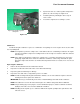
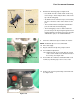
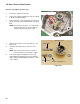
8. Examine the metering plug: See Figure 4.28.
• Fuel, drawn from the central column via the long
fuel feed leg, is metered by the brass orifice in the
tip of the metering plug.
• Air, drawn from the emulsion air port, is metered by
the size of the brass orifice at the entrance to the
port.
• The fuel and air that feed the pilot and transition
ports are mixed at the metering plug.
• The metering plug creates a small venturi. The
pressure drop of the air passing through the meter-
ing plug draws the fuel into the passage to the pilot
and transition ports, in an emulsified mixture.
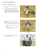
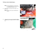
9. Clean the carburetor body in an ultrasonic cleaner.
NOTE: Traditional dips are not recommended.
10. Rinse thoroughly.
11. Dry the carburetor body using compressed air.
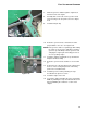
12. Pre-installation adjustment:
12a. Tighten the idle speed screw until 1/8” (3 mm)
of the screw is visible on the throttle arm side of
the housing. See Figure 4.29.
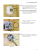
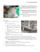
13. Reassemble the carburetor and install it with a new
fuel line, by following steps 1-8 in reverse order.
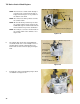
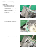
14. Remove the governor guard using a 10 mm wrench.
See Figure 4.30.
Figure 4.28
O-ring seals
Air passage
End view
Fuel metering orifice
Figure 4.29
Idle Speed Screw
Figure 4.30
Governor guard