
User guide

T2
®
17
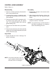
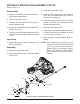
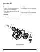
Refer to Figure 8
PULLEY AND FAN CONFIGURATION
1. Remove the locknut (152), and detach the
fan and pulley assembly from the input
shaft.
2. Separate the assembly by removing the
screws (153), fan (150) and the pulley
(151).
I
nspection
1. Check all components for wear or damage.
Replace if necessary.
Assembly
1. Reassemble all parts in the reverse order
of disassembly.
2. When tightening the fasteners, refer to the
table on page 15 for the required torque
values.
NOTE: As a general rule, use the low end of
the torque specication on fasteners
when reassembling the unit.
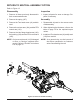
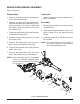
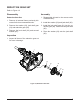
Refer to Figure 9
FAN AND PULLEY CONFIGURATION
1. Remove the locknut (152) and washer
(153).
2. Remove the fan (150) and the pulley
(151).
Inspection
1. Check all components for wear or damage.
Replace if necessary.
Assembly
1. Reassemble all parts in the reverse order
of disassembly.
2. When tightening the fasteners, refer to the
table on page 15 for the required torque
values.
Figure 8, Fan on bottom conguration Figure 9, Fan on top conguration
FAN AND PULLEY
152
153
150
151
152
151
150
153