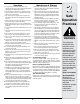
Safety • Assembly • Operation • Adjustments • Maintenance • Troubleshooting • Parts Lists • Warranty OPERATOR’S MANUAL Two-Stage Snow Thrower — Model SWE 528 IMPORTANT READ SAFETY RULES AND INSTRUCTIONS CAREFULLY BEFORE OPERATION Warning: This unit is equipped with an internal combustion engine and should not be used on or near any unimproved forest-covered, brushcovered or grass-covered land unless the engine’s exhaust system is equipped with a spark arrester meeting applicable local or state laws (if an
This Operator’s Manual is an important part of your new snow thrower. It will help you assemble, prepare and maintain the unit for best performance. Please read and understand what it says. Table of Contents Customer Support............................................... 2 Safety Labels....................................................... 3 Safe Operation Practices.................................... 4 Setting Up Your Snow Thrower........................... 6 Operating Your Snow Thrower..................
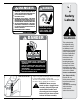
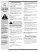
$!.'%2 +%%0 !7!9 &2/- 2/4!4).' )-0%,,%2 !.$ !5'%2 #/.4!#4 7)4( )-0%,,%2 /2 !5'%2 #!. !-054!4% (!.$3 !.$ &%%4 53% #,%!. /54 4//, 4/ 5.#,/' $)3#(!2'% #(54% $)3%.'!'% #,54#( ,%6%23 34/0 %.').% !.$ 2%-!). "%().$ (!.$,%3 5.4), !,, -/6).' 0!243 (!6% 34/00%$ "%&/2% 5.#,/'').' /2 3%26)#).' -!#().% 4/ !6/)$ 4(2/7. /"*%#43 ).*52)%3 .%6%2 $)2%#4 $)3#(!2'% !4 "934!.$%23 53% %842! #!54)/. 7(%. /0%2!4).' /. '2!6%, 352&!#%3 2%!$ /0%2!4/2g3 -!.5!, #,%!. /54 4//, $!.'%2 1 Safety Labels !6/)$ ).
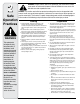
2 Safe Operation Practices WARNING This symbol points out important safety instructions which, if not followed, could endanger the personal safety and/or property of yourself and others. Read and follow all instructions in this manual before attempting to operate this machine. Failure to comply with these instructions may result in personal injury. When you see this symbol.
Operation Maintenance & Storage 1. Do not put hands or feet near rotating parts, in the auger/impeller housing or chute assembly. Contact with the rotating parts can amputate hands and feet. 2. The auger/impeller control lever is a safety device. Never bypass its operation. Doing so makes the machine unsafe and may cause personal injury. 3. The control levers must operate easily in both directions and automatically return to the disengaged position when released. 4.
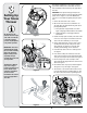
3 Setting Up Your Snow Thrower This Operator’s Manual may cover a range of product specifications. Characteristics and features discussed and/or illustrated in this manual may not be applicable to all models. IMPORTANT: Two replacement auger shear pins are included with this manual (or stowed in the plastic handle panel). Refer to “Augers” section in the Maintenance section for more information regarding shear pin replacement. 1. Remove the unit from the crate or carton. ! 2.
3 CAUTION: Prior to operating your snow thrower, refer to Auger Control Test in Operation section. Read and follow all instructions carefully, and perform all adjustments to verify your snow thrower is operating safely and properly. Setting Up Your Snow Thrower Shear Pin Storage Holes are located in the plastic dash panel for convenient shear pin storage. See Figure 7. IMPORTANT: This unit is shipped with the engine full of oil. After assembly, refer to engine manual for fuel and oil fill-up details.
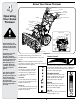
4 Know Your Snow Thrower Drive Control Shift Lever Four-Way Chute Control™ Auger Control Operating Your Snow Thrower Wheel Steering Control Headlight Electric Start Button Gas Cap Fuel Tank Oil Fill Chute Assembly Engine Controls Recoil Starter Handle Electric Starter Outlet WARNING Primer Ignition Key Read, understand, and follow all instructions and warnings on the machine and in this manual before operating.
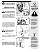
Auger Control Four-Way Chute Control™ #(54% $)2%#4)/.!, #/.42/, !5'%2 #/.42/, #(54% 4),4 $/7. 053( "544/. #(54% 2/4!4% ,%&4 '/ 053( "544/. #(54% 2/4!4% 2)'(4 #(54% 4),4 50 The chute directional control is located on the left side of the dash panel. • To change the direction in which snow is thrown, squeeze the button on the joy-stick and pivot the joy-stick to the right or to the left. The auger control is located on the left handle.
4 Operating Your Snow Thrower Gas & Oil Fill-Up Service the engine with gasoline and oil as instructed in the Tecumseh Engine manual packed separately with your snow thrower. Read instructions carefully. Starting The Engine 1. Attach spark plug wire to spark plug. Make certain the metal loop on the end of the spark plug wire (inside the rubber boot) is fastened securely over the metal tip on the spark plug. 2. Make certain both the auger control and drive control are in the disengaged (released) position.
To Engage Drive 1. With the engine running near top speed, move shift lever to one of six FORWARD positions or two REVERSE positions. Select a speed appropriate for the snow conditions that exist. 2. Squeeze drive control against the right handle and the snow thrower will move. Release it and the drive motion will stop. 3. To turn the unit left or right, squeeze the respective wheel steering control. See Figure 12.
5 Shift Cable If the full range of speeds (forward and reverse) cannot be achieved, refer to the figure to the left and adjust the shift cable as follows: 1. Place the shift lever in the fastest forward speed position. Making Adjustments 2. Loosen the hex nut on the shift cable index bracket. See Figure 14. 3. Pivot the bracket downward to take up slack in the cable. 4. Retighten the hex nut. 5. Check for correct adjustment before operating the snow thrower.
5 You can also check the adjustment as follows: 1. With the snow thrower tipped forward (be certain to drain gasoline or place plastic film under the gas cap if the snow thrower has already been operated), remove the frame cover underneath the snow thrower by removing the self-tapping screws. Refer to Figure 22 in Maintenance section. Making Adjustments 2. With the drive control released, there must be 1/8" clearance between the friction wheel and the drive pulley in all positions of the shift lever. 3.
6 • Some adjustments will have to be made periodically to maintain your unit properly. 3HEAR 0IN 3PACERS • Periodically check all fasteners and make sure these are tight. "EARING Maintaining Your Snow Thrower Engine Refer to the separate Tecumseh Engine manual packed with your unit for all engine maintenance. Lubrication 1.
6 Shave Plate and Skid Shoes The shave plate and skid shoes on the bottom of the snow thrower are subject to wear. Check these periodically and replace as necessary. Maintaining Your Snow Thrower Replacing Skid Shoe 1. Remove four carriage bolts, hex nuts, and washers which attach the two skid shoes to the snow thrower on each side of the housing. See Figure 20. 2. Reassemble new skid shoes with the same hardware. Make certain the skid shoes are adjusted to be level. Figure 20 Replacing Shave Plate 1.
6 Auger Belt 1. Roll auger belt off the pulley as shown in Figure 23. 2. a. Turn the shoulder screw a half a turn and slide it out of the mounting bracket. See Figure 24. b. Unhook spring to release tension on the auger belt. See Figure 24. 3. Remove old belt and replace with new belt wrapping it around the auger pulley. See Figure 25. Maintaining Your Snow Thrower 4. Re-insert shoulder screw into the mounting bracket and tighten to secure. 5. Wrap auger belt behind the idler.
Drive Belt 1. a. Grasp the idler pulley and pivot it toward the right. See Figure 26. Insert a screw driver through aligning holes in both the idler bracket and the engine. This will release tension on drive belt. b. Roll the auger belt off the engine pulley. c. Lift the drive belt off engine pulley. See Figure 26. 2. Slip the drive belt off the pulley and between friction wheel and friction wheel disc. See Figure 27. # " 6 Maintaining Your Snow Thrower 3.
7 Off-Season Storage If the snow thrower will not be used for 30 days or longer, or if it is the end of the snow season when the last possibility of snow is gone, the equipment needs to be stored properly. Follow storage instructions below to ensure top performance from the snow thrower for many more years. Preparing Engine Preparing Snow Thrower NOTE: Refer to the engine manual for more detailed information on preparing the snow thrower engine for storage.
Problem Remedy Cause 1. Choke not in ON position. 1. Move choke to ON position. 2. Spark plug wire disconnected. 2. Connect wire to spark plug. 3. Fuel tank empty or stale fuel. 3. Fill tank with clean, fresh gasoline. 4. Engine not primed. 4. Prime engine as instructed in “Operating Your Snow Thrower”. 5. Faulty spark plug. 5. Clean, adjust gap, or replace. 6. Blocked fuel line. 6. Clean fuel line. 7. Safety key not in ignition on engine. 7. Insert key fully into the switch. 1.
1 38 2 3 15 17 18 5 4 7 6 16 9 53 54 13 11 10 12 2 52 22 55 59 19 35 14 55 35 24 21 57 56 57 23 37 36 42 43 25 32 41 43 56 33 34 28 26 29 30 42 45 27 44 48 40 46 20 49 39 49 48 49 46 51 58 2 8 50 47 20 31
2. 712-04065 Flange Lock Nut 32. 721-0325 Plug 3. 756-0981B Flat Idler Pulley 33. 736-3084 Flat Washer 4. 710-0347 Hex Bolt, 3/8-16 x 1.75 34. 715-04021 Dowel Pin 5. 790-00080A Auger Idler Bracket 35. 684-04108 Spiral Assembly- RH 6. 736-0174 Wave Washer 36. 618-0123 Reducer Hsg.-RH (Incl Ref. 44-45) 7. 738-0281 Shoulder Screw 37. 717-0528A Worm Gear, 20T 8. 738-0143 Shoulder Screw 38. 725-0157 Cable Tie 9. 790-00075 Bearing Housing 39. 738-04124A Shear Pin 10.
22
738-04194 34. 790-00155 Joystick Bracket 3. 731-04894B Lock Plate 35. 710-04187 Hi-Lo Screw, 1/4-15 x 0.5 4. 711-04287 Pivot Rod 36. 984-04116B 4-Way Chute Control™ Assembly 5. 735-0199A Rubber Bumper 37. 749-04191 Upper Handle LH 6. 710-04354 Screw, 1/4-20 x.375 38. 710-04326 Screw, #8-16 x 0.50 7. 731-04896A Clutch Lock Cam 39. 732-04219A Clutch Lock Spring 8. 712-04081A Shoulder Nut, 1/4-20 40. 731-04954 Steering Control 9. 725-04314 Wire Harness (Not Shown) 41.
18 54 57 40 63 65 52 71 51 59 49 1 62 63 56 55 3 55 11 2 64 47 48 34 67 29 7 28 4 59 38 1 46 66 1 53 50 77 78 19 58 76 16 15 27 38 68 6 17 12 13 44 24 69 A 45 72 22 23 20 8 74 22 24 26 21 12 9 25 75 73 69 43 14 15 1 16 13 38 41 42 25 67 10 26 32 40 37 30 60 6 17 70 31 61 35 36 15 1 33 16 5 42 79 A 81 80 81 82 39 1 24 34
Drive Shaft Assembly 42. 684-04159 Friction Wheel Assembly 3. 732-0705 Cable Guide 43. 716-0136 Retainer Ring 4. 711-1268B Actuator Shaft 44. 726-0221 Speed Nut 5. 746-04229 Drive Clutch Cable 45. 790-00183 Wheel Drive Frame 6. 732-04345 Extension Spring 46. 756-04109 Auger Pulley 7. 790-00207A Drive Clutch Cable Guide Bracket 47. 736-0505 Flat Washer 8. 684-04156 Shift Rod Assembly 48. 710-1245B Hex Bolt, 5/16-24 x 0.875 9. 750-04474 Axle Support Tube 49.
NOTES Use this page to make notes and write down important information.
MANUFACTURER’S LIMITED COMMERCIAL WARRANTY FOR: The limited warranty set forth below is given by Cub Cadet LLC with respect to new merchandise used for commercial purposes and purchased and used in the United States and/or its territories and possessions, and by MTD Products Limited with respect to new merchandise purchased and used in Canada and/or its territories and possessions (either entity respectively, “Cub Cadet”). c.
MANUFACTURER’S LIMITED WARRANTY FOR The limited warranty set forth below is given by Cub Cadet LLC with respect to new merchandise purchased and used in the United States, its possessions and territories, and by MTD Products Limited with respect to new merchandise purchased and used in Canada and/or its territories and possessions.