
Operator`s manual


Section5: Maintenance
_ eforeinspecting,cleaningorservicing themachine,shutoffengine,waitformovingpartstostop,dis- I
connectsparkplugwire andmovewire awayfromsparkplug.
Failureto followtheseinstructionscanresultin seriouspersonalnjuryor propertydamage.
Figure5-17: Dislodginghandlebarstruts.
2. Foldthe top section of the assembly
backward(2, Figure5-16). Guidethe
cablescarefullywhile folding. Besure
not to bend,pinch, or stretchthe cables.
IMPORTANT:To avoid damageto cables,
alwaysfold the top sectionof the
handlebarassemblybackwardandthe
bottom sectionforward.
3. Still supportingthehandlebar
assemblywith onehand,loosenthe two
lower handlebaradjustmentknobs
(3, Figure5-16) just enoughto dislodge
both handlebarstruts (L, Figure5-17)
from the slots (K) inthe wheel bracket
assembly.
NOTE:Thehandlebarheightcould inad-
vertentlychangeif the lower adjustment
knobsareloosenedexcessivelyduring
this step.
4. Carefullyfold the bottom sectionof
the handlebarassemblyforward overthe
engine(4, Figure5-16). Guidethe cables
carefullywhilefolding. Besure not to
bend,pinch, or stretchthe cables;also,
keepcablesawayfrom muffler -- the
outer cablecoveringcanbe burnedifthe
engineis still hot.
5. To unfold handlebarassembly,
performfolding stepsin reverseorder.
PINIONGEARSERVICE
Themowerdrive wheels(rearwheels)
eachcontaina pinion gear. Thisgear
transfersdrive powerto the wheelswhich
propelsthe mowerforward. It is very
importantto keeptheseinternalparts
clean. Thefollowing procedureexplains
how to disassemble,cleanand reassem-
blethemowerdrive wheels. Conductthis
maintenanceonthe pinion gearsafter
every50 operatinghours.
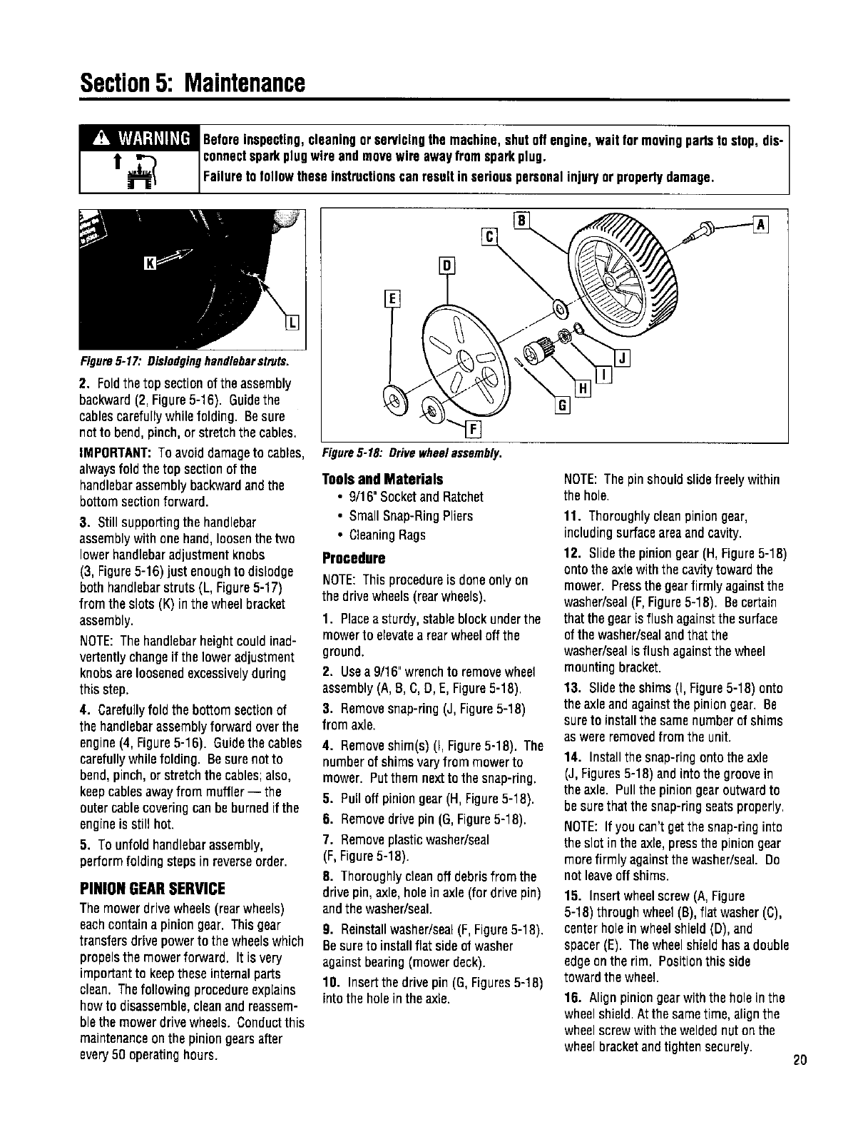
Figure5-18: Drivewheelassembly.
Toolsand Materials
• 9/16" SocketandRatchet
• Small Snap-RingPliers
• CleaningRags
Procedure
NOTE:Thisprocedureis doneonly on
the drivewheels(rearwheels).
1. Placeasturdy, stableblockunderthe
mowerto elevatea rearwheeloff the
ground.
2. Usea 9/16"wrenchto removewheel
assembly(A, 8, C,D,E, Figure5-18).
3. Removesnap-ring (J, Figure5-18)
from axle.
4. Removeshim(s) (I, Figure5-18). The
numberof shims varyfrom mowerto
mower. Putthem nextto thesnap-ring.
5. Pulloff piniongear(H, Figure5-18).
6. Removedrive pin (G,Figure5-18).
7. Removeplasticwasher/seal
(F,Figure5-18).
8. Thoroughlycleanoff debrisfrom the
drive pin, axle,holein axle(for drive pin)
andthe washer/seal.
9. Reinstallwasher/seal(F,Figure5-18).
Besure to installflat side of washer
againstbearing(mowerdeck).
10. Insertthe drive pin (G,Figures5-18)
intothe holein the axle.
NOTE:Thepin should slidefreelywithin
the hole.
11. Thoroughlycleanpinion gear,
including surfaceareaand cavity.
12. Slidethe pinion gear(H,Figure5-18)
onto the axlewith the cavitytowardthe
mower. Pressthe gearfirmly againstthe
washer/seal(F,Figure5-18). Becertain
that the gearLsflush againstthe surface
of the washer/sealandthat the
washer/sealisflush againstthe wheel
mountingbracket.
13. Slidethe shims (I, Figure5-18) onto
the axleandagainstthe piniongear. Be
sureto installthe samenumber of shims
as wereremovedfrom the unit.
14. Installthe snap-ringonto the axle
(J,Figures5-18) andinto the groovein
the axle. Pullthe piniongearoutwardto
besurethatthe snap-ringseatsproperly.
NOTE: If you can't getthe snap-ringinto
the slot in the axle,pressthepinion gear
morefirmly againstthe washer/seal. Do
not leaveoff shims.
15. Insert wheelscrew (A,Figure
5-18) through wheel(B),flat washer(C),
centerholein wheelshield (D), and
spacer(E). Thewheelshieldhas adouble
edgeonthe rim. Positionthis side
towardthewheel.
16. Align piniongearwith the holeinthe
wheelshield.At the sametime, alignthe
wheelscrew with the weldednut on the
wheel bracketandtightensecurely.
2O