Safe Operation Practices • Contents of Carton • Assembly • Adjustments & Operation • Maintenance Warranty Operator’s Manual 45” Snow Thrower Attachment — Model 190-353-100 WARNING READ AND FOLLOW ALL SAFETY RULES AND INSTRUCTIONS IN THIS MANUAL BEFORE ATTEMPTING TO OPERATE THIS MACHINE. FAILURE TO COMPLY WITH THESE INSTRUCTIONS MAY RESULT IN PERSONAL INJURY. CUB CADET LLC, P.O. BOX 361131 CLEVELAND, OHIO 44136-0019 Printed In USA Form No.
1 To The Owner Thank You Thank you for purchasing a Cub Cadet snow thrower attachment. It was carefully engineered to provide excellent performance when properly operated and maintained. Please read this entire manual prior to operating the equipment. It instructs you how to safely and easily set up, operate and maintain your machine. Please be sure that you, and any other persons who will operate the machine, carefully follow the recommended safety practices at all times.
Important Safe Operation Practices 2 WARNING! This symbol points out important safety instructions which, if not followed, could endanger the personal safety and/or property of yourself and others. Read and follow all instructions in this manual before attempting to operate this machine. Failure to comply with these instructions may result in personal injury. When you see this symbol.
8. 4. Do not operate machine while under the influence of alcohol or drugs. 5. Muffler and engine become hot and can cause a burn. Do not touch. 6. Exercise extreme caution when operating on or crossing gravel surfaces. Stay alert for hidden hazards or traffic. Do not carry passengers. 7. Exercise caution when changing direction and while operating on slopes. 8. Do not clear snow across the face of slopes; go up and down. Exercise extreme caution when operating on slopes.
Clearing A Clogged Discharge Chute 5. Snow thrower shave plates and skid shoes are subject to wear and damage. For your safety protection, frequently check all components and replace with original equipment manufacturer’s (O.E.M.) parts only. “Use of parts which do not meet the original equipment specifications may lead to improper performance and compromise safety!” 6. Check clutch controls periodically to verify they engage and disengage properly and adjust, if necessary.
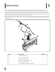
3 Contents of Carton This section will help you to become familiar with the components of the 45” Snow Thrower Attachment, Model 190-353. Select a firm level surface that is large enough to accommodate both the snow thrower assembly and the tractor with front hitch assembly. After removing the upper crating material, remove the hardware pack and carefully roll the snow thrower assembly rearward so that it rests on its bottom.
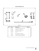
Contents of Hardware Pack 3 1 6 4 7 8 2 5 Figure 3-2 REF. PART # DESCRIPTION QUANTITY 1 710-3022 Hex Cap Screw, 3/8-16 X 2.75 Lg GR5 2 2 712-0431 Hex Flange Lock Nut, 3/8-16 2 3 750-0748 Spacer, 3/8 ID x 1.0 OD x 1.
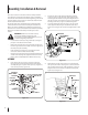
4 Assembly, Installation & Removal This section contains instructions for final assembly of the 45” Snow Thrower, and the quick attachment steps for installation and removal of the snow thrower. Before beginning, select a firm and level surface large enough to accommodate both the snow thrower attachment and tractor. 2.
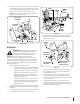
5. Remove the two socket head screws from the split locking collar assembly (6, Figure 3-2) and install the collar onto the bottom of the piston of the front hitch lift cylinder. Secure with the two socket head screws (See Figure 4-4). SHAFT COVER COVER SLOT NOTE: If necessary, use the tractor hydraulic system to slightly extend the cylinder piston. FEMALE HALF SHAFT HITCH LIFT CYLINDER CYLINDER PISTON MALE HALF SHAFT CABLE TIE 4.
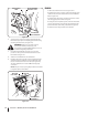
RH ATTACHMENT BRACKET W / PIN FRONT HITCH YOKE REMOVAL 1. Move the snow thrower to its storage location. 2. Compress the auto-lock collar of the snow thrower drive shaft and disconnect the shaft from the tractor PTO shaft. Refer to Figure 4-8. 3. Pull the hitch support pins outward and rotate to lock in the disengaged position. Refer to Figure 8. 4.
5 Adjustments, Controls & Operation ADJUSTMENTS Drift Cutters WARNING! If the snow thrower is to be used on gravel surfaces, use extreme caution to avoid picking up gravel with the shave plate or auger. Loose gravel can damage the auger or housing, and could be thrown at high speed by the impeller— causing possible injury to bystanders or damage to surrounding objects. Skid Shoe Adjustment The skid shoes are mounted on each side of the auger housing.
CONTROLS OPERATION The thrower controls are conveniently located to be operated from the operator’s position on the tractor. The following steps describe methods for safe and proper operation of this snow thrower. Refer to “SAFE OPERATION PRACTICES” on page 3 of this manual for additional safe operating practices. 1. 2. 3. Lift Lever: The tractor hydraulics and front hitch system are used to raise or lower the snow thrower.
d. Fill the tractor’s fuel tank outdoors. Avoid spilling fuel onto the engine or any other source of heat or combustion. Do not fill the tank while the engine is running. Wipe up any spilled fuel before starting the engine. 3. 4. SPECIAL PRECAUTIONS WARNING! If the snow thrower becomes plugged with snow or jammed due to hitting a foreign object, immediately disengage the PTO to stop the snow thrower, then stop the tractor engine. If plugged, SAFELY (see below) clear the chute before resuming operation.
6 Maintenance During Seasonal Usage This section describes maintenance procedures designed to keep your snow thrower in good operating condition. Shave Plate And Skid Shoes The shave plate and skid shoes on the bottom of the snow thrower housing are subject to wear. They should be periodically checked for wear and replaced when necessary. Failure to do so will result in damage to the housing. Refer to Figure 7-1. Replace the shave plate as follows: a.
Lubrication Off-Season Storage 1. The auger gear box is lubricated with grease at the factory and is neither externally serviceable, nor requires checking. If disassembled for any reason, lubricate with 2 ounces (by weight) of Shell Alvania grease, part number 737-0168A. Before reassembling, remove all old sealant and apply Loctite Ultra Grey (759-3746) sealant, or equivalent, to the housing halves.
CUB CADET LLC MANUFACTURER’S LIMITED WARRANTY FOR SERIES 3000 TRACTORS IMPORTANT: To obtain warranty coverage owner must present an original proof of purchase and applicable maintenance records to the servicing dealer. Please see the operator’s manual for information on required maintenance and service intervals. In the U.S.A.: Check your Yellow Pages, or contact Cub Cadet LLC at P.O. Box 361131, Cleveland, Ohio 44136-0019, call 1-877-282- 8684 or log on to our website at www.cubcadet.com.