
Manual


HYDRO. DRIVE AND BRAKE SYSTEM
83
Brakes
NOTE: The brakes may be repaired in the tractor, using
procedures shown on the bench.
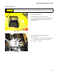
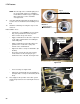
1. The brake yoke is located on the right side of the tran-
saxle. See Figure 5.65.
• The heavy actuator spring connects to the top hole
on the brake arm.
• The light return spring draws the brake arm to the
OFF position.
• Remove the cotter pin and loosen or tighten the
castle nut to adjust the brakes. Use a 9/16” wrench
to set a 0.015” (0.381mm) gap.
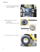
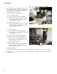
2. There are two main reasons to remove the caliper: to
replace the pads, or to free stuck parts.
3. Loosen both brake yoke bolts using a 3/8” wrench.
See Figure 5.66.
4. Slip the return-to-neutral (r-t-n) spring off of the
spacer on the front bolt.
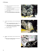
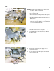
5. The yoke and outer pad will separate from the tran-
saxle. See Figure 5.67.
Figure 5.65
Brake arm
Brake yoke
Return spring
Actuator spring hooks here
Castle nut
Cotter pin
Figure 5.66
Figure 5.67
Brake rotor
Brake yoke
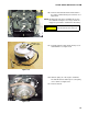
Short r-t-n
spring
Grooved spacer
Installed r-t-n spring
fits into groove in spacer