Operator’s Manual SERIES 1500 Hydrostatic Lawn Tractor Models SLT1550 SLT1554 IMPORTANT: READ SAFETY RULES AND INSTRUCTIONS CAREFULLY Warning: This unit is equipped with an internal combustion engine and should not be used on or near any unimproved forest-covered, brush-covered or grass-covered land unless the engine’s exhaust system is equipped with a spark arrester meeting applicable local or state laws (if any).
TABLE OF CONTENTS Content Important Safe Operation Practices Slope Gauge Tractor Set-up Know Your Lawn Tractor Operating Your Lawn Tractor Making Adjustments Maintaining Your Lawn Tractor Service Page 3 7 8 9 12 17 19 25 Content Off-season Storage Maintenance Schedule Maintenance Log Troubleshooting Attachments & Accessories Specifications Replacement Parts Warranty Information Page 29 30 31 32 33 35 34 37 FINDING MODEL NUMBER This Operator’s Manual is an important part of your new lawn tractor.
SECTION 1: IMPORTANT SAFE OPERATION PRACTICES WARNING: This symbol points out important safety instructions which, if not followed, could endanger the personal safety and/or property of yourself and others. Read and follow all instructions in this manual before attempting to operate this machine. Failure to comply with these instructions may result in personal injury. When you see this symbol—heed its warning.
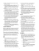
. Follow the manufacturer’s recommendations for wheel weights or counterweights to improve stability. 5. Use extra care with grass catchers or other attachments. These can change the stability of the machine. 6. Keep all movement on the slopes slow and gradual. Do not make sudden changes in speed or direction. Rapid engagement or braking could cause the front of the machine to lift and rapidly flip over backwards which could cause serious injury. 7. Avoid starting or stopping on a slope.
e. Extinguish all cigarettes, cigars, pipes and other sources of ignition. f. Never fuel machine indoors. g. Never remove gas cap or add fuel while the engine is hot or running. Allow engine to cool at least two minutes before refueling. h. Never over fill fuel tank. Fill tank to no more than ½ inch below bottom of filler neck to allow space for fuel expansion. i. Replace gasoline cap and tighten securely. j. If gasoline is spilled, wipe it off the engine and equipment. Move unit to another area.
For safety protection, frequently check components and replace immediately with original equipment manufacturer’s (O.E.M.) parts only, listed in this manual. “Use of parts which do not meet the original equipment specifications may lead to improper performance and compromise safety!” 12. Do not change the engine governor settings or overspeed the engine. The governor controls the maximum safe operating speed of the engine. 13. Maintain or replace safety and instruction labels, as necessary. 14.
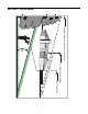
SECTION 2: SLOPE GAUGE OR A CORNER OF A BUILDING OR A FENCE POST PE S A SLO E RE P R E S ENT D LIN O N G D OTTE L &OLD A 3IGHT AND HOLD THIS LEVEL WITH A VERTICAL TREE 7
SECTION 3: TRACTOR SET-UP Gas and Oil Fill-up Attaching The Steering Wheel The gasoline tank is located under the fender and has a capacity of three and-a-half gallons. Unthread the fuel cap by turning it counterclockwise. Use only clean, fresh (under 30 days old), unleaded gasoline. Fill tank to no more than four inches below the top of the filler neck to allow space for fuel expansion. Do not overfill. • • WARNING: Use extreme care when • handling gasoline.
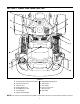
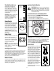
SECTION 4: KNOW YOUR LAWN TRACTOR A G B H C I J K D L E F M Figure 2 A B C D E F G Systems Indicator Monitor/Hour Meter Throttle Control Lever Choke Control Parking Brake Lever Seat Adjustment Lever Fuel Tank Cap Ignition Switch Module H I J K L M PTO (Blade Engage) Knob Brake Pedal Drive Pedal Cruise Control Lever Deck Lift Lever Cup Holder NOTE: Any reference in this manual to the RIGHT or LEFT side of the tractor is observed from operator’s position.
Throttle Control Lever The throttle control lever is located on the left side of the tractor’s dash panel. This lever controls the speed of the engine. When set in a given position, the throttle will maintain a uniform engine speed. Ignition Switch Module Fast Position WARNING: Never leave a running machine unattended. Always disengage PTO, move shift lever into neutral position, set parking brake, stop engine and remove key to prevent unintended starting.
Systems Indicator Monitor / Hour Meter Electric PTO / Blade Engage Knob To engage the power to the cutting deck or other (separately available) attachments, pull outward on the PTO/Blade Engage knob. Push the PTO/ Blade Engage knob inward to disengage the power to the cutting deck other (separately available) attachments. 42.0 NOTE: The PTO/Blade Engage knob must be in the disengaged (OFF) position when starting the engine.
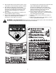
SECTION 5: OPERATING YOUR LAWN TRACTOR WARNING: Use extreme caution while operating the tractor in the REVERSE CAUTION MODE. Always look down and behind before and while backing. Do not operate the tractor when children or others are around. Stop the tractor immediately if someone enters the area. WARNING AVOID SERIOUS INJURY OR DEATH • • • • • • • • • • • • GO UP AND DOWN SLOPES, NOT ACROSS. AVOID SUDDEN TURNS. DO NOT OPERATE THE UNIT WHERE IT COULD SLIP OR TIP.
Setting the Gauge Wheels • If the gauge wheels have excessive clearance with the surface below, lower the wheels to the index hole that provides the approximate 1/2" clearance as described above. Refer to Leveling the Deck on page 17 of this manual for more detailed instructions regarding various deck adjustments. Select the height position of the cutting deck by placing the deck lift lever in any of the six different cutting height notches on the right fender.
Engaging the Parking Brake • To engage the parking brake: • Fully depress the brake pedal and hold it while gently pushing the parking brake lever downward. • Hold the parking brake lever down while removing your foot from the brake pedal. • Once engaged, the parking brake lever and the brake pedal will lock in the “down” position. To disengage the parking brake: • IMPORTANT: Do NOT attempt to change the direction of travel when the tractor is in motion.
• • Depress the brake pedal to disengage the cruise control and stop the tractor. • Lightly depress the drive pedal. To change the direction of travel to reverse when operating with cruise control, depress the brake pedal to disengage the cruise control and bring the tractor to a complete stop. Then slowly depress the rear portion of the drive pedal with the ball of your foot to travel in reverse. NOTE: The transmission will NOT engage when the hydrostatic bypass rod is pulled out.
Mowing • WARNING: To help avoid blade contact or a thrown object injury, keep bystanders, helpers, children and pets at least 75 feet from the machine while it is in operation. Stop machine if anyone enters the area. • This tractor is equipped with one of Cub Cadet’s quality cutting decks. The following information will be helpful when using the cutting deck with your tractor. • • WARNING: Plan your mowing pattern to avoid discharge of materials toward roads, sidewalks, bystanders and the like.
SECTION 6: MAKING ADJUSTMENTS WARNING: Never attempt to make any • adjustments while the engine is running, except where specified in the operator’s manual. • Leveling the Deck Tighten the inner hex nuts front against the front hanger bracket to raise the front of the deck; loosen the hex nuts to lower the front of the deck. See Figure 9. Retighten the two lock nuts against the inner hex nuts when proper adjustment is achieved.
Parking Brake Adjustment WARNING: Never attempt to adjust the brakes while the engine is running. Always disengage PTO, stop engine and remove key to prevent unintended starting. If the tractor does not come to a complete stop when the brake pedal is completely depressed, or if the tractor’s rear wheels can roll with the parking brake applied, the brake is in need of adjustment. The brake disc can be found on the right side of the transmission in the rear of the tractor. Adjust if necessary as follows.
SECTION 7: MAINTAINING YOUR LAWN TRACTOR NOTE: Refer to Maintenance Chart on page 30 for a TEMPERATURE / OIL VISCOSITY CHART reference of recommended maintenance intervals. WARNING: Before performing any maintenance or repairs, disengage PTO, set parking brake, stop engine and remove key to prevent unintended starting.
IMPORTANT: The engine may overheat and/or damage may result if the oil level is below the ADD or over the FULL on the dipstick. • Oil Fill Cap / Dipstick Reinstall the oil fill cap/dipstick securely onto the oil fill tube. IMPORTANT: The oil fill cap/dipstick must be installed securely onto the tube at all times when the engine is operating. Severe engine damage could result from failure to do so.
• • Service Paper Element Slowly pour oil into the fill tube. Fill the crankcase until the oil level reaches the full (F) mark on the dipstick (Refer to Page 19). Reinstall the oil fill cap/dipstick securely into the oil fill tube. The paper element should be replaced at least every 100 hours of operation. Replace more frequently if the tractor is operated under extremely dusty conditions.
• 1. Drive the tractor to a level, clear spot on your lawn, near enough to a water sillcock (spigot) for your garden hose to reach. Check the gap using a feeler gauge and adjust, if necessary, by carefully bending the ground electrode. See Figure 14. Set the spark plug gap to .76 mm (0.030 in.). IMPORTANT: Make certain the tractor’s discharge chute is directed AWAY from your house, garage, parked cars, etc. Feeler Gauge 2. Disengage the PTO (Blade Engage), set the parking brake and stop the engine. 3.
Lubrication Carburetor WARNING: Before lubricating, repairing, or inspecting, always disengage PTO, set parking brake, stop engine and remove key to prevent unintended starting. NOTE: Carburetor adjustments should be made only after the engine has warmed up. The engines on Cub Cadet Series 1500 tractors are equipped with a fixed main jet carburetor. Engine Carburetors are equipped with a idle speed adjustment screw and a low idle fuel mixture screw.
Adjustment Lean NOTE: Engines may have a fixed idle or limiter cap on the idle fuel adjusting screw. Step 2 can only be performed within the limits allowed by the cap. Adjust to Midpoint 1. Start the engine and run at half throttle for five to 10 minutes to warm up. The engine must be warm before performing steps 2 and 3. 2. Low Idle Fuel Screw Setting: Place the throttle into the “idle” or “slow” position.
SECTION 8: SERVICE Tires • WARNING: Never exceed the maximum inflation pressure shown on the sidewall of the tire. Place a block of wood between the center deck housing baffle and the cutting blade to act as a stabilizer. See Figure 18. Hex Flange Nut Wood Block The recommended operating tire pressure is approximately 10 psi for the rear tires and 14 psi for the front tires. Refer to the tire sidewall for exact tire manufacturer’s recommended or maximum psi. Do not overinflate.
Battery Cutting Deck Removal The battery is sealed and is maintenance-free. Acid levels cannot be checked and fluid can not be added. To remove the cutting deck, proceed as follows: • Place the PTO/Blade Engage knob in the disengaged (OFF) position and engage the parking brake. • Lower the deck by moving the deck lift lever into the bottom notch on the right fender. • Remove the deck belt from around the tractor’s electric PTO clutch (refer to Changing the Deck Belt).
Hydrostatic Transmission substitute (non-OEM) V-belt can be dangerous by not disengaging completely. For a proper working machine, use factory approved belts. Keep the area around the transmission cooling fan free of grass and debris at all times. The hydrostatic transmission is sealed at the factory and is maintenance free. The fluid level cannot be checked and on most models, cannot be changed.
• • NOTE: The idler pulley(s) may have to be loosened, but not removed, in order to remove the belt from around them. Grasp the ratchet’s handle and pivot it to relieve tension on the belt. With belt tension relieved, carefully remove the belt from around the left-hand spindle pulley. • IMPORTANT: Carefully allow the ratchet to pivot rearward before removing it from the square hole. • • Route the new belts (deck belt first) as shown on the following page. Remount the belt guards removed earlier.
SECTION 9: OFF-SEASON STORAGE Clean and lubricate the tractor as instructed in Section 7: MAINTAINING YOUR LAWN TRACTOR on page 19 of this manual before storing for an extended period. To empty the system, run the engine until the tank and system are empty. WARNING: Drain fuel only into an approved container outdoors, away from an open flame. Allow engine to cool. Extinguish cigarettes, cigars, pipes, and other sources of ignition prior to draining fuel.
SECTION 10: MAINTENANCE CHART Before Each Use After Initial 24 Hours Every 10 Hours Clean Hood/Dash Louvers Check Engine Oil Level Clean and Re-oil Air Filter’s Foam Precleaner Replace Air Filter Element Change Engine Oil & Filter Clean Battery Terminals Lube Front Axles and Rims Clean Engine Cooling Fins Lube Front Deck Wheels Lube Deck Spindles Lube Pedal Pivot Points Check Spark Plug 30 Every 25 Hours Every 100 Hours Every Season Prior to Storing
SECTION 11: MAINTENANCE LOG Please keep a record of the maintenance performed on your tractor.
SECTION 12: TROUBLESHOOTING Trouble Possible Cause(s) Corrective Action Engine fails to start PTO/Blade Engage knob engaged. Parking brake not engaged. Spark plug wire(s) disconnected. Throttle control lever not in correct starting position. Choke not activated Fuel tank empty, or stale fuel. Blocked fuel line. Faulty spark plug. Engine flooded. Unit running with CHOKE activated. Spark plug wire(s) loose. Blocked fuel line or stale fuel. Place knob in disengaged (OFF) position. Engage parking brake.
SECTION 13: ATTACHMENTS & ACCESSORIES The following attachments and accessories are compatible for Series 1500 Lawn Tractors. See your Cub Cadet dealer or the retailer from which you purchased your tractor for information regarding price and availability. NOTE: Cub Cadet Series 1500 lawn tractors are NOT designed for use with any type of ground-engaging attachments (e.g. tiller or mulboard plow). Use of this type of equipment WILL void the tractor’s warranty.
SECTION 14: REPLACEMENT PARTS NOTE: Download a complete Cub Cadet Series 1500 Parts Manual free of charge at www.cubcadet.com or phone (800) 800-7310 to purchase a Parts Manual (Form No. 769-01652C). SLT1050 RC12YC 32-083-03-S 32-083-05-S 52-050-02-S 25-050-22-S 754-0461 754-04077 742-04053A (Qty.
SECTION 15: SPECIFICATIONS* SLT1550 SLT1554 Capacities Fuel Tank 13.2 liters (3.5 gallons) 13.2 liters (3.5 gallons) Engine Crankcase (w/ filter) 1.7 liters (57.5 oz.) 1.7 liters (57.5 oz.) Transmission 2.25 liters (76 oz.) 2.25 liters (76 oz.) Make and Model Hydro-Gear 0510 Hydro-Gear 0510 Gear Ratio 22.2:1 22.2:1 Hydrostatic Transmission Forward Speed 0 m.p.h. - 5.2 m.p.h. 0 m.p.h. - 5.2 m.p.h. Reverse Speed 0 m.p.h. - 2.3 m.p.h. 0 m.p.h. - 2.3 m.p.h.
NOTES 36
CALIFORNIA EMISSION CONTROL WARRANTY STATEMENT YOUR WARRANTY RIGHTS AND OBLIGATIONS The California Air Resources Board and Cub Cadet LLC are pleased to explain the evaporative emission control system warranty on your 2006 lawn mower. In California, new lawn mower must be designed, built and equipped to meet the State’s stringent anti-smog standards.
KOHLER CO. FEDERAL AND CALIFORNIA EMISSION CONTROL SYSTEMS LIMITED WARRANTY UTILITY AND LAWN AND GARDEN ENGINES The U.S. Environmental Protection Agency (EPA), the California Air Resources Board (CARB), and Kohler Co. are pleased to explain the Federal and California Emission Control Systems Warranty on your small off-road equipment engine. For California, engines produced in 1995 and later must be designed, built and equipped to meet the state’s stringent anti-smog standards.
CUB CADET LLC MANUFACTURER’S LIMITED WARRANTY FOR SERIES 1000 & SERIES 1500 TRACTORS IMPORTANT: To obtain warranty coverage owner must present an original proof of purchase and applicable maintenance records to the servicing dealer. Please see the operator’s manual for information on required maintenance and service intervals. Without limiting the foregoing, this limited warranty does not provide coverage in the following cases: a.
CUB CADET LLC, P.O.