Service Manual 1000/1500 Series Riding Tractors NOTE: These materials are for use by trained technicians who are experienced in the service and repair of outdoor power equipment of the kind described in this publication, and are not intended for use by untrained or inexperienced individuals. These materials are intended to provide supplemental information to assist the trained technician. Untrained or inexperienced individuals should seek the assistance of an experienced and trained professional.
Table of Contents 1. INTRODUCTION ........................................................................................................................ 1 2. NEW HOOD DESIGN ................................................................................................................. 3 3. HOOD PANEL REMOVAL: 1500 SERIES ................................................................................ 5 4. HOOD AND HINGE REMOVAL: 1500 SERIES ........................................................
2
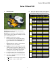
Series 1000 and 1500 Series 1000 and 1500 1. INTRODUCTION 1.5. Refer to the table provided for engine applications in the 1000 series range. See Figure 1.5. 1000 Series Engine Applications Year Model # Factory # Engine 2001 1027 13A-328-101 9.0 HP BS 1170 13CD608G101 17.5 HP BS 1180 13AT608H101 18 HP BS 1212 14AJ808H101 21 HP BS Disclaimer: This service manual is intended to be used by trained technicians.
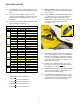
Series 1000 and 1500 1.6. Decks: Cutting decks ranging in width from 38” to 54” have been used on the 1000 Series platform. 1.9. 1.7. There have been multiple versions of some decks, most particularly the 42”. Check the serial number when researching for parts or service information. 1.8. The deck size is identified by the 8th digit of the factory number: See Figure 1.8. 1.10. A Two-belt CVT system driving an MTD singlespeed transaxle is presently used only on the LT1040 model.
Series 1000 and 1500 1.15. A Hydro-Gear 314-0610 hydrostatic transaxle with a different final drive ratio is used on LT models having 22” rear tires. Hydrostatic transaxles have a rocker pedal to control forward and reverse direction and speed. See Figure 1.15. 2. NEW HOOD DESIGN 2.1. Early 1000 and 1500 Series tractors used a variety of steel hoods and side panels. Later ones resembled those used on the 2000 and 2500 Series tractors. 2.2.
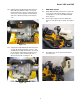
Series 1000 and 1500 2.4. • The 1000 Series hood can be easily removed: See Figure 2.4. A pair of gas charged cylinders provide lift assist. See Figure 2.5. Gas lift Cylinders Pivot Rod Figure 2.5 Figure 2.4 2.6. • Disconnect the headlight wires • Release the retaining springs • Align the bolts in the hood with the slots in the hinge. • Lifting the hood off of the tractor. 2.5. The hood used on the 1500 Series tractors for 2005 and 2006 is more substantial than that used on the 1000 Series.
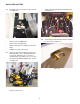
Series 1000 and 1500 2.7. A torsion spring keeps the latch secure until the lower pivot latch is intentionally pulled up, to open the hood. See Figure 2.7. 3.2. Disconnect headlight harness (plugged secured to hood lift cylinder). See Figure 3.2. Headlight Harness Torsion Spring Upper Pivot Latch Cotter Pin Pivot Rod Lower Pivot Latch Figure 3.2 Figure 2.7 3.3. 2.8. The hood latches to a sturdy rod that is mounted to the front of the frame. See Figure 2.8.
Series 1000 and 1500 4. HOOD AND HINGE REMOVAL: 1500 SERIES 4.8. Hood installation notes: See Figure 4.8. NOTE: Use this procedure for more extensive repairs. Typical reasons may include dash panel removal, or the need for more working room than simply removing the hood will provide. 4.1. Remove the battery: See Figure 4.1. Figure 4.8 • Position the hinge support bar over the two spacers that partially cover the threads of the balls that the that hood support struts attach to.
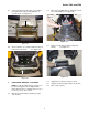
Series 1000 and 1500 5. REAR FENDER REMOVAL 5.1. It is necessary to remove the fender assembly for access to the following service areas: See Figure 5.1. 5.4. Remove the rubber grip from the cutting deck height control handle atop the right rear fender. See Figure 5.4. Figure 5.4 Figure 5.1 5.5.
Series 1000 and 1500 5.7. Remove the four bolts that hold the seat brackets to the frame using a 1/2” wrench. 5.8. Remove the seat to a safe location. 5.9. Remove the hydro control pedal (or speed control pedal on CVT equipped models) using a T40 driver. See Figure 5.9. 5.12. Peel-back the rubber foot pad to reach and remove the carriage bolt. See Figure 5.12. T-40 Screws Figure 5.12 5.13.
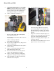
Series 1000 and 1500 5.14. Remove the two screws that were revealed by peeling-back the label. This can be done using a 3/8” wrench. See Figure 5.14. • When installing a large panel, start all of the threaded fasteners, then go back and tighten each after the panel is in position. • Test the operation of all controls and safety features in a safe place, free of obstacles and bystanders before returning the tractor to service. 6. FUEL SYSTEM 6.1.
Series 1000 and 1500 6.5. On current models of the 1000 and 1500 Cub Cadet, the fuel is moved from the tank to the carburetor by a vacuum-driven fuel pump that is mounted to the engine. See Figure 6.5. 6.9. In the event that it is necessary to remove the fuel tank, begin by removing the fenders as described in the REAR FENDER REMOVAL section of this manual. 6.10. Make provisions for draining any fuel that remains in the gas tank: 24” of 1/4” fuel line, and a suitable catch pan will be sufficient.
Series 1000 and 1500 6.15. Remove the plate that supports the seat brackets using a 1/2” wrench. See Figure 6.15. Seat Bracket Plate Figure 6.15 • When the solenoid does not have power, it closes, stopping the flow of fuel. • The solenoid usually emits an audible “click” when power is applied or discontinued. • If the solenoid does not click, it is not working. If it does click, it cannot be assumed to be working properly. 8. FUEL RELATED NO-START ISSUES 8.1.
Series 1000 and 1500 • 9. 9.7. Ether-based starting fluids should not be used, and may void engine warranties if their use is detected. Remove both hinge brackets. See Figure 9.7. Hinge Bracket MUFFLER REMOVAL NOTE: There are a variety of mufflers on this series of tractor depending on the year and engine of the unit. this chapter will cover a few different mufflers to give you the basics of muffler removal on this series. NOTE: For all tractors, remove the bumper first.
Series 1000 and 1500 9.9. Remove the four screws going through the muffler support brackets into the muffler mounting bracket. See Figure 9.9. 9.16. Remove the four screws holding the muffler guard to the front muffler support brackets. See Figure 9.16. Remove these hex screws. (two on each side) Muffler Support Bracket Figure 9.16 Figure 9.9 9.10. The muffler will now slide off of the exhaust pipe(s). NOTE: The rear two screws will be accessible from the top.
Series 1000 and 1500 10.3. Remove the PTO belt from electric PTO clutch. See Figure 10.3. 10.7. Slide the deck forward and release the front stabilizer rod. DO NOT DROP the deck to the ground. See Figure 10.7. Electric PTO clutch Idler (earlier production) Front stabilizer rod Figure 10.3 Figure 10.7 NOTE: On some models you will need to remove the belt guide first. 10.8. Slide the deck toward the right side of he tractor and remove it from under the tractor.
Series 1000 and 1500 11. DECK LIFT SHAFT ASSEMBLY 11.6. With the deck height control lever all the way forward, remove the hairpin clips that secure the deck lift cables to the arms on the deck lift shaft. See Figure 11.6. 11.1. If the deck lift shaft itself requires removal, first remove the cutting deck. 11.2. Remove the fenders as described in the FENDER REMOVAL section of this manual. Deck Lift Cable 11.3.
Series 1000 and 1500 bushing, it should be a dry graphite or PTFE based lube. 11.9. Slide the lift shaft assembly to the right, providing clearance to remove the left end of the shaft from the frame. See Figure 11.9. Lift Shaft • Replace the bushings an E-clips if they show signs of wear. • Reverse the removal process to install the lift shaft. • Connect the cables and install the bushings prior to connecting the tension spring between the lift shaft arm and the transaxle torque bracket. 12.
Series 1000 and 1500 12.4. Disconnect the deck lift assist spring that extends from the deck lift shaft to the transaxle torque bracket using a length of starter rope or a spring tool. See Figure 12.4. 13.3. Remove the rear tires using a 3/4” wrench. See Figure 13.3. Deck Lift Assist Spring Figure 13.3 Figure 12.4 13.4. Remove the handle from the rear fenders using a 3/8” wrench. The screws are accessible from inside the rear fender. See Figure 13.4. 12.5.
Series 1000 and 1500 13.5. Remove the notched plate that the deck height control lever seats against in the fender, using a 1/2” socket. See Figure 13.5. 13.10. Remove the hairpin clip that secures the pin to the lift arm, and remove the cable. 13.11. Installation notes: • Reverse the removal process to install the cables and pulleys. • Because of the dusty environment that many mowers operate in, grease applied to the cable or pulley may accelerate wear rather than prevent it.
Series 1000 and 1500 14.1. Using a work glove or rag, rotate the blades until they are cutting edge tip to cutting edge tip (perpendicular) to the tractor. See Figure 14.1. FRONT TO REAR ADJUSTMENT IMPORTANT: The front of the deck will be between 1/4” and 3/8” lower in the front than the rear of the deck. 14.6. Using a work glove or a rag, rotate the blades until they are parallel with the tractor frame. See Figure 14.6. Blades parallel with frame Figure 14.1 14.2. Measure the outer blade tips to ground.
Series 1000 and 1500 • • For the U-bolt style: 14.11. Loosen both lock nuts securing the adjustment nuts on the front of the deck stabilizer bracket using a two 3/4” wrenches. For the J-bolt Style: 14.15. The J-bolt style stabilizer is adjusted in a similar fashion. Loosen the single lock nut away from the adjustment nut using two 3/4” wrenches. Lock Nut Adjustment Nut Lock Nuts Adjustment Nuts Figure 14.11 Figure 14.15 14.12.
Series 1000 and 1500 15.4. Remove the steering wheel from the steering shaft using a 1/2” wrench. See Figure 15.4. 15.6. Disconnect the rods that connect the Park Brake and Cruise Control mechanisms to the levers on the dash that control those features by removing the hairpin clips. See Figure 15.6. Hairpin clips Figure 15.4 Figure 15.6 15.5. Disconnect the following dash-mounted electrical devices by unplugging the molded connectors: See Figure 15.5. 15.7.
Series 1000 and 1500 • Two hex-head cap screws holding the rear flange of the dash to the frame (1/2” wrench) • Two hex-head cap screws holding the top of the dash to the dash support (3/8” wrench). See Figure 15.9. 16.4. Remove the hair pin clips holding the linkages to the levers in the dash. See Figure 16.4. Hairpin Clips Hex-head cap screw Figure 16.4 16.5. Remove the screw holding the pivot rod in place. See Figure 16.5. Figure 15.9 Pivot Rod Hex Screw 15.10.
Series 1000 and 1500 16.10. Remove the cotter pins in the brake pedal shaft and the drive pedal shafts. See Figure 16.10.. 16.16. Remove the lock nut from the bottom of the steering shaft. Then slide off the steering shaft gear. See Figure 16.16. Cotter Pins Lock Nut Hex Nut Figure 16.10 Figure 16.16 16.11. Slide the drive pedal to the right. The inboard bushing and washer can now be removed. Continue working the drive pedal shaft to the right and slip it out of the unit. 16.17.
Series 1000 and 1500 16.19. Pivot the subframe down. Be careful of the spacer on the bolt and the hex flange bushing for the steering shaft, they will fall out. 17.3. Remove the battery hold-down, remove the battery and the battery tray. See Figure 17.3. 16.20. You now have access to the cruise linkage and cam lock. You also have access the park brake linkage and locking plate. See Figure 16.20. Battery Hold Down Cruise Control Rod. Parking Brake Rod Cam Lock Figure 17.3 17.4.
Series 1000 and 1500 17.6. Using the slack created by taking the belt off the tensioner pulley, slip the belt off of the transaxle input pulley and the upper sheave of the variable speed pulley and remove the belt from the tractor. You may need to remove the transmission input pulley to get enough clearance to remove the belt. See Figure 17.6. 17.8. Lift the sliding center partition of the variable speed pulley as far as it will go.
Series 1000 and 1500 17.11. Disconnect the plug for the PTO clutch wire. It is located on the right side of the tractor, just above the opening in the frame that the wire passes through to reach the PTO clutch. See Figure 17.11. NOTE: On some models you may have to remove the belt guide on the engine. Remove the 1/2” bolt securing the belt guide to the frame on the left hand side and slide the guide out of the hole on the right hand side. See Figure 17.12. PTO clutch plug Bolt Figure 17.11 Figure 17.
Series 1000 and 1500 17.15. Remove the belt from the tractor. NOTE: There were a small number of tractors made using a CVT drive and a 2-speed (L-H-N-R) GT transaxle. The belt must pass over the center mounted gear selector on these models for removal. Remove the knob from the gear selector, and remove the shift gait from the fender assembly to provide clearance. • The tractor’s forward ground speed should vary smoothly between 0 and 5.
Series 1000 and 1500 • loads (from torquing the nut) directly to the pulley, not the adaptor. Remove the battery and battery tray from the tractor. 18.6. Inspect the upper drive belt: See Figure 18.6. 18.8. Repair any problems found. If the upper drive belt is correct and in serviceable condition, reinstall it. If the upper drive belt needs to be replaced, the lower drive belt should be replaced as well. Refer to the “TRACTION DRIVE BELT REPLACEMENT” section of this manual. 18.9.
Series 1000 and 1500 18.11. The empty hole in the double idler bracket should swing through an arc of 1 3/8” when 10 lbs. of force is applied to the drive pedal. See Figure 18.11. 18.15. The forward end of the speed control rod connects to a pin attached to the speed control assembly. NOTE: On 2005 production units you can remove the nut on the ball joint and lift it out of the idler bracket on an angle, then skip to step 15.16. See Figure 18.15. 1 3/8” movement 2005 production Figure 18.11 18.12.
Series 1000 and 1500 19. BRAKE ADJUSTMENT: CVT 19.8. CVT-driven transaxles use a self locking nut on the brake adjustment. See Figure 19.8. 19.1. On CVT-driven lawn and garden tractors, most of the braking force is generated within the transaxle: when the drive pedal is released, the drive ratio changes, slowing the tractor. The brake brings the tractor to a complete stop, and functions as a parking brake. 19.2.
Series 1000 and 1500 19.13. Check the movement of the brake arm: • The brake arm should move forward as the brake is applied. • The return spring should draw the brake arm back against the spacer when the brakes are released. 19.17. Remove the caliper from the transaxle. The brake actuator arm can now be unhooked from the spring that connects it to the linkage. See Figure 19.17. 19.14. Visually check the thickness of the brake pads: they are visible within the caliper. 19.15.
Series 1000 and 1500 19.19. A crease in the brake arm acts as a cam. At rest, the ends of the two pins ride in the peak of the crease: See Figure 19.19. 20. SERVICING THE BRAKE PEDAL SHAFT BUSHINGS: • If there is insufficient travel in the linkage to fully apply the brakes, a simple visual inspection should identify the cause. 20.1. Confirm that the brake pedal is firmly attached to the pedal shaft. See Figure 20.1. Brake Pedal Figure 19.19 • The brake arm pivots on a square-headed stud.
Series 1000 and 1500 20.4. The inboard brake pedal shaft bushing can be removed by removing the cotter pin and washer that secure it. See Figure 20.4. 20.6. Press the brake pedal shaft as far outward as possible, and pry the worn bushing out of the bracket. See Figure 20.6. Bushing Figure 20.4 Figure 20.6 20.5. The brake rod must be disconnected to remove the outboard brake pedal shaft bushing. Remove and discard the cotter pin that holds the brake rod to the brake pedal shaft. See Figure 20.5.
Series 1000 and 1500 21.2. Remove the battery hold down, battery and battery tray from the unit. See Figure 21.2. NOTE: Lubrication with grease may accelerate bushing wear. If lubrication is applied it should be in dry form such as graphite or PTFE (Teflon). 20.8. Secure the inner bushing with a new cotter pin and the flat washer that was previously removed. Battery hold down 20.9. Move the pedal through it’s range of travel to check for binding.
Series 1000 and 1500 21.4. Using a 7/8 socket and extension, remover the nut securing the transmission pulley to the transmission. See Figure 21.4. 21.7. Disconnect the brake linkage where it connects to the brake spring. See Figure 21.7. Transmission pulley Brake linkage Figure 21.7 Figure 21.4 21.8. Use white-out to mark the position of the ferrule on the transmission shift rod. 21.5. Remove the pulley from the unit. 21.6. Support the frame of the unit to allow removal of both rear wheels.
Series 1000 and 1500 21.12. Using a 1/2” socket and 1/2” wrench, remove the four hex nuts securing the transmission to the frame. See Figure 21.12. 22. TRANSAXLE SERVICE AND INTERNALS: CVT • Transaxles needing service within the warranty period qualify for like-kind exchange. • If you are servicing transaxle internals, keep in mind that different transaxles/components have been used over the years. • Carefully compare the transaxle with the illustrated parts list when ordering components. 23.
Series 1000 and 1500 23.4. Remove the electric PTO clutch from the engine crankshaft using a 5/8” wrench. See Figure 23.4. 23.6. Carefully release the spring that maintains tension on the double idler bracket using a length of starter rope or an appropriate tool. See Figure 23.6. 5/8” Head bolt Figure 23.4 Figure 23.6 NOTE: Lower the clutch carefully, keeping track of the hardware on the crankshaft.
Series 1000 and 1500 23.8. Slip the crankshaft pulley down far enough to get the belt off of the pulley, and remove the belt from the crankshaft. See Figure 23.8. 23.10. The belt for the G.T. models of the 1500 Series line is Kevlar wrapped. Substituting the polywrapped belt used on the L.T. models is not recommended, but the Kevlar belt is an acceptable premium upgrade for the L.T. tractors. See Figure 23.10. Stamped Belt Guards Figure 23.
Series 1000 and 1500 23.13. The double idler pivot bracket is held to the frame by the same bolt that holds the fore-most of the two pulleys. The rear pulley can be easily removed from the bracket. It is necessary to take the fenders off to remove the front pulley or the bracket itself. 24.3. There is no adjustment to the relief valve, but full travel of the linkage should be checked if the drive system is losing power or ground speed. See Figure 24.3. 23.14.
Series 1000 and 1500 24.7. Turn-off the engine and allow it to cool before starting to work on the tractor. To gain access to the control linkage, perform the following three steps: 24.15. Set the parking brake, and remove the drive pedal using a T-40 driver. See Figure 24.15. T-40 Screws 24.8. Remove the cutting deck. 24.9. Lift and safely support the rear of the tractor. 24.10. Remove the rear wheels using a 3/4” wrench. 24.11.
Series 1000 and 1500 24.17. Remove the washers and inboard bushings from both shafts. See Figure 24.17. 24.21. Install the drive pedal, tightening the screw that secures it to a torque of 250 in-lbs. 24.22. Move the pedal through it’s range of travel to check for bind. If binding is encountered: • Bind in a portion of the travel may be caused by a bent pedal shaft. • Constant bind is likely to be caused by a bent bracket.
Series 1000 and 1500 25. HYDRO CONTROL ROD ADJUSTMENT • If the unit “creeps” in the neutral position, one of two things may have happened: 1. The hydro control rod has been bent, causing the unit to creep or 2. The neutral position adjustment on the hydro has changed. 25.5. If there is, thread the ferrule up or down the length of the hydro control rod until the post is centered in the hole that it fits into. At this point, the transaxle and the linkage should both be synchronized in neutral.
Series 1000 and 1500 25.8. As the hydro control rod moves back on the input arm, it first moves a ground contact against the reverse safety switch. See Figure 25.8. • If the roller is moved lower, the input arm will move in the direction that causes reverse drive. 25.12. The roller is moved up or down by rotating the house-shaped eccentric that the neutral return arm pivots on. See Figure 25.12. Reverse switch Figure 25.8 25.9.
Series 1000 and 1500 26.2. When properly adjusted, the brake should do two things: it should stop and hold the tractor when applied, and it should not drag when released. 26.9. Insert a .015” feeler gauge between the brake rotor and the outer brake pad. There should be slight drag on the feeler gauge. 26.10. If the feeler gauge is too loose, or will not go in, brake caliper adjustment is necessary. 26.3. To check that the brakes hold the tractor: • Open the relief valve. • Set the parking brake.
Series 1000 and 1500 26.16. If the brakes are dragging or worn, or if the rotor needs to be removed from the shaft disconnect the brake return spring where it attaches to the transmission housing. See Figure 26.16. 26.20. In order to remove the rotor and gain access to the fixed brake pad you will have to pry the retaining clip securing the hydro relief arm to the hydro relief valve shaft. See Figure 26.20. Brake return spring Retaining clip Figure 26.20 Figure 26.16 26.17.
Series 1000 and 1500 26.22. The crease in the brake arm acts as a cam: See Figure 26.22. brakes, a simple visual inspection should identify the cause. 26.31. Confirm that the brake pedal is firmly attached to the pedal shaft. See Figure 26.31. Brake Pedal Figure 26.22 • The brake arm pivots on a square-headed stud. • The two pins are forced against the backing plate when force is applied to the arm. • Figure 26.31 26.32.
Series 1000 and 1500 27.3. Remove and discard both cotter pins that secure the brake pedal shaft and the hydro drive pedal shaft to the frame. See Figure 27.3. 27.6. Clean any corrosion or dirt from the surfaces where the pedal shafts contact the bushings, and slip the new bushings into place. See Figure 27.6. Cotter pins Clean Figure 27.3 Figure 27.6 27.4. Remove the large washers and inner bushings from each shaft. NOTE: Lubrication with grease may accelerate bushing wear.
Series 1000 and 1500 will fill the over-flow reservoir, but will not add to the level of fluid in the transaxle. 28.2. Because the transaxle dissipates heat through air-cooling of the housing, it must be kept clean of dirt and debris, and the cooling fan should be replaced immediately if damaged. NOTE: This oil (fluid) should not have to be changed in the normal service life of the transaxle unless it develops a leak or becomes contaminated. 28.3.
Series 1000 and 1500 • Repeat as necessary until the transaxle operates normally. 29.8. Disconnect the front of the brake rod from the brake pedal shaft by removing the cotter pin, and pulling the “L” at the forward end of the rod out of the hole in the brake pedal shaft. See Figure 29.8. 28.13. Any service beyond fluid change requires removal substantial disassembly of the transaxle. Refer to Hydro-Gear manual BLN-52261 for complete repair instructions. 29.
Series 1000 and 1500 29.13. Draw the traction drive belt off of the fixed idler pulley to create slack, then work the belt off of the double idler pulleys, similar to the method described in the “TRACTION DRIVE BELT: HYDROSTATIC LT” section of this manual. 29.17. Disconnect the deck lift assist spring that hooks to the left side of the transaxle torque bracket using a length of starter rope or a spring removal tool. See Figure 29.17. A piece of rope 29.14. Slip the belt off of the input pulley.
Series 1000 and 1500 29.19. A length of starter rope is best used to disconnect the front of the spring from the control arm. pass the rope over the torque bracket, and draw downward on the rope to avoid destabilizing the tractor. See Figure 29.19. 29.23. Carefully lower the transaxle to the ground, complete with torque bracket, brake rod, and hydro control rod. See Figure 29.23. Figure 29.23 Figure 29.19 29.24. Installation notes are as follows: 29.25.
Series 1000 and 1500 30. TRACTION DRIVE BELT REPLACEMENT: HYDROSTATIC GT 30.5. Slip the belt off of the single fixed idler. See Figure 30.5. 30.1. Turn-off the engine and allow all parts to cool before beginning work. 30.2. Remove the cutting deck. 30.3. Identify and unplug the wires leading to the electric PTO clutch. See Figure 30.3. Figure 30.5 30.6. Carefully release the spring that maintains tension on the double idler bracket using a length of starter rope or an appropriate tool. See Figure 30.6.
Series 1000 and 1500 30.8. Slip the crankshaft pulley down far enough to get the belt off of the pulley, and remove the belt from the crankshaft. See Figure 30.8. 30.10. The belt for the G.T. models of the 1500 Series line is Kevlar wrapped. Substituting the polywrapped belt used on the L.T. models is not recommended, but the Kevlar belt is an acceptable premium upgrade for the L.T. tractors. See Figure 30.10. Figure 30.
Series 1000 and 1500 30.13. The double idler pivot bracket is held to the frame by the same bolt that holds the fore-most of the two pulleys. The rear pulley can be easily removed from the bracket. It is necessary to take the fenders off to remove the front pulley or the bracket itself. 31.3. There is no adjustment to the relief valve, but full travel of the linkage should be checked if the drive system is losing power or ground speed. See Figure 31.3. Relief valve 30.14.
Series 1000 and 1500 31.7. Turn-off the engine and allow it to cool before starting to work on the tractor. To gain access to the control linkage, perform the following three steps: 31.8. Remove the cutting deck. 31.9. Lift and safely support the rear of the tractor. 31.10. Remove the rear wheels using a 3/4” wrench. 31.11.
Series 1000 and 1500 31.17. Remove the washer and inboard bushing from the pedal shaft. See Figure 31.17. 31.20. Secure the pedal shaft with a new cotter pin and previously removed washer. 31.21. Install the drive pedal, tightening the screw that secures it to a torque of 250 in-lbs. 31.22. Move the pedal through it’s range of travel to check for bind. If binding is encountered: • Bind in a portion if the travel may be caused by a bent pedal shaft.
Series 1000 and 1500 31.28. To adjust the hydro control rod: Find the Neutral position for the control pedal, and set the parking brake. The cam in the parking brake mechanism will lock the pin on the pedal shaft into Neutral. See Figure 31.28. 31.31. To adjust the input arm on the hydro: Confirm that the roller on the return arm draws fully into the valley in the cam surface on the front of the input arm. See Figure 31.31. Pin locked into neutral Roller Figure 31.31 Figure 31.28 31.32.
Series 1000 and 1500 31.34. As the hydro control rod is pushed rearward, it draws the cam (front) surface of the input arm upward, forcing the neutral return arm forward, applying more tension to the return spring. See Figure 31.34. 31.37. Loosen the eccentric using a 1/4” Allen wrench, and rotate it to adjust the roller up or down, as required to center the input arm in Neutral. 31.38.
Series 1000 and 1500 32.5. There is no linkage adjustment. All adjustment is done at the brake caliper. 32.12. Tighten the nut to reduce the clearance. Loosen the nut to increase the clearance. 32.6. To reach the brake caliper, lift and safely support the right rear corner of the tractor. 32.13. Check the movement of the brake arm: 32.7. Remove the right rear wheel of the tractor using a 3/4” wrench. • The brake arm should move forward as the brake is applied.
Series 1000 and 1500 32.18. Once the caliper is removed form the transaxle, the arm can be unhooked from the spring that connects it to the linkage. See Figure 32.18. 32.20. A crease in the brake arm acts as a cam. At rest, the ends of the two pins ride in the peak of the crease: See Figure 32.20. Caliper Figure 32.18 Figure 32.20 32.19. The rotor should slip-off of the splined shaft, providing access to the fixed brake pad. See Figure 32.19. Fixed pad • The brake arm pivots on a square-headed stud.
Series 1000 and 1500 32.24. Install the brake caliper, tightening the two nuts to 7 to 10 ft.-lbs., then check and adjust the padto-rotor clearance. See Figure 32.24. 32.30. Remove the cutting deck to reach the brake pedal shaft, bushings, and bracket. 32.31. Check for excessive play in the bushings. Replace them if they are worn. 32.32. The inboard brake pedal shaft bushing can be removed by removing the cotter pin and washer that secure it. See Figure 32.32. Nuts Figure 32.24 32.25.
Series 1000 and 1500 32.34. Press the brake pedal shaft as far outward as possible, and pry the worn bushing out of the bracket. See Figure 32.34. 32.36. Secure the inner bushing with a new cotter pin and the flat washer that was previously removed. 32.37. Move the pedal through it’s range of travel to check for bind. If binding is encountered: • Bind in a portion if the travel may be caused by a bent pedal shaft. • Constant bind is likely to be caused by a bent bracket.
Series 1000 and 1500 33.6. The transaxle contains .95 gal (116.5 fl.oz) of 20W-50 motor oil with an API classification of SH/CD. See Figure 33.6. • To drain the oil and replace the filter: 33.9. Index-mark the charge pump housing for orientation, then remove it using a 5mm Allen wrench. See Figure 33.9. Oil level plug Figure 33.6 Charge pump housing Figure 33.9 NOTE: Check the fluid level at the fluid level port near the back of the right side axle housing.
Series 1000 and 1500 • Install the screw O-rings. • Install the lower cover without sealant, to align the cover and manifold. Secure it with the 11 perimeter screws. • Remove the lower cover, and apply sealant to the mating surfaces where the cover meets the transaxle housing. • • • • • Stop the engine and check the fluid level at the fluid level port near the back of the right side axle housing. The plug can be removed with a 1/ 4” Allen wrench. Top-up as necessary.
Series 1000 and 1500 34.7. Disconnect the front of the brake rod from the brake pedal shaft by removing the cotter pin, and pulling the “L” at the forward end of the rod out of the hole in the brake pedal shaft. 34.12. Disconnect the control rod from the arm on the hydro.: 34.8. Use the resulting slack in the linkage to disconnect the rear of the brake rod from the spring that joins it to the arm on the caliper. See Figure 34.8.
Series 1000 and 1500 34.16. Disconnect the hydro relief rod from the relief valve by removing the hairpin clip. Lift the rod off of the arm that controls the valve, and remove the rod from the tractor. See Figure 34.16. 34.20. Remove the pair of nuts and bolts that fasten each axle housing of the transaxle to the brackets on the tractor frame. Use a pair of 1/2” wrenches. See Figure 34.20. Remove these 2 nuts and bolts Relief valve Figure 34.20 Figure 34.16 34.17.
Series 1000 and 1500 34.27. Test run the tractor in a safe are that is free of obstacles, hazards, and bystanders after the cutting deck is installed. Check all safety features before returning the tractor to service. 35.8. Lower the engine pulley on the crankshaft as you remove the drive belt from around the pulley. Remove the pulley from the crankshaft. Note the orientation of the pulley for later installation. 35. 35.9.
Series 1000 and 1500 36. STEERING ADJUSTMENT / ALIGNMENT 36.6. In front of the axle, measure the distance horizontally from the inside of the left rim to the inside of the right rim. See Figure 36.6. IMPORTANT: The front tires will have a “TOEIN” between 1/16” and 5/16” to allow the unit to track properly. 36.1. Check the tire pressure in the front tires and make certain that they are at approximately 14 PSI. 36.2. Place the unit on level ground. 36.3.
Series 1000 and 1500 36.11. Remove the right hand ball joint from the right hand drag link. See Figure 36.11. 37.1. Loosen the plastic wing nuts securing the side panels to the battery hold down bracket and the grille assembly. See Figure 37.1. Wing Nuts Battery Hold Down Bracket Side Panel Figure 36.11 36.12. Remove the left hand ball joint performing steps 9, 10 and 11 above. Figure 37.1 36.13. Place the left and right tire assemblies in the straight forward position. 37.2.
Series 1000 and 1500 37.5. Disconnect the wiring harness connector from the lighting harness connector. See Figure 37.5. 37.10. Loosen the large hex flange nut securing the left axle assembly to the pivot bar using a 15/16" socket. See Figure 37.10. NOTE: Some models will have a push cap. In that case you would remove the push cap and discard it. Do not reuse push caps. Lighting Harness Connector Hex Flange Nut Wiring Harness Connector Figure 37.5 37.6.
Series 1000 and 1500 37.14. Remove the large hex flange nuts securing the axles to the pivot bar. 37.20. Remove both self tapping screws securing the front pivot axle bracket to the frame using a 1/2" socket. See Figure 37.20. 37.15. Remove the front axles and tire assemblies from the pivot bar. 37.16. Remove the pivot bar stop bolts and hex nuts using a 3/4" socket and a 9/16" wrench. NOTE: On units with the J-bolt style deck stabilizer rod. the mounting plate will come off with the pivot bar stop bolts.
Series 1000 and 1500 38.3. The Key Switch is similar to those used in a variety of MTD applications since 1999. The difference in this case is that it is incorporated in the same housing as the RMC module; the two items are not available separately. See Figure 38.3. to, but much less complex than the transition that the auto industry made with the conversion to fuel injection in the 1980s. • The starter safety circuit has no connection to the RMC module.
Series 1000 and 1500 • wires where they connect to the S terminal (whole circuit) or directly to the afterlife solenoid to listen for the audible “click” that it makes when functioning. Symptom-engine runs with key in OFF position: The key switch is not completing the path to ground either because of an internal fault or a bad ground connection elsewhere in the harness. Check continuity between M, G, and A1 terminals with key switch in OFF position. Check green wire continuity to ground.
Series 1000 and 1500 MODE position, the white wire carries a ground signal to the RMC module. When the parking brake is not set, this ground signal tells arms (enables), but does not turn-on the RMC module. • • 38.8. The RMC Module is in the same housing as the key switch, and is not available separately. For the purpose of diagnosis it is treated separately. Diagnosis in unit with the key switch introduces too many over-lapping variables. See Figure 38.8.
Series 1000 and 1500 • • When the RMC module is disarmed, the tractor will operate as MTD tractors have historical operated: If reverse is engaged when the electric PTO is ON, the PTO clutch will turn-off. If the operator leaves the seat with the engine running, the engine will turn-off. If the operator leaves the seat with the PTO in the OFF position, the engine will turn-off unless the brake is applied. When the RMC module is armed, the tractor will operate identically to when the module is disarmed.
Series 1000 and 1500 the seat is empty, the switch may be inoperative or there may be an open condition in the wire leading to it. 38.13. Looking at the plug head-on, it will be configured as shown in the diagram: There will be 8 female pin terminals. When probed they should yield the results described in the following sections. See Figure 38.13. • Circuitry: The yellow wire with black trace leads to the PTO switch, where it finds a path to ground when the PTO is ON.
Series 1000 and 1500 38.18. The red wire on the OCR plug carries battery voltage. • Behavior: D.C. battery voltage should show-up on a volt meter when the red probe is touched to this terminal and the black probe is grounded, regardless of the key switch position. • Circuitry: This wire draws power directly from the B terminal on the key switch. • Interpretation: If there is not battery voltage at this terminal, the tractor is probably not function at all.
Series 1000 and 1500 39.4. The Brake Switch is mounted to the inside of the frame slightly right of the steering shaft. See Figure 39.4. 39.5. The Reverse Safety Switch is a simple metal contact tang. The gear selector touches it when placed in the reverse position, providing a ground path through the gear sector lever itself. See Figure 39.5. Reverse switch Brake switch Figure 39.4 Figure 39.
Series 1000 and 1500 39.7. The Seat Safety Switch consists of a pair of simple metal contact tangs attached to the seat mounting bracket. See Figure 39.7. Insulator Seat safety switch 39.8. On the 1000 series tractors the starter solenoid is mounted at the left rear corner of the frame. The mounting bracket is visible beneath the left fender, and the solenoid itself is accessibly by removing the battery. See Figure 39.8. Contact tangs Yellow wire/ black trace Yellow wire/ white trace Figure 39.
Series 1000 and 1500 • 39.11. The lighting circuit is hot whenever the engine is running. It does not draw from the battery, but runs directly off its own circuit on the alternator. See Figure 39.11. NOTE: On units with an auxiliary power point a second red wire with white trace will supply a 5 amp service to the power point. Headlights CAUTION: DO NOT PUT A CIGERETTE LIGHTER IN THIS POWER POINT. This will cause the fuse to blow and can seriously damage the harness.
Series 1000 and 1500 39.17. As a point of illustration, a short length of 12 or 14 gauge stranded wire can be stripped at the ends to facilitate an Ohm reading. See Figure 39.17. 39.19. A more effective way to identify this reduced current carrying capacity is to look for “voltage drop”. 39.20. Voltage drop tests are useful on both the positive or the negative side of the system. We will concentrate on the negative side to begin with. See Figure 39.20. Undamaged wire Figure 39.17 39.18.
Series 1000 and 1500 39.21. As an example, if the starter solenoid does not engage properly, check for voltage drop between the ground point for the starter solenoid and the negative post on the battery. See Figure 39.21. 39.25. Individually, these readings should lead a technician to inspect the connection between the solenoid and the ground path (e.g. mounting hardware, green wire with eyelet beneath head of solenoid mounting bolt), or the engine and the frame (e.g. loose or rusty engine mounting bolts).
Series 1000 and 1500 39.28. As an example, if the tractor had a slow-turning starter, the ground-side voltage drop measured below 0.1 volts, and there was not a parasitic load on the engine (e.g. PTO clutch that is not fully disengaged), it would be logical for the technician to check voltage drop to the starter. See Figure 39.28. 39.32. Switches may be bench tested using an Ohm meter. Generally speaking, safety switches will have less than 0.2 Ω through the contacts. 39.33.
Series 1000 and 1500 84
Series 1000 and 1500 85
Series 1000 and 1500 86