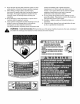
Operator's Manual SERIES 1500 Hydrostatic Lawn Tractor Model SLT1554 IMPORTANT: READ SAFETY RULES AND INSTRUCTIONS CAREFULLY Warning: This unit is equipped with an internal combustion engine and should not be used on or near any unimproved forest-covered, brush-covered or grass-covered land unless the engine's exhaust system is equipped with a spark arrester meeting applicable local or state laws (if any).
TABLEOFCONTENTS Content Page 3 Important Safe Operation Practices Slope Gauge Tractor Set-up Know Your Lawn Tractor Operating Your Lawn Tractor Making Adjustments Maintaining Your Lawn Tractor Content Service Page 25 7 8 Off-season Storage Maintenance Chart 29 29 9 12 Troubleshooting Attachments & Accessories 30 31 17 19 Specifications Warranty Information 32 34 FINDINGMODELNUMBER This Operator's Manual is an important part of your new lawn tractor.
SECTION1: IMPORTANT SAFEOPERATION PRACTICES WARNING: This symbol points out important safety instructions which, if not followed, could endanger the personal safety and/or property of yourself and others. Read and follow all instructions in this manual before attempting to operate this machine. Failure to comply with these instructions may result in personal injury. When you see this symbol--heed its warning.
23. Mufflerandenginebecomehotandcancausea burn.Donottouch. 24. Checkoverhead clearances carefullybeforedriving underlowhangingtreebranches, wires,door openingsetc.,wheretheoperatormaybestruckor pulledfromtheunit,whichcouldresultinserious injury. 25. Disengage allattachment clutches,depressthe brakepedalcompletely andshiftintoneutralbefore attempting to startengine. 26. Yourmachineis designedtocutnormalresidential grassofa heightnomorethan10".Donotattempt tomowthroughunusuallytall,drygrass(e.g.
e. Useextremecarewhenapproaching blind corners,doorways, shrubs,treesor other objectsthatmayblockyourvisionofachild whomayrunintothemachine. f. Toavoidback-overaccidents,always e. f. g. disengage the cutting blade(s) before shifting into reverse, The "Reverse Caution Mode" should not be used when children or others are around, g. h. Keep children away from hot or running engines. They can suffer burns from a hot muffler. allow space for fuel expansion. Replace gasoline cap and tighten securely.
8. Nevertamperwiththesafetyinterlocksystemorother safetydevices.Checktheirproperoperationregularly. 9. Afterstrikinga foreignobject,stoptheengine, disconnect thesparkplugwire(s)andgroundagainst theengine.Thoroughly inspectthemachineforany damage.Repairthedamagebeforestartingand operating. 10. Neverattempttomakeadjustments or repairstothe machinewhiletheengineisrunning. 11. Grasscatchercomponents andthedischarge coverare subjecttowearanddamagewhichcouldexpose movingpartsorallowobjectstobethrown.
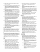
Sight and hold this Ueven with a verticantree... or a corner of a building,., m_ or a fence post i | | | ILl _L ..,.I &i Z I-I,l.I a 15° p..
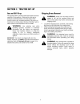
SECTION3: TRACTOR SET-UP GasandOilFill-up The gasoline tank is located under the fender and has a capacity of three gallons. Unthread the fuel cap by turning it counterclockwise. Use only clean, fresh (under 30 days old), unleaded gasoline. Fill tank to no more than four inches below the top of the filler neck to allow space for fuel expansion. Do not overfill. ,_ handling gasoline. extremely WARNING: Use Gasoline extreme iscare when flammable and the vapors are explosive.
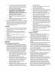
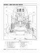
SECTION4: KNOWYOURLAWNTRACTOR A B C H NOTE: Steering Wheel not shown for clarity.
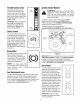
ThrottleControlLever The throttle control lever is located on the left side of the IgnitionSwitch Module Fast Position WARNING: Never leave a running machine unattended. Always disengage PTO, move shift lever into neutral position, set parking brake, stop engine and remove key to prevent unintended starting. tractor's dash panel. This lever controls the speed of the engine. When set in a given position, the throttle will maintain a uniform engine speed.
HourMeter ElectricPTO/ BladeEngageKnob Located in the center of the tractor's console, the hour meter operates whenever the ignition key is rotated out of the STOP position and records the actual hours of tractor operation. See Figure 3. To engage the power to the cutting deck or other (separately available) attachments, pull outward on the PTO/Blade Engage knob. Push the PTO/ Blade Engage knob inward to disengage the power to the cutting deck. 234.
SECTION5: OPERATING YOURLAWNTRACTOR WARNING: WARNING AVOIDSERIOUS INJURYORDEATH • • • • • • • • • • • • GO UP AND DOWN SLOPES, NOT ACROSS. AVOID SUDDEN TURNS. DO NOT OPERATE THE UNIT WHERE IT COULD SLIP OR TIR IF MACHINE STOPS GOING UPHILL, STOP BLADE(S) AND BACK DOWNHILL SLOWLY. DO NOT MOW WHEN CHILDREN OR OTHERS ARE AROUND. NEVER CARRY CHILDREN, EVEN WITH BLADES OFR LOOK DOWN AND BEHIND BEFORE AND WHILE BACKING. KEEP SAFETY DEVICES (GUARDS, SHIELDS, AND SWITCHES) IN PLACE AND WORKING.
• If the gauge wheels have excessive clearance with the surface below, lower the wheels to the index hole that provides the approximate 1/2" clearance as described above. Refer to Levelingthe Deckon page 17 of this manual for more detailed instructions regarding various deck adjustments. SettingtheGaugeWheels Select the height position of the cutting deck by placing the deck lift lever in any of the six different cutting height notches on the right fender.
• EngagingtheParking Brake To engage the parking brake: • Fully depress the brake pedal and hold it there while gently pushing the parking brake lever downward. IMPORTANT: Do NOT attempt to change the direction of travel when the tractor is in motion. Always bring the tractor to a complete stop before pivoting the drive pedal from forward to reverse or vice versa. • Hold the parking brake lever down while removing your foot from the brake pedal.
• • Depress the brake pedal to disengage the cruise control and stop the tractor. Lightly depress the drive pedal. IMPORTANT: Never attempt to move the tractor manually without first opening the hydrostatic relief valve. Doing so will result in serious damage to the tractor's transmission. To change the direction of travel to reverse when operating with cruise control, depress the brake pedal to disengage the cruise control and bring the tractor to a complete stop.
• • • • For best results it is recommended that the first two laps be cut with the discharge thrown towards the center. After the first two laps, reverse the direction to throw the discharge to the outside for the balance of cutting. This will give a better appearance to the lawn. Do not cut the grass too short. Short grass invites weed growth and yellows quickly in dry weather. Mowing should always be done with the engine at full throttle.
SECTION6: MAKINGADJUSTMENTS • Locate the two lock nuts on the opposite side of the stabilizer bracket. See Figure 9. Tighten the lock nuts to raise the front of the deck; loosen the lock nuts to lower the front of the deck. • Retighten the two jam nuts loosened earlier when proper adjustment is achieved. adjustments engineto ismake running, WARNING: while Nevertheattempt any except where specified in the operator's manual.
ParkingBrakeAdjustment HexNut and LockWasher WARNING: Never attempt to adjust the brakes while the engine is running. Always disengage PTO, stop engine and remove key to prevent unintended starting. J PivotBar If the tractor does not come to a complete stop when the brake pedal is completely depressed, or if the tractor's rear wheels can roll with the parking brake applied, the brake is in need of adjustment. The brake disc can be found on the right side of the transmission in the rear of the tractor.
SECTION7: MAINTAININGYOURLAWNTRACTOR NOTE: Refer to MaintenanceCharton page 29 for a reference of recommended maintenance intervals. RECOMMENDED SAE ViSCOSiTY GRADES WARNING: Before performing any maintenance or repairs, disengage PTO, set parking brake, stop engine and remove key to prevent unintended starting.
Remove the oil fill cap/dipstick from the oil fill tube and SLOWLY pour oil into the oil fill tube. Do NOT pour more than 6 oz. of oil at a time without first stopping and re-checking the oil level. Fill the crankcase until the oil level reaches the full Push the oil drain valve in slightly, then rotate counterclockwise and pull outward to begin draining oil. (F) mark on the dipstick. Refer to Figure 13.
• Re-fillingthe Crankcase with Oil IMPORTANT:The engine (with oil filter) has a capacity of 2.0 liters (67.60 oz.) Do NOT overfill. Always check the level on the dipstick as instructed on page 19 before adding more oil. • • NOTE: For the proper oil type, refer to the chart on page 19 of this manual. • • • • Clean the area around the oil fill tube to prevent debris from entering the crankcase. Slowly pour oil into the fill tube.
Visually inspect the filter periodically for a build-up of residue inside the filter body, and for a dirty element which can be indicated by discoloration. Replace the fuel filter when dirty. Spark Plug(s) Every 200 hours of operation, remove the spark plug(s), check condition, and reset the gap or replace with a new plug(s) as necessary. • • • • • Lift the tractor's hood and locate the spark plug wire on the front, right area of the engine. Carefully pull the spark plug wire boot off of the spark plug.
7. Move the tractor's PTO (Blade Engage) into the ON position. 8. Remain in the operator's position with the cutting deck engaged for a minimum of two minutes, allowing the underside of the cutting deck to thoroughly rinse. 9. Move the tractor's PTO (Blade Engage) into the OFF position. 10. Turn the ignition key to the STOP position to turn the tractor's engine off. 11. Turn the water off and detach the hose coupler from the water port on your decks surface. 12.
• • • • • • Make sure the fuel tank is filled with clean, fresh gasoline. Make sure the fuel tank cap vent is not blocked and that it is operating properly. If the fuel tank is equipped with a shut-off valve, make sure it is open. Make sure that the in-line fuel filter is clean and unobstructed. Replace the filter if necessary. Make sure fuel is reaching the carburetor. Check the fuel lines and fuel pump for restrictions or faulty components, replace as necessary.
SECTION8: SERVICE Tires Place a block of wood between the center deck housing baffle and the cutting blade to act as a stabilizer. See Figure 20. inflation pressureNever shownexceed on the the sidewall of the WARNING: maximum tire. ,_ HexFlangeNut The recommended operating tire pressure is approximately 10 psi for the rear tires and 14 psi for the front tires. Refer to the tire sidewall for exact tire manufacturer's recommended or maximum psi. Do not overinflate.
Battery CuttingDeckRemoval The battery is sealed and is maintenance-free. Acid levels cannot be checked and fluid can not be added. To remove the cutting deck, proceed as follows: • Place the PTO/Blade Engage knob in the disengaged (OFF) position and engage the parking brake. • Lower the deck by moving the deck lift lever into the bottom notch on the right fender. • Remove the deck belt from around the tractor's electric PTO clutch (refer to Changing the BeckBelt).
Hydrostatic Transmission Changingthe DeckBelt Keep the area around the transmission cooling fan free of grass and debris at all times. The hydrostatic transmission is sealed at the factory and is maintenance free. The fluid level cannot be checked and on most models, cannot be changed. ,_ If your tractor is equipped with a transmission drain plug (see Figure 22), exposed to extreme conditions (hilly terrain, towing, etc.
• With belt tension relieved, carefully remove the belt from around the left-hand spindle pulley. NOTE: The idler pulley(s) may have to be loosened, but not removed, in order to remove the belt from around them. IMPORTANT: Carefully allow the ratchet to pivot rearward before removing it from the square hole. • • • Remove the deck belt from around all pulleys, including the deck idler pulley(s) and the electric PTO clutch. Route the new belt as shown in Figure 24.
SECTION9: OFF-SEASON STORAGE Clean and lubricate the tractor as instructed in Section7: MAINTAINING YOURLAWNTRACTORon page 19 of this manual before storing for an extended period. To empty the system, run the engine until the tank and system are empty. WARNING: Drain fuel only into an approved container outdoors, away from an open flame. Allow engine to cool. Extinguish cigarettes, cigars, pipes, and other sources of ignition prior to draining fuel.
SECTION11: TROUBLESHOOTING Trouble Possible Engine fails to start PTO/Blade Engage knob engaged. Parking brake not engaged. Spark plug wire(s) disconnected. Throttle control lever not in correct starting position. Choke not activated Fuel tank empty, or stale fuel. Blocked fuel line. Faulty spark plug. Engine flooded. Unit running with CHOKE activated. Spark plug wire(s) loose. Blocked fuel line or stale fuel. Engine runs erratic Corrective Cause(s) Vent in gas cap plugged.
SECTION12: ATTACHMENTS & ACCESSORIES The following attachments and accessories are compatible for Series 1500 Lawn Tractors. See your Cub Cadet dealer or the retailer from which you purchased your tractor for information regarding price and availability.
SECTION13: SPECIFICATIONS Capacities Fuel Tank 15.1 liters (4.0 gallons) Engine Crankcase (w/filter) 2.0 liters (67.6 oz.) Transmission 2.25 liters (76 oz.) Hydrostatic Transmission Make and Model Hydro-Gear0510 Gear Ratio 22.2:1 Forward Speed 0m.p.h.-5.2m.p.h. Reverse Speed 0m.p.h.-2.3m.p.h. Engine (Air-cooled, 4-cycle) Make Kohler Command Model CV740 Cylinders Twin Bore 83 mm (3.27 in.) Stroke 67 mm (2.64 in.) Displacement 725 cc (44.2 cubic in.) Power @3600 RPM 20.
NOTES 33
FEDERAL KOHLER CO. AND CALIFORNIA EMISSION CONTROL SYSTEMS LIMITED WARRANTY UTILITY AND LAWN AND GARDEN ENGINES The U.S. Environmental Protection Agency (EPA), the California Air Resources Board (CARB), and Kohler Co. are pleased to explain the Federal and California Emission Control Systems Warranty on your small off-road equipment engine. For California, engines produced in 1995 and later must be designed, built and equipped to meet the state's stringent anti-smog standards.
MANUFACTURER'S CUB CADET LLC ONE YEAR LIMITED WARRANTY (COMMERCIAL USE) The limited warranty set forth below is given by CUB CADET b. LLC ("CUB CADET") with respect to new merchandise purchased and used in the United States, its possessions and territories. blade adapters, grass bags, rider deck wheels, seats, snow thrower skid shoes, shave plates and tires.
CUB CADET LLC MANUFACTURER'S LIMITED WARRANTY (RESIDENTIAL The limited warranty set forth below is given by CUB CADET LLC ("CUB CADET") with respect to new merchandise purchased and used in the United States, its possessions and territories.