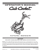
Safety • Assembly • Operation • Tips & Techniques • Maintenance • Troubleshooting • Parts Lists • Warranty OPERATOR’S MANUAL Front Tine Tiller — Model Series 390 IMPORTANT READ SAFETY RULES AND INSTRUCTIONS CAREFULLY BEFORE OPERATION Warning: This unit is equipped with an internal combustion engine and should not be used on or near any unimproved forest-covered, brushcovered or grass-covered land unless the engine’s exhaust system is equipped with a spark arrester meeting applicable local or state laws (i
This Operator’s Manual is an important part of your new tiller. It will help you assemble, prepare and maintain the unit for best performance. Please read and understand what it says. Table of Contents Safety Labels....................................................... 3 Safe Operation Practices.................................... 4 Assembly.............................................................. 6 Operating Your Tiller............................................ 8 Maintaining Your Tiller..........
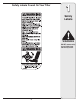
Safety Labels Found On Your Tiller 1 Safety Labels WARNING DO NOT remove safety (or any) labels from tiller for any reason.
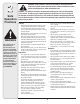
2 Safe Operation Practices WARNING: Engine Exhaust, some of its constituents, and certain vehicle components contain or emit chemicals known to State of California to cause cancer and birth defects or other reproductive harm. DANGER: This machine was built to be operated according to the rules for safe operation in this manual. As with any type of power equipment, carelessness or error on the part of the operator can result in serious injury.
• • • • • • • • • • • After striking a foreign object, stop the engine, disconnect the spark plug wire and ground against the engine Thoroughly inspect the machine for any damage. Repair the damage before starting and operating. Disengage all clutch levers (if fitted) and stop engine before you leave the operating position (behind the handles). Wait until the tines come to a complete stop before unclogging the tines, making any adjustments, or inspections.
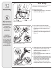
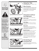
3 Tiller Setup References to right and left side of tiller are determined from behind the unit in the operating position. Assembly NOTE: Stand behind the tiller as if you were going to operate it. Your right hand corresponds to right side of tiller; your left hand corresponds to left side of tiller. IMPORTANT This unit is shipped without gasoline or oil in the engine. Fill up gasoline and oil as instructed in the accompanying engine manual BEFORE operating your tiller. Handle Attachment 1.
. Locate the carriage bolt, bell washer and hand knob packed with your unit. 8. Insert the carriage bolt through the welded bracket on the handle, bell washer, handle brace and into the hand knob. See Figure 3–4. 9. Select one of the three handle height positions (three notches in welded handle bracket) and tighten the hand knob to secure the handle in the desired position. Figure 3–4. Return to lower handle and tighten the hex bolt securely 3 Assembly Figure 3–4: Remove hardware from lower handle.
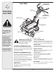
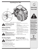
4 Your Tiller Reverse Tine Engagement Lever Handle Operating Your Tiller Forward Tine Engagement Lever Throttle Control Handle Knob Depth Stake WARNING The tine clutch control is a safety device. Never attempt to bypass its operation. Use extreme care when handling gasoline. Gasoline is extremely flammable and the vapors are explosive. Never fuel tiller indoors or while engine is hot or running. Extinguish cigarettes, cigars, pipes, and other sources of ignition.
Operating Your Tiller 4 Operating Your Tiller Choke Throttle WARNING Figure 4–2: Engine choke and throttle controls WARNING: Read, understand, and follow all instructions and warnings posted on the machine and in this manual before operating. Before Starting Gas And Oil Fill-Up Service the engine with gasoline and oil as instructed in the separate engine manual packed with your tiller. Read instructions carefully. 3. Move throttle control 1/3 of the way toward the FAST position. 4.
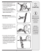
4 Using Your Tiller Your tiller is designed for seed bed preparation, cultivating, furrowing, and mulching. Wheel Position The tiller is shipped with the wheels adjusted so that the unit sits level. The wheels need to be adjusted to meet your tilling needs before operation. This adjustment is made by removing the clevis pin from the wheel yoke and raising the wheels to the desired height. See Figure 4–3. Operating Your Tiller Figure 4–3: Wheel and depth stake positioning.
Tilling Procedure When tilling, leave approximately eight inches of untilled soil between the first and second tilling paths, then make the third path between the first and second, Figure 4–7. In some soils, the desired depth is obtained the first time over the garden. In other soils, the desired depth is obtained by going over the garden two or three times. Passes should be made across the length and width of the garden alternately. Rocks which are turned up should be removed from the garden area.
5 Maintaining Your Tiller Lubrication WARNING: Disconnect the spark plug wire and ground it against the engine before performing any repairs. Pivot Points Remove the belt cover and lubricate all pivot points and linkages at least once a season with light oil. Keep belts free of lubrication. Engine Refer to the separate engine manual for engine maintenance instructions. Tine Shafts Maintain engine oil as instructed in the separate engine manual packed with your unit.
5 Belt Replacement Forward Drive Belt 1. Remove reverse drive belt as instructed in the previous section. 2. Remove the return spring. See Figure 5–3. Maintaining Your Tiller 3. Remove idler pulley bolt and move belt from under idler pulley keeper. See Figure 5–4. 4. The forward idler belt will not clear the belt keepers near the engine pulley. You must remove the reverse idler bracket to allow the belt to move off of the engine pulley.
5 Maintaining Your Tiller Cable Adjustment From time to time you may need to adjust the tension on the forward and reverse tine engagement cables. 1. Disconnect and ground the spark plug wire against the engine. Reverse Tine Engagement Cable 2. Adjust either the forward or reverse clutch cable by loosening the hex nut. See Figure 5–8. 3. Turn the cable collar section one or two turns to add or lesson tension on the cable. See Figure 5–9.
Off-Season Storage If the tiller will not be used for a period longer than 30 days, the following steps should be taken to prepare the tiller for storage. 1. Clean the exterior of engine and the entire tiller thoroughly. Lubricate the tiller as described in the lubrication instructions. 3. Refer to the engine manual for correct engine storage instructions. 4. Wipe tines with oiled rag to prevent rust. 5. Store tiller in a clean, dry area. Do not store next to corrosive materials, such as fertilizer.
10 6 9 4 1 11 2 12 13 5 3 7 2 8 14 50 16 15 54 55 19 22 49 21 29 30 20 28 27 26 31 32 35 23 36 37 38 42 56 37 34 25 33 30 40 24 39 41 56 30 23 43 46 27 47 48 16
9 Ref. Part No. Part Description Ref. Part No. Part Description 1 712-0442 Acorn Lock Nut 1/4-20 28 710-0805 Hex Bolt 5/16-18 x 1.5” Lg. 2 736-3020 Flat Washer.271” I.D. x.630” O.D. 29 710-0189 Hex Bolt 5/16-18 x 3” Lg. 3 720-0270A Reverse Handle Grip 30 736-0242 Wash. Bell.340” I.D. x.872” O.D. 4 731-1600 31 711-1036A Spec. Hex Nut 5 710-0779A Truss Mach. Scr. #10 x 1/2” Lg. 32 736-0119 L-Wash. 5/16” I.D. 6 720-0274 Handle Grip 33 710-3008 Hex Bolt 5/16-18 Gr.
26 25 24 24 23 48 13 30 29 31 3 49 27 32 34 28 35 36 10 42 33 6 10 †††Honda Engine 45 14 38 50 5 53 22 7 9 52 10 54 51 8 44 6 43 7 11 4 46 47 5 1 19 16 2 20 3 21 17 18 18
Ref. Part No. Part Description Ref. Part No. Part Description 1 712-0392 Hex L-Stop nut 1/4-28 26 748-0350 Pulley Mounting Adapter 2 736-3020 Flat Wash.266” I.D. x.625” O.D. 27 736-0112 Bell-Wash.525” I.D. x 1.5” O.D. 3 710-0599 Hex Washer TT-Tap Scr. 1/4-20 x.5” 28 712-3029 Hex Jam Nut 1/2-20 Thd. 4 711-0920 Belt Cover Bolt 29 732-0697 Return Spring 5 712-04063 Hex Flange Top L-Nut 5/16-18 30 786-0040B Reverse Bracket 6 710-0723 Hex Hd. Scr. 3/8-16 x 1.25” Lg.
MANUFACTURER’S LIMITED WARRANTY FOR The limited warranty set forth below is given by Cub Cadet LLC with respect to new merchandise purchased and used in the United States, its possessions and territories. “Cub Cadet” warrants this product against defects in material and workmanship for a period of two (2) years commencing on the date of original purchase and will, at its option, repair or replace, free of charge, any part found to be defective in materials or workmanship.