INTRODUCTION Welcome to the World of Cub Cadet Yanmar Tractor Thank you for purchasing our tractor product that has been designed and manufactured based on our state-of-the-art technology and rich expertise in developing and manufacturing tractor products. Handle your tractor correctly by following the instructions contained in this Operator’s Manual so that it provides you long years of reliable and faithful service. This manual constitutes an indispensable part of your Cub Cadet Yanmar tractor product.
TABLE OF CONTENTS 1. SAFETY PRECAUTIONS ................................................................................... 1-1 1. About This Manual .................................................................................................................. 1-1 2. Safety-Alert Symbols............................................................................................................... 1-2 3. Precautions before Operating Your Tractor ............................................................
TABLE OF CONTENTS 8. OPERATING THE TRACTOR............................................................................. 8-1 1. Operating a New Tractor ......................................................................................................... 8-2 2. Operation of the Tractor .......................................................................................................... 8-3 Turn Signals ................................................................................................
TABLE OF CONTENTS 12.TIRES, WHEELS AND BALLAST .................................................................... 12-1 1. Tires ...................................................................................................................................... 12-1 Inflation Pressure.................................................................................................................................................12-2 Wheel Bolt Tightening Torque ........................................
TABLE OF CONTENTS 6. Every 200 Hours.................................................................................................................. 14-27 Replacing the Engine Oil Filter ..........................................................................................................................14-27 Adjusting the Toe-in...........................................................................................................................................14-28 7. Every 300 Hours.......
TABLE OF CONTENTS 16.STORAGE......................................................................................................... 16-1 1. Safe Practices for Storage .................................................................................................... 16-1 Fuel......................................................................................................................................................................16-2 Engine ..................................................
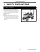
1. SAFETY PRECAUTIONS 1. SAFETY PRECAUTIONS 1. About This Manual This Operator’s Manual presents you messages that help you remain aware of potential hazards and possible machine damage in operating and servicing your machine. Carefully study all the information in it so that you can positively avoid personal injury and damaged properties.
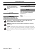
1. SAFETY PRECAUTIONS 2. Safety-Alert Symbols The safety-alert symbols appear with most safety statements. It means attention, become alert, your safety is involved! Please read and strictly observe the message that follows the safety-alert symbols. CAUTION Indicates a hazardous situation which, if not avoided, could result in minor or moderate injury. NOTICE Indicates a situation which can cause damage to the machine, personal property and/or the environment or cause the equipment to operate improperly.
1. SAFETY PRECAUTIONS 3. Precautions before Operating Your Tractor 5. Check overhead clearance carefully before driving under power lines, wires, bridges or low hanging tree branches, before entering or leaving building, or in any other situation where the operator and/or Roll-Over Protective Structure (ROPS) may be struck, which could result in serious injury. 6. Make sure that any person (other than a usual operator) who will operate the tractor studies this Operator’s Manual before operation.
1. SAFETY PRECAUTIONS 15. Only use the implements that satisfy the requirements in this manual or are approved by your Cub Cadet Yanmar dealer. (See “4. IMPLEMENT CAPACITIES”) 16. When using front or rear mounted implements, install an appropriate weight(s) to the front or rear of your tractor to prevent upsetting of the tractor. If you choose to use the front loader, mount an implement or ballast to the 3-point hitch in order to get the tractor to stabilize.
1. SAFETY PRECAUTIONS 2. Working with Your Tractor 3. Considerations for Safety of Children 1. Make sure that all the covers and guards are in correct position. Replace any missing or damaged cover immediately. 2. Before turning or when traveling on a rough terrain, or before stopping, decrease the tractor speed in order to prevent upsetting. 3. Use extra caution when operating over rough ground, when crossing ditches or slopes, and when turning corners. 4.
1. SAFETY PRECAUTIONS 5. Operating Your Tractor on Slopes DO NOT: On a slope, the tractor is less stable and more prone to tip-over, possibly leading to serious injury or death. Remain very cautious when your tractor is on any slope. ●Do not mow near drop-offs, ditches or embankments. The mower could suddenly turn over if a wheel goes over the edge of a cliff or ditch, or if an edge caves in. WARNING ●Before approaching a slope, select an appropriate speed setting.
1. SAFETY PRECAUTIONS 6. Traveling on a Road 7. Always travel at a speed that allows you to maintain control of the tractor. 8. Avoid engaging differential lock while traveling on a road. It may cause the operator to lose control of the tractor. 9. While traveling on a road, do not suddenly turn the steering wheel. Such an action can lead to loss in the stability of the tractor, and can cause an extremely dangerous situation. 10. While on a road, do not attempt to operate an implement.
1. SAFETY PRECAUTIONS 8. Operating the Power Take Off (PTO) 3. Before installing or operating Power Take Off (PTO)-driven implement, carefully study the manufacturer’s Operator’s Manual and the safety decals on the implement. 4. When installing the Power Take Off (PTO)- driven implements, engage the parking brake securely and chock the four wheels. Do not approach or access any rotating component. 1.
1. SAFETY PRECAUTIONS 11. Safe Practices for Servicing Your Tractor 9. Prior to “jump starting” a tractor that has a fully depleted battery, read and follow all the instructions in the “7. OPERATING THE ENGINE”. 10. Carefully loosen the radiator cap to the first stop, and allow excessive pressure to escape, and only then remove the radiator cap. If the tractor is equipped with a coolant reserve tank, add coolant or water to the reserve tank, not to the radiator (See “Checking the Cooling System”).
1. SAFETY PRECAUTIONS 19. Do not change the engine governor settings or overspeed the engine. Excessive engine speeds are dangerous. 20. Observe proper disposal laws and regulations. Prior to disposal, determine the proper method to dispose of waste from your local Environmental Protection Agency. Recycling centers are established to properly dispose of materials in an environmentally safe fashion. 21. Use proper containers when draining fluids.
1. SAFETY PRECAUTIONS 12. Understanding the Tractor Safety Decals ■ Safety-Alert Symbols The tractor safety decals illustrated in this section are provided in critical areas on the tractor so that people including the operator can remain always aware of potential hazards. The tractor safety decals contain the words DANGER, WARNING and CAUTION together with the safety-alert symbols. DANGER and WARNING stand for the most serious hazards.
1. SAFETY PRECAUTIONS (A) CY1A8160-65300 DANGER TO AVOID INJURY OR DEATH: ●Do not start engine by shorting across starter terminals or bypassing safety start switch. ●Start engine only from seat with transmission and PTO OFF. (A) P3014902 DANGER TO AVOID INJURY OR DEATH: Do not start engine by 䇭shorting across starter 䇭terminals or bypassing 䇭safety start switch. Start engine only from 䇭seat with transmission 䇭and PTO OFF.
1. SAFETY PRECAUTIONS (C) CY124764-44810 (C) CAUTION 1. Adding of water is done through the sub-tank. 2. Before starting, make sure that water level is up to the "Full" mark. 3. If water level is low, remove the cap of the subtank and add water until the "Full" mark is reached. P3014947 (D) CY1A8160-51520 (D) DANGER/POISON (ENGLISH) ●SHIELD EYES: EXPLOSIVE GASES CAN CAUSE BLINDNESS OR INJURY. ●NO SPARKS, FLAMES, SMOKING. ●SULFURIC ACID CAN CAUSE BLINDNESS OR SEVERE BURNS.
1. SAFETY PRECAUTIONS (E) CY1A7880-65600 (E) WARNING READ OPERATOR'S MANUAL 1. Do not operate the machine without guards shields and safety devices in place and working. 2. Keep all riders off tractor during operation. 3. Make certain everyone is clear of machine before starting engine or operation. 4. Keep hands, feet and clothing away from powerdriven parts. 5. Use seat belt. 6. Reduce speed when turning or operating around hazards, on rough ground or steep slopes. 7.
1. SAFETY PRECAUTIONS (G) CY1A7880-65350 (G) WARNING Only use PTO in reverse when there are no children or others around P3014940 WARNING Only use PTO in reverse when there are no children or others around (H) CY1A7880-85170 (H) WARNING This structure's protective capability may be impaired by structural damage, overturn, or alteration. If any of these conditions occur, this structure must be replaced.
1. SAFETY PRECAUTIONS (J) CY198220-65621 WARNING AVOID INJURY FROM PTO ●Keep all shields in place ●Keep hands, feet and clothing away ●Operate only with 540 RPM (J) P3014938 WARNING AVOID INJURY FROM PTO Keep all shields in place Keep hands,feet and clothing away Operate only with 540 RPM (K) CY1A8160-65310 WARNING TO AVOID INJURY: Before leaving or servicing machine, ●Stop engine. ●Set parking brake. ●Park on level ground. ●Lower all implements to the ground. ●Remove key.
2. SERVICING THE TRACTOR 2. SERVICING THE TRACTOR Your Cub Cadet Yanmar dealer wants to remain committed to the tractors our customers have purchased and intends to support our customers in fully developing the performance of their Cub Cadet Yanmar tractors. After carefully studying this manual, the customers themselves will be able to do a certain portion of the regular maintenance work.
3. SPECIFICATIONS 3. SPECIFICATIONS 1. Specifications Table Model Sc2400 Power Take Off (PTO) Power hp (kW) Maker YANMAR Model 3TNV72 Type Indirect Injection, Vertical, Water-Cooled, 4 Cycle Diesel Number of Cylinders 3 Bore and Stroke in. (mm) 2.834 × 2.913 (72 × 74) cu. in. (L) 55.1 (0.903) Gross Power hp (kW) 24.0 (17.9) Net Power hp (kW) 20.4 (15.
3. SPECIFICATIONS Ag (R1) Tire Turf (R3) Industrial (R4) Front 18 × 8.50-10 Rear 26 × 12.00-12 Front 18 × 8.50-10 Rear 26 × 12.00-12 Front 18 × 8.50-10 Rear 26 × 12.00-12 Clutch Traveling System – Steering Power Steering Hydrostatic Transmission, 2 Range Speeds Transmission Drive Selected 4WD Brake Wet plates Minimum Turning Radius ft (m) Differential Lock 7.2 (2.
4. IMPLEMENT CAPACITIES 4. IMPLEMENT CAPACITIES The Cub Cadet Yanmar tractor has been carefully tested in the configuration equipped with implements sold or approved by Cub Cadet Yanmar and has proved to perform properly. Do not use any implement that has not been sold or recommended by a Cub Cadet Yanmar dealer, or that fails to satisfy the specified values given below. Never mount an implement that is not approved for the Cub Cadet Yanmar tractor.
5. NAMES AND FUNCTIONS OF COMPONENTS 5. NAMES AND FUNCTIONS OF COMPONENTS 1.
5. NAMES AND FUNCTIONS OF COMPONENTS 2.
5. NAMES AND FUNCTIONS OF COMPONENTS 3. Instrument Panel, Switches and Hand Controls (1) (7) (6) (5) (4) 3014905 (3) (2) (6) Preheater Pilot Light This light illuminates when the engine starter key switch is turned to the preheating position. Preheating time should be determined according to outside air temperature. For details, refer to the table below. (1) Tachometer This meter indicates the current engine speed in increments of 100 rpm.
5. NAMES AND FUNCTIONS OF COMPONENTS (8) (9) 3014903 (8) Headlight / Work Light / Turn Signal Switch Use the blue lever to turn ON/OFF the headlights and work lights. Turning the blue lever to the (b) position illuminates the headlights and turning it to the (c) position illuminates the work lights and headlights at the same time. The yellow lever is a turn signal switch. Move the turn signal switch right to signal a right turn. Move the turn signal switch left to signal a left turn.
6. PRE-OPERATION CHECK 6. PRE-OPERATION CHECK 1. Pre-Operation Check ●Check the tractor for damage, excessive wear, cracks, missing parts, exposed wiring and any other problems, including leaks. ●Check the joints and connections for looseness. ●Check that all the lights illuminate. ●Check that all the safety-alert decals are in correct position. If any problem is detected, contact your local Cub Cadet Yanmar dealer, and correct the problem. NEVER operate the tractor when a problem has been indicated. 2.
7. OPERATING THE ENGINE 7. OPERATING THE ENGINE DANGER WARNING ALWAYS remain seated in the operator’s station when starting the engine or actuating the levers or controls. NEVER run or idle the engine in a confined area that is poorly ventilated or not ventilated at all. The engine emits carbon monoxide as that is colorless, odorless and can cause death.
7. OPERATING THE ENGINE 2. Sit on the seat. ■ Adjusting the Operator's Seat 1. Engage the parking brake securely and stop the engine. 2. Sit on the seat. 3. Pull the seat adjustment lever to the left. 4. Move the seat forward and backward to find the optimal position and then release the seat adjustment lever. 5. While remaining seated, confirm that various control levers can be comfortably operated. If any control lever cannot be operated comfortably, readjust the seat position as necessary.
7. OPERATING THE ENGINE 3. Remove foot from the forward and reverse drive pedal and set the pedal to the NEUTRAL position. NOTE: ●With the parking brake engaged, the forward and reverse drive pedal is locked in the NEUTRAL position. 4. Engage the parking brake securely. ■ Engaging the Parking Brake (A) (B) 1. Fully depress the brake pedal. 2. Fully pull the parking brake lever backward to engage the parking brake securely. 3. Remove foot and make sure that the brake is fully locked.
7. OPERATING THE ENGINE 6. Turn off the Power Take Off (PTO) switch. (A) Push in and set the Power Take Off (PTO) switch to the OFF position. (A) Power Take Off (PTO) switch (a) OFF position (b) ON position 3014919g (a) (b) 3014926 7. Fully push the 3-point hitch control / cutting height adjustment lever forward to the lowest position and lower the mid- or rear-mounted implements to the ground.
7. OPERATING THE ENGINE 9. Set the throttle control lever about halfway. (A) Throttle control lever (a) To increase the engine speed, pull the throttle control lever backward. (b) To decrease the engine speed, push the throttle control lever forward. (b) (A) (a) 3014903e 10.Insert the key into the starter key hole and turn the key to the ON position. (A) (B) (A) OFF position: The engine must not run.
7. OPERATING THE ENGINE ■ Checking the Lights on the Instrument Panel When the key is turned to the ON position: 1. The engine oil pressure warning light turns ON. 2. The alternator / battery charging light turns ON. (A) Engine oil pressure warning light (B) Alternator / Battery charging light NOTE: (A) ●The engine oil pressure warning light turns off within 5 seconds after the engine is started. ●The alternator / battery charging light turns off within 10 seconds after the engine is started.
7. OPERATING THE ENGINE NOTE: ●While turning the key to the preheating position, the preheater pilot light turns ON. Also, the engine oil pressure warning light and the alternator / battery charging light turn ON. (A) (A) Preheater pilot light 3014905 12.Turn and hold the key to the START position. After the engine is successfully started, release the key. IMPORTANT: Avoid starter damage. ●Do not hold the key in the START position for more than 15 seconds at a time.
7. OPERATING THE ENGINE 2. Stopping the Engine 1. Remove foot from the forward and reverse drive pedal. 2. After the tractor has completely stopped, turn off the Power Take Off (PTO) switch, lower the implement (if installed) to the ground and then engage the parking brake securely. 3. Run the engine at a lowest possible speed for at least 2 minutes. (B) (A) 3013703a 4. Turn the key to the OFF position. 5. Remove the key from the starter key switch. 6.
7. OPERATING THE ENGINE 3. Restarting a Stalled Engine IMPORTANT: Avoid engine damage. ●If the engine stalls while operating under load, immediately restart the engine to prevent overheating of the engine. 1. Engage the parking brake securely. 2. Set the range shift lever to the slow position. (A) (A) Range shift lever (a) Slow position (a) 3014919a 3. Turn off the Power Take Off (PTO) switch. CAUTION (a) ●To prevent a possible accident, fully lower all the implements to the ground.
8. OPERATING THE TRACTOR 8. OPERATING THE TRACTOR WARNING Accident Hazard ALWAYS decrease tractor speed before turning, when traveling on a rough terrain or before stopping to prevent roll-over. ALWAYS remain alert to behaviors of children when operating the tractor because they are usually very curious about moving machines. Do not attempt to turn with the differential lock engaged. Attempting to turn the tractor while the differential lock is engaged can lead to a roll-over.
8. OPERATING THE TRACTOR 1. Operating a New Tractor The service life of the tractor is governed by how adequately it is handled and maintained. Of course, any newly manufactured tractor has been tested; however, various parts must be broken in. Therefore, operate the tractor at low speeds for the first 50 operating hours, and avoid heavy work or operation before the various parts have been sufficiently run.
8. OPERATING THE TRACTOR 2. Operation of the Tractor CAUTION Avoid injury: ●Before starting or operating the tractor, always check the area around the tractor for obstacles and any person nearby. Turn off the Power Take Off (PTO) switch and raise the implement. IMPORTANT: Avoid damage. ●To prevent damage to the transmission, stop the tractor completely before shifting the range shift lever. 1. Sit on the seat.
8. OPERATING THE TRACTOR 3. Start the engine. Start the engine by referring to “7. OPERATING THE ENGINE”. 4. Select travel speed. ■ Range Shift Lever Use the range shift lever to select the speed that best suits the intended operation. (A) Range shift lever (a) SLOW : Used for heavy-load operation. Low traveling speed. (b) FAST : Used for light-load operation. High traveling speed.
8. OPERATING THE TRACTOR 5. Adjust the throttle control lever to attain an intended speed. ■ Throttle Control Lever Use the throttle control lever to change the engine speed. While monitoring the tachometer, change the engine speed as required. (b) (A) Throttle control lever (a) To increase the engine speed: pull the throttle control lever backward. (b) To decrease the engine speed: push the throttle control lever forward. (A) (a) 3014903e 6. Raise the implement. 1.
8. OPERATING THE TRACTOR 7. Disengage the parking brake. 1. Fully depress the brake pedal. 2. Fully push the parking brake lever forward to unlock the parking brake. 3. Remove foot from the brake pedal. Make sure that the brake pedal is unlocked. (A) (A) Brake pedal (B) Parking brake lever 3014916f 8. Remove foot from the brake pedal. 9. Slowly depress the forward side of the forward and reverse drive pedal or reverse side of the forward and reverse drive pedal.
8. OPERATING THE TRACTOR NOTE: ●The cruise control is operative only when the tractor is traveling forward. WARNING Avoid injury: ●Use the cruise control only when traveling in a vast open area. ●Turn OFF this feature before turning the tractor or when in areas that include many obstacles. ■ Engaging the Cruise Control 1. Depress the forward side of the forward and reverse drive pedal until an intended travel speed is reached. 2. Lift up the cruise control lever to engage the cruise control feature. 3.
8. OPERATING THE TRACTOR 3. Stopping Travel of the Tractor 1. Slowly remove foot from the forward side of the forward and reverse drive pedal or reverse side of the forward and reverse drive pedal. 2. Fully push the throttle control lever forward to decrease the engine speed. 3. Step on and depress the brake pedal. 4. After the tractor has completely stopped, turn off the Power Take Off (PTO) switch. 5. Lower the implement (if equipped) to the ground. 6. Engage the parking brake securely. 7.
8. OPERATING THE TRACTOR 4. Parking the Tractor ■ Applying the Parking Brake CAUTION Avoid injury: ●ALWAYS engage the parking brake securely before leaving the tractor unattended. 1. Turn off the Power Take OFF (PTO) switch. (A) Power Take Off (PTO) switch (A) 3014919b 2. Lower the implement to the ground, set the implement control lever to the NEUTRAL position and push in the implement lock lever to lock. 3. Engage the parking brake securely. 4. Turn the key to the OFF position. 5.
8. OPERATING THE TRACTOR 5. Safe Practices for Operation 1. Differential Lock (A) Differential lock foot pedal (a) disengage (b) engage WARNING (a) Avoid injury. To prevent the tractor from overturning: ●Do not attempt to turn with the differential lock engaged. ●Do not engage the differential lock while the tractor is traveling at a high speed. 3014904c The differential lock is actuated to provide greater traction when rear wheels begin to slip.
8. OPERATING THE TRACTOR 2. Safely Driving the Tractor on Roads WARNING Avoid injury. Be cautious when driving the tractor at a transport speed: ●We recommend that the user / operator use the turn signal / hazard lights when traveling on public roads. Before operating the tractor on a public roadway, be aware of relevant state or local regulations in effect. An implement safety lighting kit is available from your local Cub Cadet Yanmar dealer.
8. OPERATING THE TRACTOR ●While traveling on a road, do not suddenly turn the steering wheel. Such an action can lead to loss in the stability of the tractor, and can cause an extremely dangerous situation. ●While on a road, NEVER attempt to operate an implement. Keep the 3-point hitch in the raised position during transport. 3.
8. OPERATING THE TRACTOR ■ Hydro Static Transmission (HST) pressure release lever Hydraulic pressure in the Hydro Static Transmission (HST) brakes the axles when the engine is not running, so that the tractor cannot be moved. When the hydraulic pressure in the transmission is released by pressing the Hydro Static Transmission (HST) pressure release lever, the tractor can be moved. To move the tractor, observe the following procedure: 1. Make sure that the engine is stopped. 2. Tilt the seat forward.
8. OPERATING THE TRACTOR 4. Transporting the Tractor on a Trailer WARNING Avoid injury: ●Exercise extreme care when loading or unloading the tractor to or from a trailer or truck. ●Close the fuel shut-off valve. NOTE: ●Use a heavy-duty trailer to transport the tractor. 1. 2. 3. 4. 5. 6. 7. Drive the tractor forward onto the trailer. Lower any implement onto the trailer deck. Engage the parking brake securely. Turn off the engine. Remove the key from the starter key switch. Close the fuel shut-off valve.
8. OPERATING THE TRACTOR 5. Operating on Slopes WARNING Avoid injury. Be extremely cautious when driving the tractor on a slope: ●To increase the traction power and provide 4wheel braking feature, engage the 4-wheel drive lever before driving the tractor on a slope. Remember that although the 4-wheel drive lever greatly assists in approach to a steep slope, there is greater possibility of a tip over. ●To improve braking power on sloped, frozen, wet or graveled surfaces, engage the 4-wheel drive lever.
8. OPERATING THE TRACTOR 1. Before approaching a slope, set the range shift lever to the slow position. (A) Range shift lever (a) Slow position (A) (a) 3014919a 2. Lightly depress the forward side of the forward and reverse drive pedal to start moving. IMPORTANT: ●Always slowly drive the tractor on a slope. 3. ALWAYS travel slowly on a slope. 4. Drive the tractor according to the type of a slope, as instructed below: ■ Uphill / Downhill Make sure that the range shift lever is in the slow position.
8. OPERATING THE TRACTOR 6. About the Power Steering WARNING ●NEVER operate the steering wheel suddenly, especially while traveling on a paved road. Otherwise, an accident can occur. The power steering feature is operative only when the engine is running. Note that when the engine is running at a lower speed, the steering wheel will need slightly greater force. This is considered normal operation.
9. POWER TAKE OFF (PTO) 9. POWER TAKE OFF (PTO) WARNING ALWAYS ensure all moving components have stopped rotating before connecting, disconnecting, adjusting, cleaning or servicing any Power Take Off (PTO)-driven implement. ALWAYS follow the Power Take Off (PTO)-driven implement operation manuals and safety decals and instructions before installing or operating any Power Take Off (PTO)-driven implements. ALWAYS ensure the Power Take Off (PTO) shaft cover is installed.
9. POWER TAKE OFF (PTO) ■ Rear- Power Take Off (PTO) (A) Rear- Power Take Off (PTO) shaft (A) P3014908 ■ Mid- Power Take Off (PTO) (A) Mid- Power Take Off (PTO) shaft (A) 3014919d ■ Engaging the Power Take Off (PTO) NOTE: ●This tractor cannot drive the Power Take Off (PTO) unless the operator sits on the seat. When the operator leaves the seat while the Power Take Off (PTO) is engaged, the safety interlock system stops the implement and the engine.
9. POWER TAKE OFF (PTO) 1. Sit on the operator's seat. 2. Engage the parking brake securely. (A) (A) Parking brake lever 3014916d 3. Push in the Power Take Off (PTO) switch to set it to the OFF position. (A) (A) Power Take Off (PTO) switch (a) OFF position (b) ON position 4. Start the engine. 5. Adjust the engine speed to 1500 rpm or lower.
9. POWER TAKE OFF (PTO) 8. While watching the instrument panel, adjust the engine speed suitable for operating with the throttle control lever. (A) Throttle control lever (A) NOTE: ●When the engine speed is 3300 rpm, the MidPower Take Off (PTO) rotates at approximately 2100 rpm. ●When the engine speed is 3100 rpm, the RearPower Take Off (PTO) rotates at approximately 540 rpm. 3014903e ■ Disengaging the Power Take Off (PTO) 1. Run the engine at a low speed. 2.
9. POWER TAKE OFF (PTO) 2. Installing an Implement to the Power Take Off (PTO) Drivelines IMPORTANT: Avoid damage. ●Observe the driveline manufacturer's installation instructions for driveline mounting angle and the length of overlaps on the two-part driveline shafts. An incorrectly installed implement can promote wear of the driveline and/or damage the tractor. 3.
10. 3-POINT HITCH 10. 3-POINT HITCH WARNING ALWAYS install an appropriate counterbalance to the front of the tractor, if necessary, when using a 3point hitch-mounted implement. During transportation, put the 3-point hitch control / cutting height adjustment lever in its raised position and lock it with the position stop knob. Do not fully close the hydraulic flow control / stop knob. ALWAYS use implements designed for a 3-point hitch. NEVER use unapproved implements with the 3-point hitch.
10. 3-POINT HITCH ■ Right Lift Link WARNING ●Chock the four wheels to secure the tractor, before servicing the right lift link. (A) 1. 2. 3. 4. Lower the rear-mounted implement. Safely stop the machine. Loosen the locknut. Turn the turnbuckle to adjust the right lift link length until the implement mounted to the 3-point hitch is level. 5. Retighten the locknut. (B) (A) Locknut (B) Turnbuckle 3014921 ■ Top Link For adjusting the posture of the implement, use the top link.
11. HYDRAULIC SYSTEM 11. HYDRAULIC SYSTEM WARNING ALWAYS fully release the internal hydraulic pressure before disconnecting a hydraulic line. ALWAYS ensure that all connections are tight and all the hydraulic lines, pipes and hoses are free from wear or damage. 1. 3-Point Hitch Control System IMPORTANT: ●NEVER operate the 3-point hitch control / cutting height adjustment lever before the engine has been sufficiently warmed up.
11. HYDRAULIC SYSTEM ■ Hydraulic Flow Control / Stop Knob WARNING ●Lowering the 3-point hitch too fast can lead to accident or failure. ●Adjust the hydraulic flow control / stop knob so that the time for lowering the implement from the highest position to the lowest position becomes 2 seconds or longer. (b) The lowering speed of the lower link is governed by the position of the hydraulic flow control / stop knob. Also, this knob is used to stop the lower link at an intended position.
11. HYDRAULIC SYSTEM 2. Controlling the Implement Control Valve (Option) ■ Implement Control Valve (Option) DANGER Avoid injury: ●Escaping high pressure oil can penetrate the skin and cause severe injury. Avoid this hazard by relieving pressure prior to connection of hydraulic or other high pressure lines. Retighten all the connections before applying pressure. ●Use a piece of cardboard to detect leaks. Protect hands and body against high pressure fluids.
11. HYDRAULIC SYSTEM ■ Implement Control Lever (Option) The implement control valve has a “float” position. When the implement control valve is in this position, implements such as blades or loaders, lowered to the operating position, are allowed to follow ground contours. Push the implement control lever forward beyond the valve detent position to the “float” position.
11. HYDRAULIC SYSTEM ■ Connecting the Implement Hydraulic Hoses DANGER ●Before all the hydraulic system pressure has been fully relieved, do not attempt to connect the hoses to the tractor implement control valve couplers. 1. Park the tractor safely and securely. 2. Fully relieve hydraulic pressure be moving the implement control lever forward and backward and right and left several times. 3.
12. TIRES, WHEELS AND BALLAST 12. TIRES, WHEELS AND BALLAST WARNING When servicing or replacing the tire(s), ALWAYS keep the tractor securely supported. Mounting the tire is dangerous work. Qualified professional personnel should mount the tire on the rim using proper equipment. ALWAYS keep the wheel bolts tightening torque to the specified torque. ALWAYS keep the tires inflated to the correct pressure. NEVER exceed the recommended inflation pressure specified in this Operator’s Manual. 1.
12. TIRES, WHEELS AND BALLAST ■ Inflation Pressure WARNING ●ALWAYS keep the tires inflated to the correct pressure. NEVER exceed the recommended inflation pressure specified in this Operator's Manual. Inflation pressure gradually reduces as time elapses. Check the pressure of each tire before starting the day's operation and inflate the tires as necessary to the recommended pressures.
12. TIRES, WHEELS AND BALLAST 2. Ballast ■ Front Ballast To mount the front ballast, the optional front weight hitch is required. To improve stability and traction, add ballast indicated in the table below. (Front End Weights) Heavy pulling and rear-mounted implements can cause the front wheels to lift. To cope with this situation, add ballast so that reliable steering control is maintained and tip-over of the tractor is prevented. Remove the ballast when no longer necessary.
12. TIRES, WHEELS AND BALLAST ■ Maximum Weight WARNING ●NEVER overload the tires. ●NEVER add weight in excess of the limits indicated below. Four 44 lb (20 kg) weights can be added to the tractor. ■ Using Liquid Weight for the Tires WARNING Avoid injury: ●Installation of liquid ballast requires special implement and training. An exploding tire can lead to injury. Contact your local Cub Cadet Yanmar dealer or a tire service store to do this task.
13. MAINTENANCE 13. MAINTENANCE ●For the checkpoints (✔) listed below, check and service at the intervals indicated in the table. ●For the inspection and maintenance procedures, see 15 “PERIODIC SERVICE”. 1.
13.
13. MAINTENANCE 3. Replacement Parts 1. Technical Document [U.S.A. and Canada] If you want to obtain a copy of Parts Catalog or Technical Manual for your tractor, contact your local Cub Cadet Yanmar dealer. 2. Parts We recommend the use of the Cub Cadet Yanmar authentic parts and lubricants that are available from your local Cub Cadet Yanmar dealer. When ordering a part, tell your local dealer the machine serial number and engine serial number for your tractor.
14. PERIODIC SERVICE 14. PERIODIC SERVICE WARNING ALWAYS allow the tractor to fully cool down before accessing the engine, muffler, radiator or other hot components. NEVER smoke around the battery or during refueling. Keep sparks or open flames away from the battery and fuel tank. The battery emits hydrogen and oxygen during recharging and can pose a serious hazard.
14. PERIODIC SERVICE 1. Opening / Closing the Hood WARNING ●Do not open the hood while the engine is running. ●Do not touch the hot muffler or exhaust pipe. ■ Opening the Hood 1. Turn the hood open / close knob clockwise while slightly pushing the upper portion of the hood. The hood lock will be released. (A) (a) (A) Hood open / close knob (a) Close (b) Open (b) 3014920 2. Lift up the hood with both hands and tilt it forward. (a) (a) Tilt the hood forward P3014909 ■ Closing the Hood 1.
14. PERIODIC SERVICE 2. Daily Checks ■ Refilling the Fuel Tank IMPORTANT: Avoid damage. ●NEVER use a galvanized container to store fuel. Diesel fuel in a galvanized container reacts with the zinc coating in the container to generate zinc flakes. If the fuel contains water, a zinc gel will also occur. The zinc gel and flakes will quickly clog the fuel filter and damage the fuel injection nozzle and fuel pump. Diesel fuel should comply with the following specifications. In cold climate, use Grade No.
14. PERIODIC SERVICE WARNING Avoid personal injury. Remember that fuel vapor is explosive and flammable: ●Stop the engine before refilling the fuel tank. ●NEVER smoke while handling fuel. ●Keep the fuel away from an open flame or sparks. ●Refuel outdoors or in a well-ventilated area. ●Wipe away spilled fuel immediately. ●To prevent static electric discharge, use a clean approved non-metal fuel container.
14. PERIODIC SERVICE ■ Checking the Engine Oil Level IMPORTANT: Avoid damage. ●ALWAYS check the oil level before day's operation. If the oil level is low, a serious engine problem can occur. ●ALWAYS check the oil level before operation. ●ALWAYS check the oil level when the engine is cold and not running. ●ALWAYS maintain the oil level between the lower and the upper marks. ●ALWAYS shut the engine down and allow to cool before adding the engine oil. 1. Park the tractor safely and securely. 2. Open the hood.
14. PERIODIC SERVICE ■ Checking the Transmission Oil Level IMPORTANT: Avoid damage. ●ALWAYS check the oil level before day's operation. If the oil level is low, a serious transmission problem can occur. ●ALWAYS check the oil level before operation. ●ALWAYS check the oil level when the engine is cold and not running. ●ALWAYS maintain the oil level between the high and low marks. ●ALWAYS shut the engine down and allow to cool before adding the transmission oil. 1. Park the tractor safely and securely.
14. PERIODIC SERVICE ■ Checking the Radiator Hoses and Clamps WARNING ●ALWAYS stop the engine, allow it to cool and remove the key from the starter key switch before checking the radiator hoses and clamps. 1. Park the tractor safely and securely. 2. Open the hood. (B) (A) NOTE: ●Visually check the hoses for cracks and wear. Squeeze the hoses to check for evidences of deterioration. Hoses should not be hard and brittle nor soft or swollen. 3.
14. PERIODIC SERVICE IMPORTANT: Avoid damage. ●The cooling fins, screen must remain clean in order to ensure adequate air inflow to prevent engine overheating. 1. 2. 3. 4. Park the tractor safely and securely. Allow the engine to cool completely. Open the hood. Lift up the intake air hose and then move it sideway. Then, raise the radiator cooling screen and remove it. 5. Clean the screen with compressed air, brush or cloth. 6.
14. PERIODIC SERVICE ■ Checking the Cooling System WARNING Avoid injury. ●ALWAYS allow radiator to cool before removing the radiator tank cap. The radiator will be hot and can cause burns. When the radiator tank cap is removed, pressure build-up in the cooling system can cause the coolant to spray out explosively. ●ALWAYS shut the engine down and allow it to cool. ●NEVER remove the radiator tank cap before the radiator and the engine are sufficiently cool such that they can be touched with bare hands.
14. PERIODIC SERVICE ■ Checking the Fuel Line Open the hood and then check: ●The rubber hose for oil leakage ●The rubber hose for any damage (A) (A) Fuel line (A) P3014918 ■ Checking the Intake Air Hoses and Clamps 1. Park the tractor safely and securely. 2. Open the hood. 3. Ensure that the hose and the hose clamps are in good condition. 4. Check the hose clamps for looseness. 5. Close the hood.
14. PERIODIC SERVICE ■ Checking the Safety Interlock System CAUTION To avoid personal injury, do as follows: ●Read the “Safety Precautions” at the head of this manual. ●Read the danger, warning and caution statements on the safety-alert symbols on the tractor. ●To avoid possible poisoning from exhaust fumes, NEVER operate the engine in an enclosed place that lacks adequate ventilation. ●NEVER start the engine while standing on the ground. ALWAYS start the engine from the operator’s seat.
14. PERIODIC SERVICE 2. Parking Brake Safety Switch 1. 2. 3. 4. 5. 6. 7. Disengage the parking brake. Turn the key to the START position. Make sure that the starter motor does not crank. Turn the key to the OFF position. Engage the parking brake securely. Turn the key to the START position. Make sure that the starter motor starts running. 3. Drive Pedal Safety Switch 1. Turn the key to the START position to run the engine. 2. Pull up the Power Take Off (PTO) switch to set it to the ON position. 3.
14. PERIODIC SERVICE ■ Checking and Adjusting the Brake CAUTION ●Before checking the brake pedal, park the tractor safely on solid, level ground, stop the engine and remove the key from the starter key switch. 1. 2. 3. 4. Disengage the parking brake. Turn the seat forward. Loosen the lock nut. Adjust the play of the brake to 0.8 to 1.2 in. (20 to 30 mm) by tightening or loosening the adjusting nut. 5. Retighten the lock nut. (A) (A) Lock nut (B) Adjusting nut (a) 0.8 to 1.2 in.
14. PERIODIC SERVICE ■ Checking the Wheel Bolt Tightening Torque WARNING Avoid injury: ●To prevent possible roll-over of the tractor, check the rim, hub and wheel bolts before starting day’s operation. Before starting day's operation, check tightening torque of each of the tire wheel bolts and, if necessary, retighten to the specified torque. Check the tightening torque after the first 5, 15 and 50 hours and thereafter every 50 hours of operation. If necessary, retighten to the specified torque.
14. PERIODIC SERVICE ■ Checking the Light Bulbs 1. Inspect the lights for blown bulbs and damaged lenses. 2. Replace a broken bulb or lens. ■ Checking the Tie-rod Rubber Boots Check the tie-rod rubber boots for any break. If any break is found, contact your local Cub Cadet Yanmar dealer for technical assistance.
14. PERIODIC SERVICE ■ Checking the Hydraulic Hoses WARNING Avoid injury: ●When checking for oil leakage, use a sheet(s) of paper, etc. ●ALWAYS wear protective goggles and gloves. Check the conditions of the hydraulic hoses. Check for oil leakage. If any, tighten the bolts to the appropriate torque as described below. 1. Power Steering Hoses (a) 9/16-18UNF 25 - 28 N•m (18.4 - 20.7 ft•lbs) (b) 9/16-18UNF 35.3 - 43.1 N•m (26.0 - 31.
14. PERIODIC SERVICE 2. Implement Control Valve Hoses (a) 9/16UNF - 14.5 35.3 - 43.1 N•m (26.0 - 31.8 ft•lbs) (b) 9/16UNF - 14.5 39 - 49 N•m (28.8 - 36.1 ft•lbs) (a) (a) (b) (A) Implement Control Valve hose NOTE: ●When changing the orientation of (c) is necessary for replacing the hose, it may be preferable to loosen the pipe fitting bolt. In such a case, replace the copper gasket. (c) (A) 3014932 3. Lift Cylinder Hose and Drain Hose (a) G1/4 (b) Connector PF1/4 (c) G1/4 (b) (B) (a) 22.
14. PERIODIC SERVICE 3. First 50 Hours ■ Changing the Engine Oil For the maintenance work, see “Engine Oil” on page 14-23. ■ Replacing the Engine Oil Filter For the maintenance work, see “Replacing the Engine Oil Filter” on page 14-27. ■ Changing the Transmission Oil For the maintenance work, see “Changing the Transmission Oil and Replacing the Transmission Oil Filter” on page 14-29.
14. PERIODIC SERVICE ■ Checking the Fuel / Water Separator WARNING Avoid injury: ●Remember that vapor from diesel fuel is explosive and flammable. ●NEVER smoke while handling the fuel. ●Keep the fuel away from open flames or sparks. ●Before servicing, stop the engine. ●Before servicing, allow the engine to cool off. ●Work in a well-ventilated area. ●Immediately wipe away spilled fuel. 1. 2. 3. 4. 5. 6. 7. 8. Park the tractor safely. Open the hood. Turn the valve lever to the "Close" position.
14. PERIODIC SERVICE ■ Adjusting the Fan Belt WARNING Be careful to avoid injury: ●Fingers or loose clothing can be entangled with rotating parts. Before servicing, stop the engine and allow all the moving parts to stop completely. 1. Checking the Belt Tension (A) 1. Park the tractor safely and securely. 2. Open the hood. 3. With a thumb, gently apply pressure to the midpoint of the belt between the pulleys. The belt should deflect inward by approximately 0.4 to 0.6 in. (10 to 15 mm). 4.
14. PERIODIC SERVICE ■ Greasing and Lubricating IMPORTANT: Prevent damage. ●Use the recommended Cub Cadet Yanmar greases to avoid failed or prematurely worn parts and components. ●The recommended Cub Cadet Yanmar greases perform efficiently in an average ambient temperature range from –20 to +275 °F (–29 to +135 °C) ●If you want to operate your tractor outside this temperature range, contact your local Cub Cadet Yanmar dealer for applicable special-purpose greases.
14. PERIODIC SERVICE 3. Lubricating the Seat Slide Rails 1. Pivot the operator's seat forward. 2. Lubricate the seat slide rails with SUPER LUBE lubricant. 3. Lower the operator's seat. (A) Seat slide rails (A) P3014906 4. Lubricating the 3-Point Hitch Lubricate the ball joints and drawbar with SUPER LUBE lubricant. (A) (A) Ball joints NOTE: ●SUPER LUBE is a registered trademark of Synco Chemical Corp.
14. PERIODIC SERVICE 5. Every 100 Hours ■ Engine Oil Use an oil of the viscosity appropriate for the air temperature range expected until the next oil change interval. The following oils are recommended: Engine crankcase Capacities Lubricants Approximately 2.5 US qt (2.
14. PERIODIC SERVICE ■ Cleaning the Fuel / Water Separator WARNING Avoid injury: ●Remember that vapor from diesel fuel is explosive and flammable. ●NEVER smoke while handling the fuel. ●Keep the fuel away from open flames or sparks. ●Before servicing, stop the engine. ●Before servicing, allow the engine to cool off. ●Work in a well-ventilated area. ●Immediately wipe away spilled fuel. NOTE: ● Change the fuel filter if the fuel tank has been run dry. 1. 2. 3. 4. 5. 6. 7. 8.
14. PERIODIC SERVICE ■ Cleaning the Air Cleaner Element CAUTION Be careful to avoid injury: ●Touching hot surfaces can lead to skin burn. If the engine has been running, the engine and its components will remain hot. Before servicing, allow the engine to cool off. IMPORTANT: Avoid damage. A damaged cleaner element may fail to catch dirt and dust, and contaminants can enter the engine: ●NEVER wash the air cleaner element. ●NEVER attempt to clean the air cleaner element by tapping against another object.
14. PERIODIC SERVICE 7. Blow air through the element from the inside out using 42 to 71 psi (0.29 to 0.49 MPa, 3.0 to 5.0 kgf/cm2) compressed air to remove the particulates. Use the lowest possible air pressure to remove the dust without damaging the element. 8. Replace the element with a new one if the element is damaged, excessively dirty or oily. 9. Clean inside of the air cleaner canister and canister cover. 10.Reinstall the air cleaner element. 11.Replace the air cleaner canister cover.
14. PERIODIC SERVICE 6. Every 200 Hours ■ Replacing the Engine Oil Filter WARNING ●When draining away the engine oil that is still hot, stay clear of the hot engine oil and other components to avoid burn. (A) 1. Completely drain the engine oil. Refer to “Changing the Engine Oil”. (A) Drain plug P3014926 2. Wipe away dirt and dust from around the engine oil filter. (B) Engine oil filter NOTICE ●Prevent dirt and debris from contaminating engine oil.
14. PERIODIC SERVICE ■ Adjusting the Toe-in Poorly adjusted toe-in can cause difficulty in steering action or abnormal sway of the steering wheel. Measure the dimensions A, A’, B and B’ on the front wheels, and check that the dimensional difference “A - B” “A’ - B’” falls in a range of 0 to 0.3 in. (0 to 7 mm). If this dimension is not met, loosen the locknuts on the right and left tie-rod ends, and adjust the length of threaded portions. When the toe-in falls in the range of 0 to 0.3 in.
14. PERIODIC SERVICE ■ Changing the Transmission Oil and Replacing the Transmission Oil Filter WARNING Avoid injury: ●When draining away the transmission oil that is still hot, stay clear of the hot transmission oil and other components to avoid burn. IMPORTANT: Avoid damage. ●NEVER remove the cap from the fill port unless absolutely necessary. Contaminated hydraulic oil can cause the transmission to be damaged or fail.
14. PERIODIC SERVICE 8. Every 500 Hours ■ Front Axle Case Oil IMPORTANT: ●Make sure to use Cub Cadet GEAR LUBE or SAE 80W-90 gear oil for front axle case oil. Front Axle Case Oil Capacities Lubricants Approximately 2.6 US qt (2.5 L) Cub Cadet GEAR LUBE or SAE 80W-90 gear oil ■ Changing the Front Axle Case Oil WARNING Avoid injury: ●When draining away the front axle case oil that is still hot, stay clear of the hot transmission oil and other components to avoid burn. 1.
14. PERIODIC SERVICE ■ Replacing the Fuel Filter Element (in the Fuel / Water Separator) 1. 2. 3. 4. Park the tractor safely and securely. Open the hood. Turn the valve lever to the "Close" position. Turn the locking collar counterclockwise to unlock the sediment bowl, then pull the sediment bowl downward to remove from the separator body. 5. Discard fuel and sediment in the sediment bowl and then clean the sediment bowl with diesel oil. 6. Remove the old fuel filter element from the separator body. 7.
14. PERIODIC SERVICE 9. Every 1000 Hours ■ Coolant WARNING Avoid injury: ●Fluids released under pressure from the cooling system can cause severe burns. Pressure build-up in the cooling system can, when the radiator cap is removed, cause the coolant to gush out explosively. ●Stop the engine and allow it to cool off. ●Do not remove the radiator cap before the radiator and the engine are sufficiently cool such that they can be touched with bare hands.
14. PERIODIC SERVICE ■ Flushing the Cooling System WARNING Avoid injury. ●ALWAYS allow radiator to cool before removing the radiator cap. The radiator will be hot and can cause burns. When the radiator cap is removed, pressure build-up in the cooling system can cause the coolant to spray out explosively. ●ALWAYS shut the engine down and allow it to cool. ●NEVER remove the radiator cap before the radiator and the engine are sufficiently cool such that they can be touched with bare hands.
14. PERIODIC SERVICE 2. Flushing the Cooling System 1. Fill the cooling system with water and common flushing / cooling liquid. Follow the flushing / cooling liquid manufacture's instructions. 2. Reinstall and retighten the radiator cap. 3. Start and run the engine until it reaches the operating temperature. (A) WARNING Avoid injury: ●The engine and coolant can be hot. Avoid contact with skin to prevent severe burns. ALWAYS wear safety glasses when draining the cooling system. P3014932 4.
14. PERIODIC SERVICE ■ Changing the Coolant IMPORTANT: Avoid damage. ●Use of an incorrect coolant mixture can damage the radiator. ●NEVER operate the engine with plain water. ●NEVER use an antifreeze mixture with a concentration of more than 50% water to coolant mixture. ●NEVER pour the coolant or water into the radiator while the engine is hot.
14. PERIODIC SERVICE 10. Every 1 Year ■ Replacing the Air Cleaner Element For the maintenance work, see “Replacing the Air Cleaner Element” on page 14-36. ■ Flushing the Cooling System For the maintenance work, see “Flushing the Cooling System” on page 14-36. ■ Changing the Coolant For the maintenance work, see “Changing the Coolant” on page 14-35. 11. Every 2 Years ■ Replacing the Radiator Hoses and Clamp For the maintenance work, see “Checking the Radiator Hoses and Clamps” on page 14-7.
15. SERVICING THE ELECTRICAL SYSTEM 15. SERVICING THE ELECTRICAL SYSTEM WARNING ●To avoid personal injury, do as follows: ●Read the “Safe Precautions” at the head of this manual. ●Read the danger, warning and caution statements on the safety-alert symbols on the tractor. ●To avoid possible poisoning from exhaust fume, do not operate the engine in an enclosed place that lacks adequate ventilation. ●NEVER start the engine while standing on the ground.
15. SERVICING THE ELECTRICAL SYSTEM ■ Servicing the Battery Safely WARNING Avoid personal injury. The battery electrolyte contains sulfuric acid, which is poisonous and can cause serious burn: ●Wear protective goggles and gloves. ●NEVER expose skin. ●If electrolyte is accidentally swallowed, immediately seek medical attention. ●If the electrolyte has entered eyes, immediately flush with running water for 15-30 minutes and seek medical attention.
15. SERVICING THE ELECTRICAL SYSTEM ■ Inspecting the Battery The battery used on your tractor is a maintenance-free design, and you must not add electrolyte or recharge it. When the engine is off, measure the voltage on the battery across the positive and negative posts. If the reading is 11 V or lower, replace the battery with a new one.
15. SERVICING THE ELECTRICAL SYSTEM 2. Installing the Battery 1. Install the battery onto the tractor. 2. Connect the black positive (+) cable to the battery and then put the red positive terminal cover on the terminal. 3. Install the threaded rods and bracket and, retighten the nuts. Avoid over-tightening. 4. Connect the black / yellow negative (–) cable. 5. Apply petroleum jelly to the battery terminals to protect them against corrosion. 6. Close the rear grille screen.
15. SERVICING THE ELECTRICAL SYSTEM ■ Using a Booster Battery WARNING Avoid personal injury: ●NEVER attempt to jump-start a frozen battery. Warm it to 60°F (16°C). ●NEVER connect the negative (–) booster cable to the negative (–) terminal of the discharged battery. Connect to an appropriate grounding point other than the discharged battery.
15. SERVICING THE ELECTRICAL SYSTEM 2. Fuses IMPORTANT: Avoid damage. (A) ●Use of a fuse other than a correctly rated one may cause damage to the electrical system. Replace the blown fuse with a new fuse of the same amperage rating. ■ Replacing the Accessory Fuses 1. Park the tractor safely and securely. 2. Open the rear grille screen. 3. Grip both ends of the fuse holder cover and remove. 4. Locate the fuses by referring to the diagram at the right. 5. Remove the blown fuse from its socket. 6.
15. SERVICING THE ELECTRICAL SYSTEM 3. Bulb ■ Replacing the Headlight Bulb IMPORTANT: Avoid damage. ●NEVER touch the headlight bulbs with bare fingers, otherwise, the bulb may fail prematurely. When inspecting or replacing the bulb, use gloves or a piece of cloth to handle the bulb. 1. Park the tractor safely and securely. 2. Stop the engine and remove the key from the starter key switch. 3. Open the hood. 4. Remove the headlight cover. 5.
15. SERVICING THE ELECTRICAL SYSTEM ■ Replacing the Work Light Bulb 1. Park the tractor safely and securely. 2. Stop the engine and remove the key from the starter key switch. 3. Open the hood. 4. Turn the work light socket counterclockwise slightly to remove it from the work light housing 5. Remove the bulb from the work light socket. 6. Install a new bulb into the work light socket. 7. Turn the work light socket clockwise slightly and fix it to the work light housing. 8. Close the hood. 9.
15. SERVICING THE ELECTRICAL SYSTEM ■ Replacing the Tail Light Bulb (A) 1. 2. 3. 4. 5. Park the tractor safely. Stop the engine and remove the starter key switch. Remove the two screws and lens from the assembly. Push down and rotate the bulb to remove it. Push the new bulb into the socket and rotate to lock it into position. 6. Check that the tail light lights normally. 7. Reinstall the lens.
15. SERVICING THE ELECTRICAL SYSTEM ■ Replacing the Instrument Panel Light Bulb If any instrument panel bulb is blown, contact your local Cub Cadet Yanmar dealer for technical assistance. 4. Headlights ■ Adjusting the Headlights The headlights are fixed. If their adjustment is required, contact your local Cub Cadet Yanmar dealer for technical assistance.
16. STORAGE 16. STORAGE 1. Safe Practices for Storage WARNING Be careful to avoid injury: ●Remember that vapor from diesel fuel is explosive and flammable. ●The exhaust from the engine contains carbon monoxide that can lead to carbon monoxide poisoning, possibly causing serious illness or even death. To avoid the danger of poisoning from the exhaust gas, NEVER run the engine in a closed building that is not positively ventilated. ●NEVER wash the tractor while the engine is running.
16. STORAGE 2. Preparing the Fuel and Engine for Storage ■ Fuel If using stabilized fuel, fully fill the fuel tank with stabilized fuel. NOTE: ●By filling the fuel tank, the amount of air remaining in the tank decreases, and this can help prevent deterioration of the fuel in the tank. If stabilized fuel has not been used. 1. Park the tractor safely and securely in a well-ventilated place. NOTE: ●Assuming that this is the last time the tractor is operated for the season, use all the fuel in the fuel tank.
16. STORAGE 2. Preparing the Stored Tractor for Operation 1. Check the tire pressure. If necessary, refill with compressed air. 2. Check the levels of engine oil, transmission/hydraulic oil and engine coolant. 3. Check the battery electrolyte level. 4. Check that the battery is adequately charged. 5. Install the battery. 6. Check the fan belt tension. 7. Lubricate all the grease fittings. 8. If the tractor has a fuel shut-off valve, open it. 9.
17. TROUBLESHOOTING 17. TROUBLESHOOTING 1. How to Use the Troubleshooting Table The troubleshooting table given below is intended to provide a simple guide. If any fault, failure or a problem that requires repair work has occurred, contact your local Cub Cadet Yanmar dealer for technical assistance. 1. Engine Symptom 1 Engine does not start or engine starts, but stalls immediately. 2 3 4 5 Cause Remedy z Diesel fuel is not flowing to the engine. • Check that fuel is in the fuel tank.
17. TROUBLESHOOTING 6 The engine overheats. z Insufficient engine coolant z The engine is overloaded. z Insufficiently tensioned fan belt z The radiator core is blocked. z Poor quality of engine coolant • Add engine coolant. • Check the radiator and the lines to and from the radiator for leakage. If leakage is found, contact your local Cub Cadet Yanmar dealer for technical assistance. • Operate the tractor carefully. Avoid overloading. • Adjust the fan belt to the specified tension value; or replace it.
17. TROUBLESHOOTING 3. Brake Symptom Cause Remedy 1 Brake does not z Misadjusted brake function correctly. z Worn or damaged brake linkage • Adjust the play the brake pedal. • Contact your local Cub Cadet Yanmar dealer for technical assistance. z Excessively worn brake disk • Contact your local Cub Cadet Yanmar dealer for technical assistance. z Deteriorated transmission oil • Replace the transmission oil. z Degraded quality of transmission oil • Replace the transmission oil. 4.
18. INDEX 18. INDEX ● Hydro Static Transmission (HST) Pressure Release Lever ..........................5-2, 8-13 ● Hydraulic Quick Couplers .................................5-1 ● Implement Control Lever .........................5-2, 11-3 ● Inflation Pressure............................................12-2 ● Instrument Panel ..............................................5-3 ● Lift Link ...........................................................10-2 ● Lubricant................................................