Professional Shop Manual NOTE: These materials are for use by trained technicians who are experienced in the service and repair of outdoor power equipment of the kind described in this publication, and are not intended for use by untrained or inexperienced individuals. These materials are intended to provide supplemental information to assist the trained technician. Untrained or inexperienced individuals should seek the assistance of an experienced and trained professional.
Table of Contents Chapter 1: Introduction Professional Shop Manual Intent ..................................................................1 Fasteners ...................................................................................................... 1 Assembly ......................................................................................................3 Description of the RZT-S Zero ......................................................................3 Model and Serial Numbers ..............
Switch Faults ..............................................................................................88 Schematic ...................................................................................................94 Error Codes ................................................................................................95 Chapter 6: Battery Pack and Charger Valve Regulated Lead-Acid Batteries .......................................................109 Deep Cycle Batteries ..........................
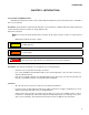
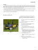
Introduction CHAPTER 1: INTRODUCTION Professional Shop Manual intent This Manual is intended to provide service dealers with an introduction to the mechanical aspects of the RZT-S Zero zero-turn mower. Disclaimer: The information contained in this manual is correct at the time of writing. Both the product and the information about the product are subject to change without notice.
RZT-S Zero • ! CAUTION Be prepared in case of emergency: Keep a fire extinguisher nearby Keep a first aid kit nearby Keep emergency contact numbers handy • Replace any missing or damaged safety labels on shop equipment. • Replace any missing or damaged safety labels on equipment being serviced. • Grooming and attire: ! WARNING Do not wear loose fitting clothing that may become entangled in equipment. Long hair should be secured to prevent entanglement in equipment. Jewelry is best removed.
Introduction Assembly Torque specifications may be noted in the part of the text that covers assembly. They may also be summarized in tables along with special instructions regarding locking or lubrication. Whichever method is more appropriate will be used. In some cases, both will be used so that the manual is handy as a quick-reference guide as well as a step-bystep procedure guide that does not require the user to hunt for information.
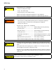
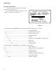
RZT-S Zero Model and Serial Numbers The model and serial number tag can be found under the seat. See Figure 1.2. The serial number is located to the right of the model number as shown above. See Figure 1.2. Meets ANSI B71.1-2003 Safety Standard _____________________ MODEL NUMBER DOM SERIAL NUMBER 17AV2EDS010 EZT-S Zero 10/2012 1J142H20124 J142H20124 CUB CADET LLC P.O.BOX 361131 CLEVELAND,OHIO 44136 Figure 1.2 The model number is 17AV2EDS010. The break down of what the number mean is as follows: 1 ...
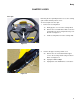
Body CHAPTER 2: BODY Floor pan Removing the floor pan will provide access to the steering gears and the throttle position sensor. To remove/replace the floor pan: 1. Remove the steering wheel: 1a. Gently pry the cover off of the steering wheel. 1b. Remove the screw and washer that secures the steering wheel to the steering shaft using a 1/2” wrench. See Figure 2.1. 1c. Lift the steering wheel off of the steering shaft. Screw Figure 2.1 2. Remove the upper steering column cover: 2a.
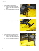
RZT-S Zero 3. Remove the brake pedal: See Figure 2.3. 3a. Remove the screw that secures the brake pedal to the pedal shaft bell crank using a 1/2” wrench. 3b. Unhook the brake pedal from the bell crank. Brake pedal Pedal shaft bell crank Figure 2.3 4. Remove the screw that secures the reverse pedal using a 1/2” wrench. See Figure 2.4. Reverse pedal Figure 2.4 5. Remove the forward drive pedal: See Figure 2.5. 5a.
Body 6. Remove the lower steering column cover by removing the two screws, indicated by the arrows in Figure 2.6, using a T-30 torx driver. 7. Remove the nine screws that hold the floor pan to the frame using a T-30 torx driver. 8. Lift the floor pan off of the mower. 9. Install the floor pan by following the previous steps in reverse order. Figure 2.
RZT-S Zero Left pod Remove the left pod to gain access to the control panel and the charger door switch. To remove/replace the left pod: NOTE: The control panel is nested inside the left pod. ! CAUTION The RZT-S Zero is equipped with a 48 volt system. Removing the pods will expose the high voltage wiring. 1. Disconnect the battery pack’s positive lead from the contactor assembly: 1a. Remove the three screws, indicated by the arrows in Figure 2.
Body 2. Remove the two screws, indicated by the arrows in Figure 2.10, from the underside of the pod using a 3/8” wrench. 3. Remove the rear battery cover by following the procedures described in Chapter 6: Battery Pack and Charger. 4. Remove the two screws, indicated by the arrows in Figure 2.11, from the inboard side of the pod using a T-30 torx driver. 5. Disconnect the charger harness. 6. Remove the screw from the front of the pod using a T-30 torx driver. See Figure 2.12. Figure 2.
RZT-S Zero 7. Lift the pod enough to gain access to the charger door switch. 8. Disconnect the charger door switch. See Figure 2.13. 9. Lift the pod off of the mower. 10. Install the pod by following the previous steps in reverse order. Charger door switch NOTE: Ensure that the charger harness is reconnected when installing the left pod. It is possibly to reassemble the mower with the charger disconnected. It will run but will not charge the batteries. 11.
Body Right pod Remove the right pod to gain access to the PTO and key switches. To remove/replace the right side pod: ! CAUTION Figure 2.14 The RZT-S Zero is equipped with a 48 volt system. Removing the pods will expose the high voltage wiring. 1. Disconnect the battery pack’s positive lead from the contactor assembly by following the procedures described in the left pod section of this chapter. 2.
RZT-S Zero Seat To remove the seat: NOTE: The seat and seat bracket must be removed to remove the seat box top plate or the front battery bracket. 1. Seat switch harness Slide the seat all the way to the rear most position. Seat switch NOTE: If the seat is not all the way back, the seat will hit the front battery cover when the seat is tipped forward. 2. Tip the seat forward. 3. Pull the excess reverse switch harness from the slot in the slot in the seat bracket. See Figure 2.17. 4.
Body Seat box assembly The RZT-S Zero has a bolt together seat box assembly. The individual parts of the seat box are serviced separately, not as one complete assembly. This section will be divided into three sections to cover the service procedures for the three main parts of the seat box assembly.
RZT-S Zero 9. Remove the front battery bracket: 9a. Lower the mowing deck to its lowest setting. 9b. Remove the four screws, indicated by the arrows in Figure 2.20, using a 1/2” wrench. 9c. Reaching underneath the mower’s frame, remove the nuts from the three carriage bolts indicated by the arrows in Figure 2.20. 9d. Lift the bracket over the seat bracket studs and off of the mower. Figure 2.20 10. Remove the six screws, indicated by the arrows in Figure 2.21, using a 1/2” wrench. 11.
Body Seat box front main section NOTE: There are only two reasons to remove the seat box front main section: • To replace the deck lift shaft • Physical damage to the seat box front main section To remove/replace the seat box front main section: ! CAUTION The RZT-S Zero is equipped with a 48 volt system. Removing the pods will expose the high voltage wiring. Blue cable 1.
RZT-S Zero 4. Disconnect the negative cable from the master ground bus using a 9/16” wrench. See Figure 2.24. Master ground bus NOTE: The master ground bus has an over sized stud to minimize the possibility of improper wiring. 5. Fish the negative cable through the opening in the seat box assembly. 6. Fish the positive cable through the opening in the seat box assembly. Figure 2.24 7. Disconnect the VCM harness from the contactor assembly. See Figure 2.25. 8.
Body 10. Remove the two screws, indicated by the arrows in Figure 2.27, that hold down the front battery tray using a 1/2” wrench. 11. Slide the battery tray out of the seat box assembly. Figure 2.27 12. Remove the hex screw from the front of the seat box assembly using a 1/2” wrench. See Figure 2.28. Torx screw 13. Remove the two pan head screws using a T-40 torx driver. Hex screw Figure 2.28 14. Remove the hex screw, indicated by the arrows in Figure 2.
RZT-S Zero NOTE: The front main and rear seat box assemblies can be removed together. If both assemblies are being removed, skip to step 16. 15. Remove the screw, indicated by the arrows in Figure 2.30, that secures the left side of the front main assembly to the rear assembly using a 1/2” wrench. Figure 2.30 16. Support the deck so that the weight is removed from the deck lift system.
Body NOTE: If the front main seat box assembly is being replaced: • Cut off the speed nuts that attach the seat bracket studs to the front main seat box assembly. See Figure 2.33. • Slide the stud assembly out of the front main seat box assembly. Speed nuts • Install the stud assembly in the new front main seat box assembly. 21. Install the front main seat box assembly by following the previous steps in reverse order. Figure 2.33 22. Test run the mower in a safe area before returning it to service.
RZT-S Zero Seat box rear section To remove/replace the seat box rear section: 1. Remove the batteries by following the procedures described in Chapter 6: Battery Pack and Charger. NOTE: The front main and the rear seat box sections can be removed as one assembly. If both sections are to be removed as one, following procedures in the front main seat box assembly then jump to step 3. 2. Remove the seat box top plate by following the procedures described in the seat box top plate section of this chapter.
Body 3d. Remove the four screws that hold the control panel bracket to the mower using a 3/8” wrench. See Figure 2.37. 3e. Lift the control panel and the bracket off of the mower. Do not remove the controller covers. There are precharge capacitors inside each of the controllers. These capacitors will hold a charge large enough to shock the technician and/or damage the controller even after the batteries are disconnected. ! CAUTION Figure 2.37 4.
RZT-S Zero 8. Remove the screw that holds the left rear finger guard to the frame using a 1/2” wrench. See Figure 2.40. 9. Slide the finger guard off of the mower. Left rear finger guard Figure 2.40 10. Remove the six screws that hold the rear section to the frame using a 1/2” wrench. See Figure 2.41. NOTE: If the front main and the rear sections are being removed as one assembly, skip to step 13. 11. Remove the four elevator bolts and nuts using a 1/2” wrench. 12.
Brakes and Drive System CHAPTER 3: BRAKE AND DRIVE SYSTEM Brake system description The RZT-S Zero has an electric hub motor that drives a drop axle at each rear wheel. The RZT-S Zero uses regenerative braking to stop or slow the mower. Regenerative braking is when the power is removed from the motor. As the motor continues to spin, it will generate power. That power is sent to the batteries to help recharge them.
RZT-S Zero Brake adjustment NOTE: When performing a brake adjustment, inspect the brake components for signs of wear or damage. NOTE: Brakes that are dragging will affect battery run time and can mimic a bad battery pack. 1. Test the operation of the brakes: See Figure 3.3. 1a. Turn the mower off. 1b. Set the parking brake by depressing the brake/clutch pedal and pushing-down on the parking brake pedal. 1c. Attempt to push the tractor.
Brakes and Drive System Brake puck/rotor replacement On RZT-S Zeros, the brake pucks are wearing parts that will need to be serviced from time to time. If a mower is operated with the parking brake dragging, the pucks will wear out rapidly and the brake rotor will develop hot spots. If the mower is operated long enough, the rotor may have grinding marks on it with excessively worn pucks. ! CAUTION If the rotor shows hot spots or any other signs of damage, including warpage, it must be replaced.
RZT-S Zero 7. Remove the caliper mounting screws using a 3/8” wrench. See Figure 3.7. 8. The outboard brake puck should fall out as the brake caliper is removed. If it did not, it can be removed now. Mounting screws Figure 3.7 9. Slide the brake rotor off to reach the inboard brake puck. See Figure 3.8. Rotor Figure 3.8 10. With the caliper on a work bench, remove the brake puck, backing plate and the two brake pins. See Figure 3.9. 11. Check for free movement of the brake pins.
Brakes and Drive System 14. Place a new brake puck into the recess in the transmission. Use a piece of scotch tape to hold it in place. 15. Slide the brake rotor in place, shoulder out. 16. Place a new puck into the caliper. NOTE: A piece of scotch tape may be used to hold the new brake pucks in place for assembly. The tape will grind away when the brakes are applied. See Figure 3.10. 17. Mount the brake caliper to the transmission.
RZT-S Zero Brake shaft assembly To remove/replace the brake shaft:. 1. Lift and safely support the rear of the mower. 2. If the parking brake is set, release it. 3. Disconnect the brake shaft return spring. See Figure 3.11. Brake shaft return spring Figure 3.11 4. Disconnect the three rods that attach to the brake shaft by removing the bowtie clips. See Figure 3.12. Rods Figure 3.12 5. Remove the E-rings from the ends of the brake shaft. See Figure 3.13. 6.
Brakes and Drive System Drop axle and hub motor assemblies The drop axle assemblies perform three functions: • The drop axle assemblies are a gearbox that will transmit the power of the hub motor at a reduced speed to the drive wheels. • They facilitate mechanical braking. • The drop axle contains a dog clutch assembly to disconnect the hub motor from the drive wheel. This allows the mower to be pushed by hand.
RZT-S Zero 6. Remove the two screws that hold the top of the drop axle mounting bracket to the frame using a 1/2” wrench. See Figure 3.16. Screws Figure 3.16 7. Disconnect the brake rod by removing the bow tie clip and sliding the rod out of the brake shaft’s bell crank. See Figure 3.17. Bowtie clip Brake rod Figure 3.17 8. Unhook the brake rod from the brake spring. 9. Unhook the brake spring from the cam arm. See Figure 3.18. Brake spring Figure 3.
Brakes and Drive System 10. Disconnect the brake shaft return spring. See Figure 3.19. Brake shaft return spring Figure 3.19 11. Spring Unhook the spring from the drive release rod. See Figure 3.20. 12. Slide the rod out of the mower. Figure 3.20 13. Safely support the drop axle assembly. Screws 14. Remove the two screws that hold the side of the drop axle mounting bracket to the frame using a 1/2” wrench. See Figure 3.21. Figure 3.
RZT-S Zero 15. Remove the two screws that attach the top support plate to the drop axle using a 1/2” wrench. See Figure 3.22. Screws Figure 3.22 16. Remove the bottom support plate. See Figure 3.23. Bottom support plate Figure 3.23 17. While supporting the drop axle assembly, remove the two nuts that hold the motor bracket to the frame using a 1/2” wrench. See Figure 3.24. 18. Lower the drop axle assembly out of the mower. Nuts Figure 3.
Brakes and Drive System 19. Place the drop axle assembly on a workbench. 20. Remove the two screws that hold the motor bracket to the motor using a 1/2” wrench. See Figure 3.25. 21. Lift the bracket off of the assembly. Screws Figure 3.25 22. Remove the four screws that hold the hub motor to the drop axle using a 1/2” wrench. See Figure 3.26. NOTE: There are two alignment pins between the motor and the drop axle. 23. Gently pry the motor off of the drop axle.
RZT-S Zero Rebuilding the drop axles 1. Remove the drop axle by following the procedures described in the previous section of this chapter. 2. Remove the patch bolt and washer that holds the hub to the axle shaft using a 9/16” wrench. See Figure 3.28. 3. Remove the brake and rotor assembly by following the procedures described in the brake puck/rotor replacement section of this chapter. Figure 3.28 4. Remove the push nut that secures the by-pass lever to the by-pass fork. See Figure 3.29.
Brakes and Drive System Drive axle 9. Slide the bushing and the bearing off of the drive axle. 10. Remove the thrust bearing. Spacer 11. Remove the nut securing the drive gear to the drive axle. See Figure 3.31. NOTE: The nut is installed with Loctite #271 thread-locker. Nut Ball bearing Bushing Needle bearing Drive gear Figure 3.31 By-pass fork 12. Remove the brake shaft assembly. See Figure 3.32. Brake shaft assembly Figure 3.32 spur gear 13. Slide the bushings off of the brake shaft.
RZT-S Zero 16. Separate the spur gear from the brake shaft by removing the retaining ring. See Figure 3.34. Retaining ring Figure 3.34 17. Remove the bearing. See Figure 3.35. 18. Remove the input spur gear. Input spur gear Bearing Figure 3.35 Notch 19. Clean and inspect all for the parts for damage and signs of wear. NOTE: Any parts that have damage or signs of wear must be replaced. 20. Re-assemble the drop axle by following the previous steps in reverse order.
Brakes and Drive System A = 1/4-20 x 1.00” B = 1/4-20 x 1.25” C = 1/4-20 x 1.50” D = 1/4-20 x 2.00” B D B D NOTE: Apply Loctite #271 or an equivalent thread-locker to the threaded section of the drive axle. Tighten the nut that secures the drive gear to a torque of 42 - 50 ft lbs. (56 - 68 Nm). NOTE: Fill the drop axle with 10.5 ounces of 737-0300A DurinaTM grease. C C A NOTE: The drop axle has four different length screws securing the housings together. Figure 3.
RZT-S Zero 38
Steering CHAPTER 4: STEERING Introduction The steering on the RZT-S Zero mower is similar to that of other mowers with Cub Cadet’s Syncro Steer Technology. The Syncro Steer Technology steers by: 1. It steers like any other riding mower by turning the front wheels. 2. It controls the speed and direction of rotation of the rear wheels. On the RZT-S Zero this is accomplished by: • A hall effect sensor on the left front wheel yoke sends a signal to the Vehicle Control Module (VCM).
RZT-S Zero 6. Install a 1/4” alignment pin in the left segment gear. See Figure 4.2. 7. Install a 1/4” alignment pin in the right segment gear. 1/4” Alignment pin Figure 4.2 8. Remove the axle casting covers. 9. Insert the axle casting (5/16”) alignment pins into the alignment holes in both axle castings. See Figure 4.3. Alignment pin Figure 4.3 10. Adjust the ball joints on the threaded drag links to align them with the holes in the segment gears. See Figure 4.4. 11.
Steering Front wheels Remove/ replace the front wheels: Axle bolt 1. Lift and safely support the front end of the riding mower. 2. Remove the axle bolt and nut using a pair of 3/4” wrenches. See Figure 4.5. Figure 4.5 3. Slide the tire and wheel assembly out of the yoke. NOTE: There is a short spacer on each side of the wheel. The short spacers slide over the long spacer that the axle bolt passes through. See Figure 4.6. Long spacer 4. Slide the long spacer out of the wheel bearings.
RZT-S Zero To replace the front wheel bearings: 1. Lift and safely support the front of the mower. 2. Remove the front wheel by following the procedures describe in the previous section of this chapter. 3. Drive the bearings out of the wheel hub using a drift or pin punch. See Figure 4.7. Punch Figure 4.7 4. Drive in the new bearings using a brass punch or a tube that has the same O.D. as the bearing. See Figure 4.8. 5. Install the front wheel. 6.
Steering Front yokes To remove/ replace the front yokes: Yoke cover NOTE: There is a magnet in the head of the screw that holds the left yoke in place. This screw should not be removed unless absolutely necessary. 1 Lift and safely support the front of the mower. 2. Remove the front wheel by following the procedures in the front wheel section of this chapter. 3. Remove the two screws that hold the yoke cover in place using a 7/16”. See Figure 4.9. 4.
RZT-S Zero Magnet 7. Remove the hex screw using a 9/16” wrench. See Figure 4.12. NOTE: The yoke will slide out as the screw is removed. NOTE: Do not use an impact wrench on the left side. The impact pulses can cause the magnet to pop out of the screw head. 8. Remove the washers from the top of the axle casting. NOTE: If replacing the yoke, remove the steering gear by following the procedures described in the steering gear section of this chapter. Left Right Figure 4.12 To install the yoke: 1.
Steering For the Left yoke 5a. Install the hex screw with the magnet, lock washer and the fender washer. 5b. Apply a small amount of a thread locking compound such as Loctite® 262 (red) to the threads of the hex screw with the magnet. 5c. Tighten the hex screw holding the yoke to a torque of 25 ft lbs (34 Nm). 5d. Turn the hex screw with the magnet until the north pole of the magnet (the side with the red mark) is perpendicular with the frame, facing in. See Figure 4.15.
RZT-S Zero Removal of the steering gears To remove the steering gears: 1. Remove the floor pan, following the procedures described in Chapter 3: Body. 2. Remove the nut from the bolt that holds the drag link to the inboard steering gear using a pair of 9/16” wrenches. See Figure 4.17. Nut Inboard steering gear Figure 4.17 3. Remove the front yokes by following the procedures in the front yokes section of this chapter. 4.
Steering NOTE: The same part number gear is used on both yokes. If the gear is to be used on the left yoke, install it so that the LH stamped into the gear is facing up. If the gear is to be used on the right yoke, install it so that the RH stamped into the gear is facing up. See Figure 4.20. 7. Slide the gear off of the yoke. Figure 4.20 Hex screw 8. Remove the hex screw that holds the steering gear to the shaft using a 9/16” wrench. See Figure 4.21. 9. Slide the steering gear off of the shaft.
RZT-S Zero Installation and timing of the steering gears To install and time the steering gears: 1. Install the alignment pins by following the procedures described in the wheel alignment section of this chapter. 2. Slide the double-D of the steering gear shaft into the double-D hole of the inboard steering gear. “RH” facing up NOTE: The inboard steering gear is the same part number for both sides. If the gear is used on the left hand side, the LH stamped into the gear must be facing up.
Steering 9. Tighten the hex screw holding the steering gear shaft to a torque of 17 ft lbs (23 Nm). Socket headed cap screw 10. Attach the outboard steering gear to the yoke with the socket headed cap screw using a 1/4” hex key. See Figure 4.24. 11. The socket head cap screw acts as the turn stop for the front wheels. NOTE: The socket head cap screw acts as a travel stop. Do not replace it with a hex head screw. 12.
RZT-S Zero Drag links To remove a drag link: 1. Remove the floor pan by following the procedures described in Chapter 3: Body. 2. Turn the steering wheel so that the drag links outer ball joint is accessible through the opening in the frame. See Figure 4.25. 3. Loosen the both the inner and outer drag link ball joint jam nuts using a 9/16” wrench. 4. Remove the outer ball joint using a pair of 9/16” wrenches.
Steering To install a drag link: 1 Install the jam nuts on the new drag link. NOTE: Thread the jam nuts all the way to the unthreaded section of the drag link. 2. Install the ball joint ends on the drag link. Alignment pin NOTE: The ball joint ends should be threaded on to the drag link the same number of turns as was required to remove the old ones. 3. Remove both of the yoke covers. 4. Attach the outer ball joint to the inboard sector gear. 5.
RZT-S Zero Steering sensor To remove/replace the steering sensor: NOTE: The function and troubleshooting procedures for the steering sensor are covered in Chapter 5: Electrical System. 1. Remove the floor pan by following the procedures described in Chapter 3: Body. 2. Remove the two screws that hold the yoke cover in place using a 7/16”. See Figure 4.31. Yoke cover NOTE: There are two spacers with star washers under the cover. Figure 4.31 3. Disconnect the steering sensor pigtail. See Figure 4.32.
Steering 5. Remove the nuts and bolts that hold the sensor to the sensor bracket using a #2 Phillips screwdriver and a 1/4” wrench. See Figure 4.34. Bolts Figure 4.34 6. Install a new sensor to the sensor bracket using the nuts and bolts that held the old one in place. 7. Place the two flat washers on the axle casting so that the holes in the washers line up with the screw holes. See Figure 4.35. Washers 8. Install the steering sensor and bracket. 9. Check the steering sensor air gap.
RZT-S Zero 10. Plug the steering sensor into the harness. 11. Install the yoke cover: 11a. Place the two spacers over the screw holes in the axle casting with the necked in side facing up. 11b. Place the star washers on top of the spacers. 11c. Position the cover for installation. 11d. Install the screws using a 7/16” wrench. 12. Install the floor pan by following the procedures described in Chapter 2: Body. 13.
Steering Throttle Position Sensor (TPS) sensor To remove/replace the TPS: 1 Remove the floor pan by following the procedures described in Chapter 2: Body. NOTE: Disconnecting the battery pack is not necessary when working with the sensors under the floor pan. They run on a 5 volt signal. TPS pigtails 2. Disconnect the two TPS pigtails from the VCM harness. See Figure 4.37. Figure 4.37 3. Disconnect the TPS actuator rod from the TPS by removing the hair pin clip. See Figure 4.38.
RZT-S Zero Steering and TPS calibration NOTE: The mower must be calibrated every time: • VCM is replaced • Steering sensor is removed/replaced • TPS is disconnected To calibrate the mower: 1. Hold down the mow in reverse and the headlight buttons while turning the key to the “ON” position. 2. Turn the steering wheel to the left until the axles hit the hard stop. NOTE: Watch the sensor input while turning the steering wheel.
Electrical System CHAPTER 5: ELECTRICAL SYSTEM Introduction The RZT-S Zero has a 48 volt electrical system. This system is an isolated or “fully floating” system. This means that the electrical system is not grounded to the chassis and is insulated from the non-electrical components of the mower.
RZT-S Zero In this system the VCM is the central computer that controls everything on the mower and acts as the user interface for most of the system. The VCM receives constant power from the battery pack, by a lead from the contactor assembly on the control panel. A constant 48 volts passes through the VCM going to the key switch. If the key switch is in the “ON” position, the 48 volts will return to the pin 9 of the VCM’s 16 pin connector VCM.
Electrical System • 150 amp main system fuse: This fuse is in-line on the positive cable, between the battery pack and the control panel. See Figure 5.4. NOTE: If this fuse is blown, there is a major short in the system. Check for chaffed wires or a shorted battery pack before replacing the fuse. 150 Amp fuse NOTE: The torque on the main fuse connections is 45 - 55 in lbs (5 - 6 Nm). Figure 5.
RZT-S Zero • Hub motors: The hub motors are 3-phase, brushless DC motors that are mounted onto a pair of drop axles to drive the rear wheels. See Figure 5.7. NOTE: The motor harness is part of the motor and can not be serviced. Any damage to the wires or the connector and the whole motor will need to be replaced. Hub motor Figure 5.7 • Seat switch: The seat switch used on the RZTS Zero is a Double Pole Single Throw (DPSPT) switch. Unlike most MTD seat switches, this switch is a Normally Open (N.O.).
Electrical System • Brake switch: The brake switch is a SPDT switch with one set of contacts that are Normally Open (N.O.) and the other set of contacts that are Normally Closed (N.C.). See Figure 5.10. Brake switch NOTE: The red wire with a white trace carries a 5 volt signal to one of the NC tabs of the brake switch. When the brake pedal is released, a voltage signal will pass through the brake switch and flow to the VCM through the brown wire with a white trace. Figure 5.
RZT-S Zero • PTO switch: There is a standard PTO switch mounted in the right pod. The switch is used to send a signal to the VCM to turn the deck on or off. See Figure 5.13. NOTE: A red wire with a white trace splits and carries 5 volts to the “B” and “C” terminals of the PTO switch. A black wire with a white trace and a white wire with a black trace carry the input signals back to the VCM. PTO switch • Battery pack: The battery pack will be covered in Chapter 6: Batteries. Figure 5.
Electrical System Electric motors The electric motors used on the RZT-S Zero are 3 phase, brushless, DC motors. This type of motor allows for fine control of the motor’s speed and torque. The construction of the hub and deck motors are very similar. The biggest difference between the two is the rotor shaft. The hub motor is splined and the deck motor is keyed. The deck motor also has extra bearings supporting the shaft. The stator is similar to an alternator stator found under a flywheel.
RZT-S Zero • DC Motor: These motors use DC voltage pulses that will go in one phase as a positive pulse and leave another as a negative pulse. The inputs and outputs are constantly switching so that one phase will be positive, one will be negative and the third phase will be zero. See Figure 5.16. 5 6 7 Figure 5.
Electrical System Vehicle Control Module (VCM) 1. Screws Remove the upper steering column cover: 1a. Remove the six screws that hold the upper cover to the steering column using a T-30 torx driver. See Figure 5.17. 1b. Carefully lift the upper cover off of the steering column. NOTE: The upper cover is still tethered to the mower by the VCM harness. 1c. Position the upper cover so that the VCM harness is slack. 1d. Unplug both of the VCM harness connections. Figure 5.
RZT-S Zero VCM Connector Pin Designations Pin A1 A2 A3 A4 A5 A6 A7 A8 A9 A10 A11 A12 B1 B2 B3 B4 B5 B6 B7 B8 B9 B10 B11 B12 B13 B14 B15 B16 66 Name LIGHTS+ LIGHTSSPEAKERSPEAKER+ COMMUNICATION COMMUNICATION RETURN BATTERY+ PRE-CHARGE CONTACTORCONTACTOR+ LOGIC BRAKE CHARGE SEAT1 SEAT2 PTO1 PTO2 NOT USED SENSOR+ RUN NOT USED RUN SUPPLY STEERSTEER+ THROTTLETHROTTLE1 THROTTLE2 I/O Output Return Return Output Bus Bus Input Input Input Input Input Input Output Input Output Input Input Input Input Input Voltag
Electrical System Control panel NOTE: The control panel is serviced as one assembly during the warranty period. Outside of warranty, the individual controllers can be replaced. NOTE: The contactor assembly is not serviceable and should not be opened. This would void the warranty. ! CAUTION Before disconnecting any electrical component, take precautions to prevent the component or the wires attached to it from shorting out.
RZT-S Zero 2. Remove the left pod by following the procedures described in Chapter 2: Body. 3. Disconnect the 12 pin harness connector from the contactor assembly. 4. Disconnect the negative battery pack cable from the master ground bus. See Figure 5.21. Master ground bus The battery pack’s negative lead is still hot. Take measures, such as taping up the cable lug with electrical tape, to prevent the cable end from making contact with any metal surface on the mower ! CAUTION 5.
Electrical System 7. Motor connectors Disconnect the motor harness connectors. See Figure 5.23. NOTE: Do not disconnect the five wires that go under the controller cover. Do not remove the controller covers. There are pre-charge capacitors in the controllers. These capacitors will hold a charge after the harnesses are disconnected. ! CAUTION Figure 5.23 NOTE: Do not disconnect the harness that runs from the contactor assembly to the controllers. It is serviced as part of the control panel. 8.
RZT-S Zero Controllers To remove/replace a controller NOTE: The control panel is serviced as one assembly during the warranty period. Outside of warranty, the individual controllers can be replaced. NOTE: The contactor assembly is not serviceable and should not be opened. This would void the warranty. 1. Disconnect the battery pack’s positive lead from the contactor assembly: 1a. Remove the three screws that hold the left access cover in place using a 1/2” wrench. See Figure 5.25. Figure 5.25 1b.
Electrical System Test light 4. Discharge the pre-charge capacitors. NOTE: Do not use a high impedance test light for this procedure. There is a very high likelihood that the capacitor’s charge will damage it. Figure 5.28 Figure 5.29 4a. Remove the controller cover. 4b. Attach an incandescent test light to the negative (black) wire attached to the controller. 4c. Touch the probe of the test light to the positive (red) wire connection on the controller.
RZT-S Zero Troubleshooting Unlike all other mowers produced by MTD, the RZT-S Zero has an insulated 48 volt system. This means that the usual methods of troubleshooting will not apply to this mower. On this mower the system can be boiled down to this: • Switches and sensors send input signals to the VCM. • The VCM interprets the data. • The VCM sends instructions to the control panel. • The control panel carries out the instructions.
Electrical System No Power/VCM does not light up When the key switch is turned on, the VCM should light up. If it does not: 1. Open the charger door on the mower. 2. Measure the voltage across the charger port with a DMM set to the DC volts scale. See Figure 5.30. • If the DMM reads zero volts, check the charger port’s fuse and charge the batteries. • If the DMM reads below 42 volts, charge the batteries.
RZT-S Zero 7. Remove the VCM by following the procedures described in the Vehicle Control Module (VCM) section of this chapter. 8. Install the harness break out adapters. 9. Measure the voltage across pins 7 and 8 of the 12 pin VCM connector. See Figure 5.33. 12 pin adapter NOTE: The pigtail wires on the break out adapters are numbered to match the pin they are attached to. • If the DMM reads battery voltage both the power and the return side of the power circuit are functional.
Electrical System No Start Icon This screen indicates that the VCM is waiting for the operator to start the mower. The VCM will stay at this screen until it checks all of its ports and the controllers turn on (should take approximately 2 seconds). If the operator holds the start button down, but the mower does not start: NOTE: The round icon on the screen should turn dark while the start button is depressed. If it does not, the VCM is faulty. See Figure 5.34. 1. Check VCM for fault codes.
RZT-S Zero • The VCM has lost communication with the steering sensor. • The VCM cannot understand the signal it is getting from the steering sensor. • The steering sensor jumps from one end of its scale to the other. To troubleshoot the steering sensor: 1. Turn the ignition key to the “OFF” position. 2. Depress the mow in reverse and headlight buttons with one hand while turning the ignition key to the “ON” position with the other. This will bring up the steering calibration screen.
Electrical System 3. Sensor Rotate the steering wheel while observing the VCM’s screen. A. The steering angle jumps up and down in value: • Check the sensor’s air gap by following the procedures described in Chapter 4: Steering. • Check for steering yokes ability to move in and out of the axle casting. NOTE: Travel of the left yoke will cause the magnet to move in and out of the steering sensors range.
RZT-S Zero Throttle Position Sensor (TPS) faults The TPS assembly consists of two rotary hall effect sensors that are from the same series as the steering sensor. The TPS bracket has an arm that holds a magnet. As the arm moves, it rotates the magnet which is sandwiched between the two sensors. See Figure 5.40. Magnet TPS lever 5 volts leaves pin 8 of the VCM’s 16 pin connector. The wire carrying the 5 volts splits and carries 5 volts to pin 1 of all the sensor connectors on the mower.
Electrical System NOTE: If one or both of the sensors reads “0”, the VCM can not see that sensor(s) because it is either disconnected or the harness is damaged. • Remove the floor pan enough to gain access to the TPS assembly connectors. NOTE: If either of the TPS connectors are disconnected, plug them in and check and see if the VCM can see the sensor now. If it was connected: • Disconnect the TPS sensors. • Set a DMM to read DC voltage.
RZT-S Zero NOTE: If the one or both of the sensors jump from one end of the scale to the other: • Remove the two Phillips headed screws that hold one of the hall effect sensor to the TPS bracket. See Figure 5.44. • Slide the magnet out of the TPS lever. • Rotate the magnet 180o and re-insert it in the TPS lever. • Re-install the hall effect sensor. • Calibrate the TPS by following the procedures described in Chapter 4: Steering. Screws Figure 5.
Electrical System Motor faults To troubleshoot motor faults: NOTE: When troubleshooting the motors, hub or deck, the procedures are basically the same. 1. Inspect the motor: • For a deck motor fault, sharpen the blades and remove any debris from motor. NOTE: If there are any signs of impact damage on a blade, check the motor for a bent shaft. • For a hub motor fault, check and adjust the brake pads by following the procedures described in Chapter 3: Brake and Drive System.
RZT-S Zero 3. Test run the mower to verify any faults NOTE: There are several service screens that will allow the technician to observe the system conditions and motor performance in real time. 4. Depress the down arrow seven times, until the motor speeds screen appears. See Figure 5.46. Deck Hub NOTE: This screen will display the speed of all four motors. 5. • The deck motors should be spinning at the same speed.
Electrical System 6. Depress the down arrow button one time to bring up the base temp. screen. See Figure 5.48. NOTE: The screen shows the temperature of each controller. If there is a temperature that is drastically different than the rest, refer to the control panel trouble shooting section. Figure 5.48 7. Depress the down arrow button one time to bring up the motor temp. screen. See Figure 5.49.
RZT-S Zero Control panel faults The control panel consists of the: • The contactor assembly • The master ground bus • 4 controllers • A communication harness • Aluminum back plate The contactor assembly can be thought of as the main power distribution center of the system. There is a master relay and four fused leads that sends 48 volts to the controllers and the master ground bus is the common grounding point for the voltage to return to the batteries. See Figure 5.51.
Electrical System To determine if the contactor assembly is functioning properly: 1. Remove the left pod by following the procedures described in Chapter 2: Body. NOTE: Do not disconnect the battery pack while removing the pod. Break out adapter 2. Install a jumper in the charger door switch connector. 3. Install the 12 pin harness breakout adapter between the harness and the contactor assembly. See Figure 5.52. 4. Remove the controller covers 5. Set the parking brake. 6.
RZT-S Zero C. If all of the controllers read battery voltage, the pre-charge voltage is reaching the controllers, but this does not mean that the master relay is functional. To test the master relay: 1. Set a DMM to measure DC volts. 2. Place the negative probe in pin 3 of the breakout adapter. See Figure 5.55. 3. Place the positive probe in pin 4 of the breakout adapter. 4. While sitting in the seat with key switch in the “ON” position, depress the start button while watching the DMM.
Electrical System The contactor assembly also distributes the VCM’s signals to and from the controllers: Jumper • The VCM actually communicates with the controllers by a series of positive and negative 5 volt pulses that travel through pins 11 and 12 of the contactor’s main harness connection. These signals are carried to the controllers through the yellow and gray wires in the communication harness. NOTE: All four controller have the same programing.
RZT-S Zero Switch faults The VCM sends 5 volts out pin 8 of the 16 pin connector. This 5 volts goes to the: • Charger door switch • Brake switch • TPS assembly • Steering sensor • PTO switch • Seat switch (via the charger door switch) NOTE: The TPS, charger door, seat and PTO switches have dual circuits as a redundancy and are considered critical safety inputs. NOTE: The charger door switch is considered a critical safety switch and gets its redundancy by splitting its output.
Electrical System 8. With the charger door closed, measure the voltage from pin 7 (- probe) of the 12 pin connector of the VCM to pins 2 and 4 of the seat switch connector. NOTE: Removing the seat switch will make it easier to close the seat switch for testing. 9. 4 3 2 1 With the charger door closed and the seat switch closed, measure the voltage from pin 7 (- probe) of the 12 pin connector of the VCM to pin 1 and 3 of the seat switch connector. See Figure 5.61.
RZT-S Zero 3. Inspect the charger door switch connection. 4. Turn the key switch to the “ON” position. 5. Set a DMM to measure DC volts. 6. Back probe the red wire with a white trace using the positive probe of the DMM. See Figure 5.63. 7. While observing the DMM, place the negative probe on the master ground bus. 8. 9. • If the reading is 4 - 5 volts, the VCM’s signal is reaching the switch. • If the reading is 0, the VCM’s signal is not reaching the switch. Skip to step 10.
Electrical System Brake switch The brake switch receives 4 - 5 volts through a red wire with a white trace. A brown wire with a white trace carries the voltage from the N.O. contact of the brake switch to pin 1 of the VCM’s 16 pin connector. If there is a brake switch fault: 1. Remove the VCM by following the procedures described in the Vehicle Control Module (VCM) section of this chapter. 2. Install the harness break out adapters. See Figure 5.65. 3. Set the parking brake 4.
RZT-S Zero PTO switch The PTO switch receives 4 - 5 volts at B-Com and CCom through a red wire with a white trace. When the PTO switch is in the “OFF” state, a black wire with a white trace carries the voltage from the C- N.O. contact of the PTO switch to pin 5 of the VCM’s 16 pin connector. A white wire with a black trace carries the voltage from the B- N.O. contact of the PTO switch to pin 6 of the VCM’s 16 pin connector. If there is a PTO switch fault: 1.
Electrical System 11. Remove screws securing the right pod by following the procedures described in Chapter 2: Body. NOTE: Do not remove the pod. NOTE: Do not disconnect the battery pack while removing the right pod. 12. Lift the pod enough to gain access to the key switch. 13. Push the PTO switch in to the “OFF” position. 14. Turn the key switch to the “ON” position 15. Place the negative probe of the DMM in the socket of pin 7 on the 12 pin breakout adapter. 16.
94 Charger port + - Battery + - + - + Battery Battery Main Fuse Battery VCM contactor Control Panel Controller R Deck Controller L Deck Sensor wires RED +5 VOLTS SIGNAL GROUND BLACK GREEN HALL A HALL B YELLOW BLUE HALL C BROWN Controller THERMISTOR R Hub Controller Heavy Gauge Wires BLUE PHASE W YELLOW PHASE V PHASE U GREEN L Hub Schematic RZT-S Zero
Error codes Message Message type Mower's action Code number (engineering screen)** Trigger Possible causes Display message only Battery power in the Heavy Load range for 10 continuous seconds.
Message type Mower's action Trigger Possible causes Starter disable Won't start until condition met. 0 volts at pin B3 and B4 Seat switch is not being depressed, poor connection, faulty switch, damaged harness To Start: Push blade knob down/off Starter disable Won't start until condition met. 5 volts at pin B5 and B6 PTO switch is ON, defective switch or a short in the harness To Start: Remove foot from drive pedal Starter disable Won't start until condition met.
Message Message type Mower's action Code number (engineering screen)** Trigger Possible causes 97 Operator error Disables Blades 2 One or both of the deck motors are pulling 110 amps or more Too much material being cut, build up of clippings under the deck, binding of the motor, faulty motor or a faulty controller Blades off: Left Deck Fault Blades off: Right Deck Fault Operator error Disables Blades 16 One or both of the deck controllers are at 100o C or more Too much material being cut, b
Message type Mower's action Trigger Possible causes 98 Stopped: Left hub fault / Restart, if problem persists contact service Fault Disables Blades and Drive 32 Motor hall sensor fault Disconnected harness connector, damaged harness, corrosion, faulty motor Overload: Slow down or raise deck Fault Disables Blades and Drive 64 Controller under voltage Battery voltage too low, poor connection, corrosion Stopped: Left hub fault / Restart, if problem persists contact service Fault Disables Bla
Message Message type Mower's action Code number (engineering screen)** Trigger Possible causes 99 Fault Disables Blades and Drive 32768 Instantaneous under voltage Momentary drop in battery voltage from the motor pulling too much current, short bursts Stopped: Right hub fault / Restart, if problem persists contact service Fault Disables Blades and Drive 1 Controller over voltage Batteries over charged, usually from regen.
Message type Mower's action Trigger Possible causes 100 Stopped: Right hub fault / Restart, if problem persists contact service Fault Disables Blades and Drive 128 POST static gating test Controller failure Stopped: Right hub fault / Restart, if problem persists contact service Fault Disables Blades and Drive 512 Instantaneous phase over current Motor pulling too much current, short bursts Stopped: Right hub fault / Restart, if problem persists contact service Fault Disables Blades and Dr
Message Message type Mower's action Code number (engineering screen)** Trigger Possible causes Disables Blades 2 Phase over current Motor pulling too much current, short bursts Blades off: Left deck fault Restart, if problem persists contact service Fault Disables Blades 4 Current sensor calibration Internal controller issue Blades off: Left deck fault Restart, if problem persists contact service Fault Disables Blades 8 Not used Blades off: Left deck fault Restart, if problem persists c
Message type Mower's action Trigger Possible causes 102 Blades off: Left deck fault Restart, if problem persists contact service Fault Disables Blades 2048 Throttle voltage outside range N/A Blades off: Left deck fault Restart, if problem persists contact service Fault Disables Blades 4096 Instantaneous controller over voltage Batteries over charged, usually from regen.
Message Message type Mower's action Code number (engineering screen)** Trigger Possible causes 103 Fault Disables Blades 16 Controller temperature is over 100oC Controller overheating from the motor pulling too much current, usually from being overloaded, faulty controller Blades off: Right deck fault Restart, if problem persists contact service Fault Disables Blades 32 Motor hall sensor fault Disconnected harness connector, damaged harness, corrosion, faulty motor Overload: Slow down or r
Message type Mower's action Trigger Possible causes 104 Blades off: Right deck fault Restart, if problem persists contact service Fault Disables Blades 16384 POST dynamic gating test Controller failure Overload: Slow down or raise deck Fault Disables Blades and Drive 32768 Instantaneous under voltage Momentary drop in battery voltage from the motor pulling too much current, short bursts Stopped: Drive sensor fault / Restart, if problem persists contact service Fault Disables Blades and Dr
Message Message type Mower's action Code number (engineering screen)** Trigger Possible causes Disables Blades and Drive Steering signal drops to or near 0V, or rises to or near 5V.
Message type Mower's action Trigger Possible causes 106 Stopped: Right wheel comm fault / Restart, if problem persists contact service Fault Disables Blades and Drive 256 (or no code if VCM timed out and is not able to read a fault code from the controller.
Message Message type Mower's action Code number (engineering screen)** Trigger Possible causes 107 Stopped: Seat switch fault / Check to see if seat is plugged in / Restart, if problem persists contact service Fault Disables Blades and Drive Interlock1 code 8 code 16 code 24 Dual seat switch inputs are not equal Poor connection, faulty switch, damaged harness Stopped: Seat switch fault / Check to see if seat is plugged in / Restart, if problem persists contact service Fault Disables Blades an
RZT-S Zero 108
Battery Pack and Charger CHAPTER 6: BATTERY PACK AND CHARGER ! CAUTION Batteries produce flammable and explosive gases, particularly during charging. • Do not smoke or allow an open flame or heat source near the battery. • Charge batteries in an open area • Wear eye protection and acid resistant gloves when handling batteries. • Do not allow direct metal contact across the posts. This will produce extreme heat that may cause direct burns or ignite flammable gas.
RZT-S Zero Deep cycle batteries The RZT-S Zero uses deep cycle batteries. Deep cycle batteries look similar to standard automotive lead-acid batteries, but are of a different construction. Automotive batteries can be thought of as sprinters. They are built for a heavy current draw for a short period, and to sit on charge for the rest of the time. Deep cycle batteries are like marathon runners.
Battery Pack and Charger 1g. Open the charger door on the mower. 1h. Measure the voltage across the charger port with a DMM set to the DC volts scale. 1i. Document the battery packs current state of charge on the battery check list. NOTE: Leaving batteries in a fully discharged state will damage them. 2. Test run the mower. • Verify the customers complaint • Check for any fault codes in the VCM Charger port Figure 6.1 3. NOTE: If any fault codes are found, repair those issues first.
RZT-S Zero NOTE: Battery cable corrosion is the most common type of increased resistance circuit failures. NOTE: Lightly coating the battery cable lugs with a petroleum jelly will help prevent corrosion of the battery cables. 7. Perform a visual inspection of the batteries. • Inspect the battery case for signs of damage. Battery cases that excessively bow out in the middle indicate that the battery froze or was over heated and should be replaced.
Battery Pack and Charger Battery testing Typically, there are four major ways to check a battery: • Electrolyte test using a specific gravity tester (hydrometer) to compare the density of the electrolyte in a fully charged battery to the density of water (water = 1.0 s.g.). • Electrolyte test using a refractometer to check the density of the electrolyte by measuring the degree to which light waves bend when passing through the electrolyte.
RZT-S Zero Capacity/discharge test Standard lead acid batteries (starter batteries) are designed to deliver short burst of high current draws. Deep cycle batteries are designed to supply a steady current flow over a long period of time. The batteries capacity is its ability to deliver a fixed current draw over a period of time, measured in amp-hours. An example of this is if a battery supplies 10 amps for 15 hours, the battery would have 150 amp-hours (10 x 15 = 150).
Battery Pack and Charger Charger The RZT-S Zero has a 48 volt system. The mower gets 48 volts through four batteries, wired in series. These batteries form a battery pack and are all charged as one unit. NOTE: Only use the charger that came with the mower to charge the batteries. ! CAUTION Batteries can be dangerous to work around. Here are some precautions that can help prevent injuries to the technician. • Have someone within range of your voice in case of an emergency.
RZT-S Zero 5-STAGE CHARGE NOTE: The 5-state charge and the charger trouble codes sections were extracted from charger’s instruction manual, form number MNL058en Rev. 6. • 3 seconds after connection to AC Power, (and assuming the use of the 120Vac 60Hz model part number 1-48C017xxx-xxxx, set to MODE-2, all 5 charger L.E.D.s will flash on and off, twice, and then the Power L.E.D. and Detection L.E.D. will illuminate. The Detection L.E.D.
Battery Pack and Charger Charger Trouble Codes Under normal charge circumstances, the L.E.D.s operate as follows: • Power On (Red) Illuminates continuously when AC power is present. • Abnormal Shutdown (Red) Normally not illuminated. • Detection Error (Red) If connected to A.C. Power, but not connected to a battery pack, or battery pack is discharged to near 0V, L.E.D. will illuminate to indicate the charger cannot “See” a battery connected.
RZT-S Zero Battery removal/installation ! WARNING This mower has four batteries that need to be installed. They must be installed in a specific order to minimize shorting hazards and to prevent improper wiring of the system. Never let the battery terminals or any live harness connection contact the frame. #ONTROL PANEL "ATTERY "ATTERY "ATTERY "ATTERY Battery Schematic To remove/replace the batteries: 1. Disconnect the battery pack’s positive lead from the contactor assembly: 1a.
Battery Pack and Charger 1b. Positive lead Disconnect the battery pack’s positive lead from the contactor assembly using a 7/16” wrench. See Figure 6.6. Contactor assembly Figure 6.6 The battery pack’s positive lead is still hot. Take measures, such as taping up the cable lug with electrical tape or a plastic bag, to prevent the cable end from making contact with any metal surface on the mower. See Figure 6.7. ! CAUTION positive lead Figure 6.7 Nuts 2. Disconnect the seat switch. 3.
RZT-S Zero 5. Remove the four black shoulder screws that secure the front battery cover to the mower using a T-30 torx driver. See Figure 6.9. Screws Figure 6.9 6. Remove the front bracket: See Figure 6.10. 6a. Lower the mowing deck to its lowest setting. 6b. Remove the lock nuts from the carriage bolts from the underside of the mower. 6c. Remove the three carriage bolts. 6d. Remove the four self tapping screws using a 1/2” wrench. 6e.
Battery Pack and Charger 12. Remove the rear battery cover: 12a. Remove the two screws at the front of the rear battery cover using T-30 torx driver. See Figure 6.12. Screws Figure 6.12 12b. Remove the two nuts and screws that hold the rear of the battery cover in place using a T-30 torx driver and a 7/16” wrench. See Figure 6.13. 12c. Lift the rear battery cover off of the mower. Screws Figure 6.13 Battery tray 13. Remove the nuts from the battery tray’s long J-bolts. See Figure 6.14. 14.
RZT-S Zero 16. Disconnect the jumper wire (green tape) from the two batteries that are standing on end. See Figure 6.15. 17. Disconnect the battery cable with the blue tape. 18. Disconnect the battery cable with the yellow tape. NOTE: The battery cable with the yellow tape is still connected to battery number one. Take measures to prevent the cable from contacting the mower frame. 19. Lift the batteries off of the mower. Figure 6.15 20. Remove the battery bracket: See Figure 6.16. 20a.
Battery Pack and Charger To install the batteries: NOTE: Before installing the batteries, remove the month and year from the label or write the date of installation on the side of the batteries with a permanent marker. This will be helpful in diagnosing the batteries after they have been in service for a while. 1 Positive Yellow tape 1. Insert 1st battery under seat box so that the terminals are down, facing rear of tractor. See Figure 6.18. 2.
RZT-S Zero 9. Insert the battery terminals cover into the slot in the battery tray. Battery terminals cover NOTE: There is a notch in the cover to allow the battery cables to pass through it. This notch should be at the bottom, on the right hand side. See Figure 6.21. 10. Attach top tray using the two long J-bolts. 11. Install the hex flange lock nuts on the J-bolts. Tighten them to a torque of 160 - 200 in lbs (18 - 22 Nm). Notch Figure 6.21 12. 13.
Battery Pack and Charger 17. Install the front bracket: See Figure 6.24. 17a. Lower the mowing deck to its lowest setting. 17b. Slide the front bracket over the two studs for the seat bracket. Self tapping screws 17c. Install the four self tapping screws using a 1/2” wrench. 17d. Install the three carriage bolts. 17e. Install the lock nuts onto the carriage bolts from the underside of the mower. Carriage bolts Figure 6.24 18. Install the rear battery cover: 18a.
RZT-S Zero 19. Install the front cover using the four black shoulder screws. Screws Figure 6.27 Seat switch harness 20. Install the seat: See Figure 6.24. 20a. Set the seat and seat bracket over the studs in the seat box. 20b. Install the two nuts that secure the seat bracket to the mower using a 1/2” wrench. 20c. Run the seat switch harness through the slot in the seat bracket. 20d. Plug the seat switch harness into the seat switch.
ELECTRIC RIDER BATTERY REPLACEMENT CHECK LIST Dealer number _____________ Technician_____________________________ Model number_____________________ Inspection Date_________ Serial number__________________________ Hours __________ NOTE: An Authorization is required from Cub Cadet before the batteries can be replaced under warranty. This check list must be performed prior to calling Cub Cadet for an authorization number and returned with the old batteries.
Charger Trouble Codes Under normal charge circumstances, the L.E.D.s operate as follows: • Power On (Red) Illuminates continuously when AC power is present. • Abnormal Shutdown (Red) Normally not illuminated. • Detection Error (Red) If connected to A.C. Power, but not connected to a battery pack, or battery pack is discharged to near 0V, L.E.D. will illuminate to indicate the charger cannot “See” a battery connected. Check for a blown fuse in the charger harness or a bad connection.
Decks and Lift Shaft CHAPTER 7: DECKS AND LIFT SHAFT Cutting decks The RZT-S Zero comes with a 42” floating deck. The deck is made of 13-gauge stamped steel. The deck is NOT a quick release deck and is not intended to be removed as part of normal service. To remove the deck: NOTE: The deck should only be remove to: • Replace the deck shell • Remove/replace the deck lift shaft. ! CAUTION Hole in frame Front battery The RZT-S Zero is equipped with a 48 volt system.
RZT-S Zero NOTE: Each of the high current connectors coming from the motors are actually three separate connectors that hook onto each other. They can, but do not have to, be separated in order to fish the connectors through smaller openings. See Figure 7.3. NOTE: The high current connectors maybe locked together. The lock must be pried out before separating the individual connectors. NOTE: A diagonal line can be drawn across the three connectors to help ensure they are reassembled in the proper order.
Decks and Lift Shaft Cleaning the deck Clean debris off of the deck every time the mower is used. It is routine maintenance that will make the deck easier to work on and prolong the life of the deck and spindles. ! CAUTION Debris build up on the mower deck is an unsafe condition. The debris traps heat in the motors causing damage to the motor bearings. Debris around the motors can overheat. To clean the deck: 1. Blow all the debris off of the top of the deck using compressed air. 2.
RZT-S Zero Blades The condition of the blades will greatly affect the quality of the cut. The blades should be sharpened and balanced after every five acres, depending on local conditions. A dull blade tears the grass instead of cutting it. Torn grass blades leaves a rough look and makes the grass vulnerable to diseases. Blades need to be examined for damage before sharpening. Blades must be balanced after sharpening to minimize vibrations. Bent blades are a sign of a blade impact.
Decks and Lift Shaft 5. Check the blade adapter, motor shaft and hardware for damage: See Figure 7.9. • The end of the motor shaft should not wobble or orbit when the motor shaft is rotated. • The key in the blade adapter and the keyway in the motor shaft should engage firmly. The blade adapter should not spin on the motor shaft. Blade adapter Figure 7.9 6. • The bowtie shaped boss and embossed pins on the blade adapter should not be deformed.
RZT-S Zero Leveling the deck For the best quality cut, the deck must be level side to side and the front of the deck should be 1/4” lower than the rear of the deck. To level the deck: NOTE: Deck leveling is part of initial mower setup. Before adjusting an out of level deck on a mower that has been used, inspect all of the deck lift and suspension linkages. Move the deck through its full range of travel while checking linkage movement. Repair any damaged or binding linkage before leveling the deck.
Decks and Lift Shaft Front To Rear (pitch) Leveling 1. With the mower parked on a firm, level surface, move the deck to the mid height or most commonly used position using the deck lift pedal. Rotate the blade nearest the discharge chute so that it is parallel with the mower frame. NOTE: Check the mower’s tire pressure before performing any deck leveling adjustments. The recommended operating tire pressure is: 2.
RZT-S Zero Deck Gauge Wheel Adjustment The cutting decks are of a “floating” design. This means that they are suspended above the ground. The gauge wheels occasionally touch the ground. They are designed to bump the deck up and over irregularities. This prevents scalping damage to the turf and to the deck. Adjust the gauge wheels as follows: 1. Gauge Wheel Bracket Place the mower on a smooth, flat surface and move the deck to the desired mowing height using the deck lift pedal.
Decks and Lift Shaft Deck lift shaft assembly To remove/replace a lift shaft: Lift shaft arms 1. Disconnect the battery pack’s positive lead from the contactor assembly by following the procedures described in the left pod section of Chapter 2: Body. 2. Lower the deck into the lowest position using the deck lift handle. 3. Remove the rubber grip from the deck lift lever. 4. Remove the seat box assembly top plate by following the procedures described in Chapter 2: Body 5.
RZT-S Zero Deck motor To remove/replace a deck motor: NOTE: Deck motor diagnostics is covered in the troubleshooting section of Chapter 5: Electrical System. Hole in frame NOTE: The deck motors and the harness are serviced as one assembly. They can not be separated. ! CAUTION The RZT-S Zero is equipped with a 48 volt system. Removing the pods will expose the high voltage wiring. 1.
Assembly Instruction Manual ASSEMBLY INSTRUCTION MANUAL IMPORTANT: The RZT-S Zero must be assembled by the Cub Cadet dealer prior to delivery to the customer. The Underwriters Laboratories certification for these mowers does not allow for the consumer to access the batteries or any of the wiring. This Manual is intended to provide service dealers with the instructions to assemble a RZT-S Zero mower. 1. Uncrate the mower: 1a. Remove the upper crating material from the shipping pallet. 1b.
RZT-S Zero 4. Disconnect the seat switch harness. See Figure 3. 5. Remove the seat. Seat switch harness Figure 3 6. Slide the steering column cover out from under the steering column. See Figure 4. NOTE: There is a wire harness running through the cover. Do not damage the wires. 7. Insert the bottom of the cover into the opening at the bottom of the steering column. 8. Lay the cover down on the steering column, while routing the harness under the cover.
Assembly Instruction Manual 11. Remove the rear battery cover: 11a. Remove the two screws from the front of the rear battery cover using T-30 torx driver. See Figure 6. Screws Figure 6 11b. Cut off the tie strap that is holding the rear of the rear cover to the bumper. See Figure 7. 11c. Lift the rear battery cover off of the mower. Tie strap Figure 7 Front battery bracket 12. Remove the cardboard box from the battery compartment. See Figure 8. 13.
RZT-S Zero NOTE: There are two different height settings the steering column can be mounted at. 17. Lift the steering column to the desired height and secure it with the patch bolts and flat washers from the hardware packet. See Figure 9. NOTE: A patch bolt is a bolt that has a thread locking compound applied to the threads by the bolt manufacturer. 18. Patch bolts Tighten the top patch bolt. Low Steering column height High Figure 9 19. Install the steering wheel: 19a.
Assembly Instruction Manual 20. Install the deck discharge chute deflector: Flange lock nuts The discharge chute deflector must be installed before operating the mower. Never operate the mower deck without the chute deflector installed and in the down position. ! WARNING 20a. If attached, remove the ignition key from the chute bracket. Figure 12 20b. Remove the flange lock nuts from the deck. Do not remove the push nuts or carriage bolts, leaving them in place will aid in installing the chute. 20c.
RZT-S Zero 21a. Insert 1st battery under seat box so that the terminals are down and facing the rear of tractor. See Figure 14. Positive terminal Figure 14 21b. Connect the red wire with the fuse attached to it, from under left pod, to the positive terminal of 1st battery. See Figure 15. 21c. Tighten the terminal nut to a torque of 120 180 in lbs (14 - 20 Nm). Positive terminal NOTE: Lightly coating the battery cable lugs with petroleum jelly will help prevent corrosion of the battery connections.
Assembly Instruction Manual 21e. Attach the wire with the yellow tape to the negative terminal of 1st battery. NOTE: Tighten the terminal nut to a torque of 10 - 15 ft lbs (14 - 20 Nm). 1 Yellow tape Figure 17 21f. Attach bottom tray that holds rear batteries with four self-taping screws from the hardware pack. See Figure 18. NOTE: The top and bottom battery trays are the same part number. 21g. Remove the carrying handles from the two rear batteries. Battery tray Figure 18 21h.
RZT-S Zero 21l. Insert the battery terminals cover into the slot in the battery tray. Battery terminals cover NOTE: There is a notch in the cover to allow the battery cables to pass through it. This notch should be at the bottom, on the right hand side. See Figure 20. 21m. Attach top tray using the two long J-bolts from the cardboard box. Notch 21n. Install the hex flange lock nuts on the J-bolts. Tighten them to a torque of 160 - 200 in lbs (18 - 22 Nm). Figure 20 21o.
Assembly Instruction Manual 22. Install the front bracket: 22a. Lower the mowing deck to its lowest setting. 22b. Slide the front bracket over the two studs for the seat bracket. Self tapping screws 22c. Install the four self-tapping screws using a 1/2” wrench. 22d. Install the three carriage bolts. 22e. Install the lock nuts onto the carriage bolts from the underside of the mower. Carriage bolts 22f. Install the seat bracket. Figure 23 23.Install the rear battery cover: 23a.
RZT-S Zero 24. Install the front cover using the four black shoulder screws with a T-30 torx driver. Screws Figure 26 25. Install the seat: Seat switch harness 25a. Place the seat on the seat bracket. 25b. Install the two shoulder bolts and nuts so that the nuts are on the inboard side. NOTE: When tightening the shoulder bolts and nuts, make sure the shoulders are in the holes of the seat bracket. 25c. Run the seat switch harness through the slot in the seat bracket. See Figure 27. 25d.
Pre- Delivery Check List RZT-S Zero SERIES CUSTOMER NAME_____________________________ ADDRESS____________________________________ CITY_________________________________________ STATE________________________ZIP____________ HOME PHONE NUMBER________________________ MODEL NUMBER______________________________ SERIAL NUMBER______________________________ IF APPLICABLE: ATTACHMENT MODEL NUMBER_________________ ATTACHMENT SERIAL NUMBER_________________ ELECTRIC MOTORS: RH HUB MOTOR SERIAL NUMBER___________________
NOTES:
MTD Products Inc - Product Training and Education Department FORM NUMBER - 769-08008-02 05/2013