Safe Operation Practices • Set-Up • Operation • Maintenance • Service • Troubleshooting • Warranty Operator’s Manual RZT L Series Tractor WARNING READ AND FOLLOW ALL SAFETY RULES AND INSTRUCTIONS IN THIS MANUAL BEFORE ATTEMPTING TO OPERATE THIS MACHINE. FAILURE TO COMPLY WITH THESE INSTRUCTIONS MAY RESULT IN PERSONAL INJURY. CUB CADET LLC, P.O. BOX 361131 CLEVELAND, OHIO 44136-0019 Printed In USA Form No.
1 To The Owner Thank You Thank you for purchasing a Cub Cadet Zero-Turn Tractor. It was carefully engineered to provide excellent performance when properly operated and maintained. If applicable, the power testing information used to establish the power rating of the engine equipped on this machine can be found at www.opei.org or the engine manufacturer’s web site. Please read this entire manual prior to operating the equipment.
Important Safe Operation Practices 2 WARNING! This symbol points out important safety instructions which, if not followed, could endanger the personal safety and/or property of yourself and others. Read and follow all instructions in this manual before attempting to operate this machine. Failure to comply with these instructions may result in personal injury.
12. A missing or damaged discharge cover can cause blade contact or thrown object injuries. 13. Stop the blade(s) when crossing gravel drives, walks, or roads and while not cutting grass. 14. Watch for traffic when operating near or crossing roadways. This machine is not intended for use on any public roadway. 15. Do not operate the machine while under the influence of alcohol or drugs. 16. Mow only in daylight or good artificial light. 17. Never carry passengers. 18.
Children 1. Tragic accidents can occur if the operator is not alert to the presence of children. Children are often attracted to the machine and the mowing activity. They do not understand the dangers. Never assume that children will remain where you last saw them. a. b. c. d. e. f. g. 2. Keep children out of the mowing area and in watchful care of a responsible adult other than the operator. Be alert and turn machine off if a child enters the area.
Grass catcher components and the discharge cover are subject to wear and damage which could expose moving parts or allow objects to be thrown. For safety protection, frequently check components and replace immediately with original equipment manufacturer’s (O.E.M.) parts only, listed in this manual. “Use of parts which do not meet the original equipment specifications may lead to improper performance and compromise safety!” Do not modify engine 12.
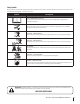
Safety Symbols This page depicts and describes safety symbols that may appear on this product. Read, understand, and follow all instructions on the machine before attempting to assemble and operate. Symbol Description READ THE OPERATOR’S MANUAL(S) Read, understand, and follow all instructions in the manual(s) before attempting to assemble and operate WARNING— ROTATING BLADES Do not put hands or feet near rotating parts or under the cutting deck. Contact with the blade(s) can amputate hands and feet.
Section 2 — Safe Operation Practices Figure 1 line Figure 2 (TOO STEEP) 15° Slope WARNING! Slopes are a major factor related to tip-over and roll-over accidents which can result in severe injury or death. Do not operate machine on slopes in excess of 15 degrees. All slopes require extra caution. Always mow across the face of slopes, never up and down slopes. To check the slope, proceed as follows: 1. Remove this page and fold along the dashed line. 2.
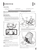
3 Assembly & Set-Up Contents of Crate • One RZT L Tractor • One Oil Drain Tube • One Deck Wash Hose Coupler • One Tractor Operator’s Manual • One Engine Operator’s Manual • One Hardware Pack NOTE: This Operator’s Manual covers several models. Tractor features may vary by model. Not all features in this manual are applicable to all tractor models and the tractor depicted may differ from yours. 2. Remove the two shoulder screws and lock nuts in the seat pan as shown in Figure 3-2.
Position Drive Control levers Connecting the Battery Cables CALIFORNIA PROPOSITION 65 WARNING! Battery posts, terminals, and related accessories contain lead and lead compounds, chemicals known to the State of California to cause cancer and reproductive harm. Wash hands after handling. The drive control levers of the tractor are lowered for shipping purposes. The hex screws and flat washers that normally secure the control levers in their operating position are in a hardware pack inside your manual bag.
Lower Deck Discharge Chute Deflector Adjusting the Seat WARNING! Never operate the mower deck without the chute deflector installed and in the down position. To adjust the position of the seat, pull up and hold the seat adjustment lever. Slide the seat forward or rearward to the desired position; then release the adjustment lever. Make sure seat is locked into position before operating the tractor. See Figure 3-8. The discharge chute deflector must be installed before operating the mower. 1.
4 Controls & Features Deck Lift Handle LH Drive RH Drive Control Lever Control Lever Seat Adjustment Lever Deck Height Index Throttle Control or Throttle/Choke Control Hour Meter/ Indicator Panel Choke Control PTO Switch Ignition Switch Fuel Level Window Fuel Tank Cap Cup Holder Storage Tray LH Transmission Bypass Rod NOTE: This Operator’s Manual covers several models. Tractor features may vary by model.
Ignition Switch Fuel Tank Cap The ignition switch is located on the RH console to the rear of the PTO switch. The ignition switch has three positions as follows: The fuel tank cap is located near the middle of the LH console. Turn the fill cap approximately 1⁄4 turn and pull upward to remove. The fuel cap is tethered to the tractor to prevent its loss. Do not attempt to remove the cap from the tractor. Fill tank to the bottom of the filler neck, allowing some space in the tank for fuel expansion.
Throttle Control (If so equipped) Indicator Panel Features The throttle control is located on the RH console to the left of the hour meter/indicator panel. When set in a given position, a uniform engine speed will be maintained. FAST Illuminates and the battery voltage is displayed briefly when the ignition switch it turned to the “ON” position. Push the throttle control handle forward to increase the engine speed.
5 Operation General Safety • • • RECEIVE INSTRUCTION — Entirely read this operator’s manual. Learn to operate this machine SAFELY. Do not risk INJURY or DEATH. Allow only those who have become competent in its usage to operate this tractor. Before starting the engine or beginning operation, be familiar with the controls. The operator should be in the operator’s seat. The PTO switch must be in the disengaged position and the RH and LH drive control levers moved fully outward in the neutral position.
Starting the Engine WARNING! This tractor is equipped with a safety interlock system designed for the protection of the operator. Do not operate the tractor if any part of the interlock system is malfunctioning. Periodically check the functions of the interlock system for proper operation. WARNING! For personal safety, the operator must be sitting in the tractor seat when starting the engine. 1.
Practice Operation (Initial Use) 3. Operating a zero-turn tractor is not like operating a conventional type riding tractor. Although and because a zero turn tractor is more maneuverable, getting used to operating the control levers takes some practice. NOTE: Although the tractor’s engine is designed to run at full throttle, when performing a practice session the tractor must be operated at less than full throttle. This only applies to practice.
Turning the Tractor While Driving Forward WARNING! When reversing the direction of travel, we recommend performing gradual ‘U’ turns where possible. Sharper turns increase the possibility of turf defacement, and could affect control of the tractor. ALWAYS slow the tractor before making sharp turns. To turn the tractor while driving forward, move the control levers as necessary so that one lever is rearward of the other. The tractor will turn in the direction of the rearward control lever. 1.
Turning While Driving Rearward Executing a Zero Turn WARNING! When executing a zero turn, the tractor To turn the tractor while driving rearward, move the control levers as necessary so that one lever is forward of the other. The tractor will turn in the direction of the forward control lever. 1. To turn to the left while traveling in reverse, move the left drive control lever forward of the right lever. See Fig. 5-7. MUST BE STOPPED.
Stopping the Tractor 1. Move both drive control levers to the neutral position to stop the motion of the tractor. 2. Push the PTO switch downward to the disengaged position. 3. Use the deck lift handle to raise the deck to its highest position. 4. If dismounting the tractor, move the drive control handles fully outward in the neutral position which also engages the parking brake, move the throttle control lever to the fast position, turn the ignition switch to stop and remove the key from the switch.
Checking the Safety Interlock Circuits Periodically check the safety interlock circuits to ensure they are working properly. If a safety circuit is not working as designed, contact you Cub Cadet dealer to have the tractor inspected. DO NOT operate the tractor if any safety circuit is not functioning properly. To check the safety circuits, proceed as follows: 1. Pull the PTO switch upward to the engaged position. Momentarily turn the ignition switch to the start position; the engine should not crank. 2.
6 Maintenance & Adjustments Maintenance Schedule Before Each use Check Engine Intake Screen/Cover Every 10 Hours Every 25 Hours Every 50 Hours Every 100 Hours Prior to Storing P Clean Battery Terminals Lube Front Wheels P P P P Clean Engine Cooling Fins Lube Front Deck Wheels NOTE: This Operator’s Manual covers several models. Tractor features may vary by model. Not all features in this manual are applicable to all tractor models and the tractor depicted may differ from yours. P P P P 3.
Tires 3. Check the tire air pressure after every 50 hours of operation or weekly. Keep the tires inflated to the recommended pressures. Improper inflation will shorten the tire service life. See the tire side wall for proper inflation pressures. Observe the following guidelines: The battery must be stored with a full charge. A discharged battery can freeze sooner than a charged battery. A fully charged battery will store longer in cold temperatures than hot. 4.
Tractor Storage Removing The Tractor From Storage If your tractor is not going to be operated for an extended period of time (thirty days to approximately six months), the tractor should be prepared for storage. Store the tractor in a dry and protected location. If stored outside, cover the tractor (including the tires) to protect it from the elements. The procedures outlined below should be performed whenever the tractor is placed in storage. 1. Check the engine oil. 2.
To adjust the drive control levers forward/rearward, proceed as follows: 4. 1. The deck is properly leveled when both blade tip measurements are equal. Retighten the hex bolt on the front left deck hanger bracket when proper adjustment is achieved. If not already loose, loosen the hex screw and rotate the control lever either forward or rearward to the desired position. See Figure 6-3. NOTE: If the control lever is too tight to move, slightly loosen the hex crew at the bottom of the control lever. 2.
Adjusting the Front Gauge Wheels Adjusting the Rear Deck Rollers (If so equipped) WARNING!: Keep hands and feet away from the discharge opening of the cutting deck. The front gauge wheels on the mower deck are an anti-scalp feature, and should not ride on the ground. The front gauge wheels should be approximately 1⁄4-1⁄2” above the ground when the deck is set in the desired height setting. The rear deck rollers can be set in either the low or high position.
Off-Season Storage Removing the Riding Mower from Storage Riding Mower Storage 1. Check the engine oil. 2. Fully charge the battery, lower riding mower off blocks, and inflate the tires to the recommended pressure. 3. Remove the spark plugs and wipe them off. Using the starter, crank the engine to pump the excess oil out of the spark plug holes. Replace the spark plugs and the ignition leads. 4. If drained before storing, fill the fuel tank with clean, fresh gasoline. 5.
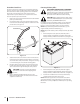
7 Service Battery Removal Charging the Battery WARNING! Battery posts, terminals and related accessories contain lead and lead compounds. Wash hands after handling. Test and, if necessary, recharge the battery after the tractor has been stored for a period of time. • The battery is located beneath the seat frame. To remove the battery: 1. Remove the hex washer screw securing the battery holddown bracket to the frame. Then flip the battery holddown bracket up to free the battery. See Figure 7-1.
Releasing Belt Tension with the Idler Pulley Rolling the Belt off the PTO Pulley 1. 1. Using the deck lift handle, raise the deck to the position that provides the most horizontal run of the belt between the deck idler pulleys and the PTO pulley on the bottom of the engine. 2. Sitting behind the tractor facing forward, reach beneath the tractor to grasp the belt at the front of the PTO pulley.
6. Pull the cotter pin out of the front deck lift rod securing it to the deck. See Figure 7-6. Slide the deck lift rod out of the front hanger bracket. Deck Installation Install the deck on the tractor as follows: 1. Place the deck lift handle in the highest mowing position See Figure 7-3. 2. Slide the deck under the tractor on the right side of the tractor lining up the deck hanger brackets and the deck lift arms.. 3.
Replacing the Belt 6. Place the belt around the idler pulleys removed in step 3 with the “V” side facing in. Once in place, reinstall all the hardware and tighten the flange lock nut to secure the assembly. See Figure 7-8. Route the belt as shown in Figure 7-8 and then reinstall the deck (refer to Deck Installation on page 30). 42” Deck 1. Remove the deck from beneath the tractor, (refer to Deck Removal on page 28). 7. 2. Remove the hex washer screws securing the belt covers to the deck.
4. Remove the belt from the spindle pulleys. 5. Install the new belt around the spindle pulleys as shown and reinstall the belt covers. See Figure 7-9. 6. Place the belt around the idler pulleys removed in step 3 with the “V” side facing in. Once in place, reinstall all the hardware and tighten the flange lock nut to secure the assembly. See Figure 7-10. 7. 3. Remove the two idler pulleys by removing the hex screws and flange lock nuts that secure them to the deck and the idler arm. See Figure 7-12.
Mower Blade Care Changing the Transmission Drive Belt WARNING! Before performing any maintenance, place the PTO switch in the “OFF” position, engage the parking brake lever, turn the ignition key to the “OFF” position and remove the key from the switch. Protect your hands by using heavy gloves when handling the blades. When servicing the mower deck, be careful not to cut yourself on the sharpened blades. The cutting blades must be kept sharp at all times.
8 Troubleshooting Problem Excessive vibration Uneven cut Mower will not mulch grass (If Equipped w/Mulching Kit) 34 Cause Remedy 1. Cutting blade loose or unbalanced. 1. Tighten blade and spindle. 2. Damaged or bent cutting blade. 2. Replace blade. 1. Deck not leveled properly. 1. Perform side-to-side deck adjustment. 2. Dull blade. 2. Sharpen or replace blade. 3. Uneven tire pressure. 3. Check tire pressure in all four tires. 1. Engine speed too low. 1.
9 Replacement Parts Component Part Number and Description 954-04033A 954-04325 954-05008 954-04329 Deck Belt, RZT L42 Deck Belt, RZT L46 Deck Belt, RZT L50 Deck Belt, RZT L54 954-04317A Drive Belt 942-04312 942-04244A 942-04053C 942-04053-X 942-05056 Deck Blade, RZT L42 Deck Blade, RZT L46 Deck Blade, RZT L50 Extreme Blade, RZT L50 Deck Blade, RZT L54 918-04822A 918-05078 918-04125B 618-06978 Deck Spindle, RZT L42 Deck Spindle, RZT L46 Deck Spindle, RZT L50 Deck Spindle, RZT L54 734-04155 Deck Wh
Component Part Number and Description 946-1085A Choke Control Cable (w/ Kawasaki) 946-05131 946-04830B Throttle Control Cable (w/ Kawasaki) Throttle/Choke Control Cable (w/ Kohler) 325-05000 Ignition Key 946-05008 Brake Cable 631-04288 631-05162 631-05176 Discharge Chute Assy., RZT L42/46 Discharge Chute Assy., RZT L50 Discharge Chute Assy., RZT L54 634-04293-0931 Wheel Assembly, RZT L42/46 634-04128-0931 Wheel Assembly, RZT L50 & RZT L54 634-04212B 634-04711 Caster Wheel Assy.
10 Attachments & Accessories The following attachments and accessories are compatible with your Cub Cadet RZT L tractor. See your Cub Cadet dealer or the retailer from which you purchased your tractor for information regarding price and availability.
FEDERAL and/or CALIFORNIA EMISSION CONTROL WARRANTY STATEMENT YOUR WARRANTY RIGHTS AND OBLIGATIONS MTD Consumer Group Inc, the United States Environmental Protection Agency (EPA), and for those products certified for sale in the state of California, the California Air Resources Board (CARB) are pleased to explain the emission (evaporative and/or exhaust) control system (ECS) warranty on your 2013 and later small off-road spark-ignited engine and equipment (outdoor equipment engine).
10. Add-on or modified parts that are not exempted by the Air Resources Board may not be used. The use of any non-exempted add-on or modified parts by the ultimate purchaser will be grounds for disallowing a warranty claims. MTD Consumer Group Inc will not be liable to warrant failures of warranted parts caused by the use of a non-exempted add-on or modified part.
CUB CADET LLC MANUFACTURER’S LIMITED WARRANTY FOR RESIDENTIAL ZERO-TURN (“RZT”) MOWERS IMPORTANT: To obtain warranty coverage owner must present an original proof of purchase and applicable maintenance records to the servicing dealer. Please see the operator’s manual for information on required maintenance and service intervals.