OPERATOR’S MANUAL RZT SERIES TRACTORS Model Numbers RZT 50 (w/50" Mower Deck) RZT 54 (w/54" Mower Deck) IMPORTANT: READ SAFETY RULES AND INSTRUCTIONS CAREFULLY Warning: This unit is equipped with an internal combustion engine and should not be used on or near any unimproved forestcovered, brush-covered or grass-covered land unless the engine’s exhaust system is equipped with a spark arrester meeting applicable local or state laws (if any).
TABLE OF CONTENTS TRACTOR PREPARATION .................................................................................................... 2 IMPORTANT SAFE OPERATION PRACTICES .................................................................... 4 SAFETY DECALS AND LABELS ........................................................................................... 7 SLOPE GAUGE ......................................................................................................................
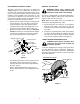
CONNECT THE BATTERY POSITION DRIVE CONTROL LEVERS The drive control levers of the tractor are lowered for shipping purposes. To accomplish this, the flange lock nut, hex screw, and flat washer normally used to secure each control lever to its pivot bracket are removed. The hardware is then installed in the slotted hole of each control lever for shipment. The control levers must be moved to their operating position.
WARNING • • • The engine exhaust, some of its constituents, and certain vehicle components contain or emit chemicals known to the State of California to cause cancer, birth defects or other reproductive harm. This unit is equipped with an internal combustion engine and should not be used on or near any unimproved forest-covered, brush-covered, or grass-covered land unless the engine’s exhaust system is equipped with a spark arrester meeting applicable local or state laws (if any).
DO: 13. Mow only in daylight or good artificial light. Mow across slopes, not up and down. 14. Do not operate the machine while under the influence of alcohol or drugs. Keep all movement on the slopes slow and gradual. Do not make sudden changes in speed or direction. Rapid acceleration or deceleration could cause the front of the machine to lift and rapidly flip over backwards, which could cause serious injury. 15. Watch for traffic when operating near or crossing roadways. 16.
8. After striking a foreign object, stop the engine, remove the wire from the spark plug and thoroughly inspect the mower for any damage. Repair the damage before restarting and operating the mower. 5. Never allow children under 14 years old to operate the machine. Children 14 years and over should only operate the machine under close parental supervision and proper instruction. 6.
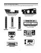
SAFETY DECALS AND LABELS Keep product safety graphics (decals) clean. Replace any safety graphic that is damaged, destroyed, missing, painted over or can no longer be read. Replacement safety graphics are available through your dealer. NOTI CE ME T E R MI N D E R Every 50 Hours of Use a “Change Oil” Message Will Flash On The Display For 2 Minutes Every Time The Tractor Is Started. Follow The Oil Change Intervals Provided In The Engine Manual. • PTO Automatically OI L BATT.
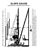
NE, R WARNING 15° N DO TTE D LI EPR ES ENT ING A 15 ° SL OPE Do not mow on inclines with a slope in excess of 15 degrees (a rise of approximately 2-1/2 feet every 10 feet). A riding mower could overturn and cause serious injury. If operating a walk-behind mower on such a slope, it is extremely difficult to maintain your footing and you could slip, resulting in serious injury. Operate RZT zero turn tractors across the face of slopes rather than up and down.
TO THE OWNER This Operator’s Manual is an important part of your new tractor. The information contained in this manual has been prepared in detail to help you better understand the features, correct operation, adjustments, and maintenance of your tractor. The performance and dependability of this tractor rely greatly on the manner in which it is operated and maintained. Therefore, it is recommended that all operators of the tractor carefully read this manual and fully understand its operation.
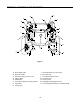
SECTION 1: CONTROLS AND FEATURES B O C C A N M D E L J F F G P K H Figure 5 A. B. C. D. E. F. G. H. Deck Height Index Deck Lift Handle RH and LH Drive Control Levers Ignition Switch PTO Switch Transmission Bypass Rod (Not Shown) Cup Holder Storage Tray J. K. L. M. N. O. P. 10 Seat Adjustment Lever (Not Seen) Fuel Tank Cap Hour Meter /Indicator Panel Throttle Control Choke Control Parking Brake Engagement Lever Trans.
NOTE: References to LEFT, RIGHT, FRONT, and E. Power Take-Off (PTO) Switch REAR indicate that position on the tractor when facing forward while seated in the operator’s seat. The PTO switch is located on the RH console to the right of the operator’s seat. A. Deck Height Index The deck height index consists of six index notches located on the front/right of the seat box frame.
check the battery and charging system for possible causes and/or contact your Cub Cadet dealer. WARNING: Never fill the fuel tank when the engine is running. If the engine is hot from recently running, allow to cool for several minutes before refueling. Highly flammable gasoline could splash onto the engine and cause a fire. Oil Pressure Indicator (Refer to Figure 8) • This warning lamp indicates low engine oil pressure.
P. MODEL RZT 54 ONLY - Transmission Oil Expansion Reservoir The transmission oil expansion reservoir is connected by hoses to the RH and LH transmission assemblies, and is located beneath the seat box. The function of the reservoir is to hold the natural expansion of transmission oil that occurs as the transmission warms up during operation. DO NOT FILL THE RESERVOIR. N. Choke Control The choke knob controls the position of the engine choke.
• This engine is certified to operate only on clean, fresh, unleaded regular gasoline. For best results, fill the fuel tank with only clean, fresh, unleaded gasoline with a pump sticker octane rating of 87 or higher. • Unleaded gasoline is recommended because it leaves less combustion chamber deposits and reduces harmful exhaust emissions. Leaded gasoline is not recommended and must not be used where exhaust emissions are regulated.
disconnect the jumper cables in the exact reverse order of their connection. engine does not start within this time, turn the key to “OFF” and wait at least 15 seconds to allow the engine’s starter motor to cool. Try again after waiting. If after a few attempts the engine fails to start, do not keep trying to start it with the choke closed as this will cause flooding and make starting more difficult.
• • Adjust the operator’s seat to the most comfortable position that allows you to operate the controls. See seat adjustment in the ADJUSTMENTS section. • Release the parking brake. • Move the RH and LH drive control levers inward in the neutral position. Refer to Figure 11. As the control levers are pushed farther forward the speed of the tractor will increase.
IMPORTANT: Always maintain your grasp on the drive control levers. Do not release the levers to slow the tractor or to return to neutral. - To turn to the right, move the right drive control lever rearward of the left lever. See Figure 14. FORWARD RIGHT TURN Turning While Driving Rearward • To turn the tractor while driving rearward, move the control levers as necessary so that one lever is forward of the other. The tractor will turn in the direction of the forward control lever.
STOPPING THE TRACTOR Executing a Zero Turn WARNING: When executing a zero turn, the tractor MUST BE STOPPED. Executing a zero turn while the tractor is moving can significantly reduce your control of the tractor and will cause severe turf defacement to occur. • Move both drive control levers to the neutral position to stop the motion of the tractor. • Push the PTO switch disengaged position. • Use the deck lift handle to raise the deck to its highest position.
IMPORTANT: When stopping the tractor for any reason while on a grass surface, always: • Place the shift lever in neutral, • Engage the parking brake, • Shut engine off and remove the key. USING THE MOWER DECK WARNING: Make certain the area to be mowed is free of debris, sticks, stones, wire or other objects that can be thrown by the rotating blades. Doing so will minimize the possibility of having your lawn ‘‘browned’’ by hot exhaust from your tractor’s running engine.
SECTION 3: ADJUSTMENTS ADJUSTING THE OPERATORS SEAT • To adjust the position of the seat, move and hold the seat adjustment lever toward the left. Slide the seat forward or rearward to the desired position; then release the adjustment lever. Make sure seat is locked into position before operating the tractor. See Figure 20. Seat • Reposition the control lever to align with the other set of holes in the pivot bracket and insert the shoulder screw removed earlier.
SECTION 4: MAINTENANCE ENGINE MAINTENANCE Engine maintenance procedures and schedules can be found in the copy of the engine manual found at the end of this manual. Follow those schedules for performing engine maintenance. Model RZT 54 ONLY The model RZT54 is equipped with a transmission oil expansion reservoir. Under normal operating conditions, the oil level in the expansion reservoir does not need to be checked and no additional oil is needed.
• • • CHARGING THE BATTERY Test and, if necessary, recharge the battery after the tractor has been stored for a period of time. • A voltmeter or load tester should read 12.6 volts (DC) or higher across the battery terminals. • Charge the battery with a 12-volt battery charger at a MAXIMUM rate of 10 amps. Keep all sources of ignition (cigarettes, matches, lighters) away from the battery. The gas generated during charging can be combustible.
If you have a recurring problem with blown fuses, have the tractor’s electrical system checked by your Cub Cadet dealer. • Relays and Switches There are several safety switches in the electrical system. If a function of the safety interlock system described earlier is not functioning properly, have the electrical system checked by your Cub Cadet dealer.
• • • • If the rotation stops, adjust the ferrule up or down the control rod as necessary to align with the hole in the transmission control arm. Re-insert the ferrule into the hole in the control arm and secure with the internal cotter pin. If necessary, repeat the previous two steps to adjust the other transmission control rod. Lower the tractor and remove the jack. Tighten the jam nut against the console and reposition the control lever if necessary.
Emptying the fuel system: • Prior to putting the tractor in storage, monitor fuel consumption with the goal of running the fuel tank empty. TRACTOR STORAGE If your tractor is not going to be operated for an extended period of time (thirty days to approximately six months), the tractor should be prepared for storage. Store the tractor in a dry and protected location. If stored outside, cover the tractor (including the tires) to protect it from the elements.
SECTION 5: MOWER DECK Rolling the belt off the PTO pulley. • Using the deck lift handle, raise the deck to the position that provides the most horizontal run of the belt between the deck idler pulleys and the PTO pulley on the bottom of the engine. This section contains removal, installation, adjustment, and maintenance information for the mower deck. Some of the following information applies only to the model RZT50 deck, while some applies only to the RZT54.
8. Using care to prevent the front hanger rod from falling back into the deck bracket slots, carefully slide the cutting deck (from the right side) out from underneath the tractor. • Install the belt in the PTO pulley on the bottom of the engine. • Route the backside of the belt around the fixed idler pulley of the deck. Refer to Figure 30.
Front to Back Leveling. The front of the deck should be approximately 1/4 inch lower than the rear of the deck. Adjust if necessary as follows: • With the deck raised off of the ground, rotate the outer blades so that they are parallel to the frame of the tractor. • If the side to side leveling was done correctly, measuring just the right blade should be acceptable to attain the correct back to front pitch of the deck.
Using the lift handle, set the deck in the desired height setting, then check the gauge wheel distance from the ground below. If necessary adjust the front gauge wheels as follows: • Visually check the distance between the front gauge wheels and the ground. If the gauge wheels are near or touching the ground, they should be raised. If more than 1/2" above the ground, they should be lowered. • Remove the lock nut securing one of the front gauge wheel shoulder screws to the deck.
WARNING: When servicing the mower deck, be careful not to cut yourself on the sharpened blades. DECK MAINTENANCE Using the Deck Wash System WARNING: When using the deck wash system, never engage the deck from any position other than the operator’s seat of the tractor. Do not use an assistant or engage deck in the presence of any bystanders. • • • The cutting blades must be kept sharp at all times.
REPLACING THE DECK DRIVE BELT • • Remove the deck from beneath the tractor, (refer to Deck Removal on page 26). • Install the new belt around the spindle pulleys as shown in Figure 39 and reinstall the belt covers. • Route the belt rearward between the two idler pulleys and reinstall the deck following the instructions in Deck Installation on page 27. Remove the hex tapping screws securing the belt covers to the deck and remove the belt from the spindle pulleys. Refer to Figure 39.
ENGINE MANUAL A Kawasaki engine is used on this RZT tractor model. The following section is a reproduction of the Kawasaki engine manual that applies to the RZT50 and RZT54 engines. The RZT50 use the model FH661, and the RZT54 uses the model FH721V engine. Read this manual in its entirety. Observe all warnings and follow all applicable operation and maintenance instructions provided in the manual.
KAWASAKI LIMITED WARRANTY CALIFORNIA AND FEDERAL EMISSIONS CONTROL SYSTEMS SMALL OFF-ROAD ENGINES The California Air Resources Board, the Environmental Protection Agency (EPA) , and Kawasaki Motors Corp., U.S.A. (hereinafter “Kawasaki”) are pleased to explain the Emission Control Systems Warranty on your Kawasaki small off-road engine. In California and other states, new small off-road engines must be designed, built and equipped to meet the stringent anti-smog standards.
3. LIMITED LIABILITY. (a) The liability of Kawasaki under this Emission Control Systems Warranty is limited solely to the remedying of defects in materials or workmanship by any authorized Kawasaki small off-road engine dealer at its place of business during customary business hours. This warranty does not cover inconvenience or loss of use of the small off-road engine or transportation of the small off-road engine to or from the Kawasaki dealer.
CALIFORNIA EMISSION CONTROL WARRANTY STAT EMENT YOUR W ARRANTY RIGHTS AND OBLIGATIONS The California Air Resources Board and MTD Consumer Group Inc. are pleased to explain the evaporative emission control system warranty on your 2007 lawn mower. In California, new lawn mower must be designed, built and equipped to meet the State’s stringent anti-smog standards. MTD Consumer Group Inc.
CUB CADET LLC MANUFACTURER’S LIMITED WARRANTY FOR RESIDENTIAL ZERO-TURN (“RZT”) MOWERS important: To obtain warranty coverage owner must present an original proof of purchase and applicable maintenance records to the servicing dealer. Please see the operator’s manual for information on required maintenance and service intervals.