OPERATOR’S MANUAL RZT SERIES TRACTOR Model Number RZT 50 w/50" Mower Deck IMPORTANT: READ SAFETY RULES AND INSTRUCTIONS CAREFULLY Warning: This unit is equipped with an internal combustion engine and should not be used on or near any unimproved forestcovered, brush-covered or grass-covered land unless the engine’s exhaust system is equipped with a spark arrester meeting applicable local or state laws (if any). If a spark arrester is used, it should be maintained in effective working order by the operator.
TABLE OF CONTENTS TRACTOR PREPARATION .................................................................................................... 2 IMPORTANT SAFE OPERATION PRACTICES .................................................................... 4 SAFETY DECALS AND LABELS ........................................................................................... 7 SLOPE GAUGE ......................................................................................................................
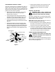
POSITION DRIVE CONTROL LEVERS • The drive control levers are unfastened from their respective pivot brackets and lowered for shipping purposes. The control levers must be repositioned and secured to the pivot bracket to operate the tractor. Reposition the control levers as follows: CONNECT THE BATTERY • Remove the nut knob, bell washer, and carriage bolt from either of the two control lever pivot brackets. Refer to Figure 2.
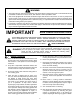
WARNING • • • The engine exhaust, some of its constituents, and certain vehicle components contain or emit chemicals known to the State of California to cause cancer, birth defects or other reproductive harm. This unit is equipped with an internal combustion engine and should not be used on or near any unimproved forest-covered, brush-covered, or grass-covered land unless the engine’s exhaust system is equipped with a spark arrester meeting applicable local or state laws (if any).
13. Mow only in daylight or good artificial light. DO: Mow across slopes, not up and down. 14. Do not operate the machine while under the influence of alcohol or drugs. Keep all movement on the slopes slow and gradual. Do not make sudden changes in speed or direction. Rapid acceleration or deceleration could cause the front of the machine to lift and rapidly flip over backwards, which could cause serious injury. 15. Watch for traffic when operating near or crossing roadways. 16.
8. After striking a foreign object, stop the engine, remove the wire from the spark plug and thoroughly inspect the mower for any damage. Repair the damage before restarting and operating the mower. 5. Never allow children under 14 years old to operate the machine. Children 14 years and over should only operate the machine under close parental supervision and proper instruction. 6.
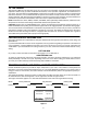
SAFETY DECALS AND LABELS Keep product safety graphics (decals) clean. Replace any safety graphic that is damaged, destroyed, missing, painted over or can no longer be read. Replacement safety graphics are available through your dealer. NOTI CE BATT.OIL • PTO Automatically START Disengages When START FORWARD HOURS 1/10 REVERSE REV ERSE FO R W A R D NEUTRAL PT O/ P ARK BLADE BRAKE Both Lap Bars Are Moved Into Reverse.
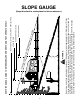
NE, R WARNING 15° N DO TTE D LI EPR ES ENT ING A 15 ° SL OPE Do not mow on inclines with a slope in excess of 15 degrees (a rise of approximately 2-1/2 feet every 10 feet). A riding mower could overturn and cause serious injury. If operating a walk-behind mower on such a slope, it is extremely difficult to maintain your footing and you could slip, resulting in serious injury. Operate RZT zero turn tractors across the face of slopes rather than up and down.
TO THE OWNER This Operator’s Manual is an important part of your new tractor. The information contained in this manual has been prepared in detail to help you better understand the features, correct operation, adjustments, and maintenance of your tractor. The performance and dependability of this tractor rely greatly on the manner in which it is operated and maintained. Therefore, it is recommended that all operators of the tractor carefully read this manual and fully understand its operation.
SECTION 1: CONTROLS AND FEATURES B O C A C N M D E L J F F G K H Figure 4 A. B. C. D. E. F. G. Deck Height Index Deck Lift Handle RH and LH Drive Control Levers Ignition Switch PTO Switch Transmission Bypass Rod (Not Shown) Cup Holder H. J. K. L. M. N. O.
NOTE: References to LEFT, RIGHT, FRONT, and E. Power Take-Off (PTO) Switch REAR indicate that position on the tractor when facing forward while seated in the operator’s seat. The PTO switch is located on the RH console to the right of the operator’s seat. A. Deck Height Index The deck height index consists of six index notches located on the front/right of the seat box frame.
WARNING: Never fill the fuel tank when the engine is running. If the engine is hot from recently running, allow to cool for several minutes before refueling. Highly flammable gasoline could splash onto the engine and cause a fire. Oil Pressure Indicator (Refer to Figure 7) • L. Hour Meter/Indicator Panel The hour meter/indicator panel is located on the LH console to the left of the operator’s seat.
N. Choke Control The choke knob controls the position of the engine choke. Pull the knob out to choke the engine; push the knob in to open the choke. O. Parking Brake Engagement Lever The parking brake engagement lever is located on the front/left of the seat box frame, and is used to engage the parking brake. • Pull the lever fully upward and to the left; then lower into the "J" slot to engage the parking brake.
• Gasohol (up to 10% ethyl alcohol, 90% unleaded gasoline by volume) is an approved fuel. Other gasoline/alcohol blends are not approved. • Methyl Tertiary Butyl Ether (MTBE) and unleaded gasoline blends (up to a maximum of 15% MTBE by volume) are approved fuels. Other gasoline/ ether blends are not approved. • Move the RH and LH drive control levers fully outward in the neutral position. Refer to Figure 9. • Operator must be sitting in the tractor seat. • Check the engine oil level.
• Observe the hour meter/indicator panel. If the battery indicator light or oil pressure light come on, immediately stop the engine. Have the tractor inspected by your Cub Cadet dealer. COLD WEATHER STARTING • When starting the engine at temperatures near or below freezing, ensure the correct viscosity motor oil is used in the engine and the battery is fully charged. Start the engine as follows: • Use fresh winter grade fuel. Winter grade gasoline has higher volatility to improve starting.
• Move the RH and LH drive control levers inward in the neutral position. Refer to Figure 10. DRIVING FORWARD Faster Control Lever Moved Inward and in Neutral Slower Neutral Position Figure 11 Figure 10 • NOTE: If the control levers are not even in the neutral position, refer to Section 3 and adjust the levers so that they are even. • IMPORTANT: Always maintain your grasp on the drive control levers. Do not release the levers to slow the tractor or to return to neutral.
- To turn to the right, move the right drive control lever rearward of the left lever. See Figure 13. IMPORTANT: Always maintain your grasp on the drive control levers. Do not release the levers to slow the tractor or to return to neutral. FORWARD RIGHT TURN Turning While Driving Rearward • To turn the tractor while driving rearward, move the control levers as necessary so that one lever is forward of the other. The tractor will turn in the direction of the forward control lever.
Executing a Zero Turn STOPPING THE TRACTOR WARNING: When executing a zero turn, the tractor MUST BE STOPPED. Executing a zero turn while the tractor is moving can significantly reduce your control of the tractor and will cause severe turf defacement to occur. • Move both drive control levers to the neutral position to stop the motion of the tractor. • Push the PTO switch disengaged position. • Use the deck lift handle to raise the deck to its highest position.
USING THE MOWER DECK IMPORTANT: When stopping the tractor for any reason while on a grass surface, always: • Place the shift lever in neutral, • Engage the parking brake, • Shut engine off and remove the key. WARNING: Make certain the area to be mowed is free of debris, sticks, stones, wire or other objects that can be thrown by the rotating blades. Doing so will minimize the possibility of having your lawn ‘‘browned’’ by hot exhaust from your tractor’s running engine.
SECTION 3: ADJUSTMENTS ADJUSTING THE OPERATORS SEAT • To adjust the position of the seat, move and hold the seat adjustment lever toward the left. Slide the seat forward or rearward to the desired position; then release the adjustment lever. Make sure seat is locked into position before operating the tractor. See Figure 19. • Insert the carriage bolt through the pivot bracket and control lever slot. Slide the bell washer onto the bolt and screw on the nut knob, but do not fully tighten now.
SECTION 4: MAINTENANCE ENGINE MAINTENANCE GENERAL BATTERY INFORMATION Engine maintenance procedures and schedules can be found in the engine manual that was packed with this manual. Follow those schedules for performing engine maintenance. WARNING: • Battery posts, terminals and related accessories contain lead and lead compounds. Wash hands after handling. • Should battery acid accidentally splatter into the eyes or onto the skin, rinse the affected area immediately with clean cold water.
• • Remove the hex cap screw and sems nut securing the red positive battery lead to the positive battery post (marked POS). Carefully lift the battery out of the tractor. BATTERY STORAGE Install the battery by repeating the above steps in the reverse order. WARNING: Always connect the positive lead to the battery before connecting the negative lead. This will prevent sparking or possible injury from an electrical short caused by contacting the tractor body with tools being used to connect the cables.
TIRE MAINTENANCE IMPORTANT: The tractor will not drive with the bypass rods in the engage position. Check the tire air pressure after every 50 hours of operation or weekly. Keep the tires inflated to the recommended pressures. Improper inflation will shorten the service life of a tire. See the tire side wall for proper inflation pressures. Observe the following guidelines: • Do not inflate a tire above the maximum pressure shown on the sidewall of the tire.
TRACTOR HIGH SPEED TRACKING TRANSMISSION DRIVE BELT If the tractor tracks to one side with both drive control levers fully forward, adjust the control levers as follows: If the transmission drive belt becomes worn and causes the drive transmissions to slip, the drive belt must be replaced. To replace the drive belt, proceed as follows: • • Check for proper and balanced air pressure in both front and rear tires. Refill tires if necessary.
TRACTOR STORAGE Emptying the fuel system: • Prior to putting the tractor in storage, monitor fuel consumption with the goal of running the fuel tank empty. If your tractor is not going to be operated for an extended period of time (thirty days to approximately six months), the tractor should be prepared for storage. Store the tractor in a dry and protected location. If stored outside, cover the tractor (including the tires) to protect it from the elements.
SECTION 5: MOWER DECK This section contains removal, installation, adjustment, and maintenance information for the 50-inch mower deck. Instructions for installation and removal of the optional mulching plug are located at the end of this section. Rolling the belt off the PTO pulley. • DECK REMOVAL WARNING: The muffler at the rear of the tractor may be extremely hot, and could cause serious burns. Use extreme caution when near the muffler, or allow the muffler to fully cool before removing the belt.
7. Slide the deck forward so that the deck front hanger rod can be lifted out of the two slots of the front deck bracket. After lifting the front hanger rod out of the slots, slide the deck rearward so that the rod can no longer engage the slots. 8. Using care to prevent the front hanger rod from falling back into the deck bracket slots, carefully slide the cutting deck (from the right side) out from underneath the tractor. • Route the backside of the belt around the fixed idler pulley of the deck.
LEVELING THE MOWER DECK When leveled correctly the mower deck should be level side to side, and should be approximately a 1/8 to 1/4 inch lower in the front of the deck. Side to Side Leveling If the cutting deck appears to be mowing unevenly, a side to side adjustment can be performed.
ADJUSTING THE GAUGE WHEELS DECK MAINTENANCE The cutting height of the mower deck can be set in any of six height settings using the deck lift handle of the tractor. The deck heights range from 1-1/2 inches to 4 inches. The deck gauge wheel position should be approximately 1/4 to 1/2 inch above the ground when the deck is set in the desired height setting.
Mower Blade Care WARNING: Before performing any maintenance, place the PTO switch in the “OFF” position, engage the parking brake lever, turn the ignition key to the “OFF” position and remove the key from the switch. When servicing the mower deck, be careful not to cut yourself on the sharpened blades. Hex Nut The cutting blades must be kept sharp at all times. Sharpen the cutting edges of the blades evenly so that the blades remain balanced and the same angle of sharpness is maintained.
CUB CADET LLC MANUFACTURER’S LIMITED WARRANTY FOR RESIDENTIAL ZERO-TURN (“RZT”) MOWERS IMPORTANT: To obtain warranty coverage owner must present an original proof of purchase and applicable maintenance records to the servicing dealer. Please see the operator’s manual for information on required maintenance and service intervals. Without limiting the foregoing, this limited warranty does not provide coverage in the following cases: a.