Service Manual RZT Zero Turn Rider NOTE: These materials are prepared for use by trained technicians who are experienced in the service and repair of equipment of the kind described in this publication, and are not intended for use by untrained or inexperienced individuals. Such individuals should seek the assistance of an authorized service technician or dealer. Read, understand, and follow all directions when working on this equipment.
TABLE OF CONTENTS Cub Cadet RZT Deck Leveling ............................................................................................................... 1 PTO / Deck Belt Replacement ...................................................................................... 2 Deck Removal ............................................................................................................... 2 Drive Belt Replacement .....................................................................................
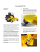
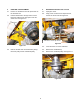
Cub Cadet RZT 22 617AA5A7P710 1. DECK LEVELING 1D224G20073 1.1. To adjust the deck pitch, front to back, loosen or tighten the jam nuts located on the front stabilizer bracket using a 15/16” socket and a 15/16” wrench. The correct deck pitch should be 1/8” to 1/4” lower in the front than in the back, as measured from the blade tips. See Figure 1.1. Front deck hanger bracket 2004 is the first year for the RZT. There are two models RZT17 and RZT22.
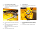
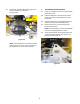
2. PTO / DECK BELT REPLACEMENT 3. DECK REMOVAL 2.1. Insert a 1/2” breaker bar into the square hole in the tensioner arm located on top of the deck. See Figure 2.1. 3.1. Release the deck J pins from the rear hanger arms. See Figure 3.1. Deck hanger rod Idler arm 1/2” Breaker bar Deck adjustment gear Figure 3.1 Figure 2.1 2.2. Pivot the tensioner arm and pulley to slacken the belt. 2.3. Remove the belt from the two stationary idler pulleys and spindle pulleys.
4. DRIVE BELT REPLACEMENT 5. SERVICING ELECTRIC PTO CLUTCH 4.1. Insert a 1/2” breaker bar into the square hole on the tensioner arm. 5.1. Unplug the clutch. 5.2. 4.2. Pull the breaker bar to the right until it can be braced in position at the pivot point of the tensioner arm. See Figure 4.2. Using a 9/16” socket and an impact wrench, remove the clutch bolt. See Figure 5.2. Idler arm 7/16-20 x 4.0 Hex cap screw Figure 5.2 Figure 4.2 4.3.
5.6. Use a 9/16” socket to adjust the air gap on the clutch to between.010” and.015”. See Figure 5.6. 6. TRANSMISSION REPLACEMENT 6.1. Insert a 1/2” breaker bar into the square hole on the tensioner arm. 6.2. Pull the breaker bar to the right until it can be braced in position at the pivot point of the tensioner arm. 6.3. Remove the belt from the transmission pulleys, tensioner pulley and the crankshaft pulley. 6.4. Remove the four lug nuts securing the rear wheel to the axle hub. .
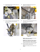
6.6. Mark the lap bar control rod threads near the clevis pin. See Figure 6.6. 6.8. Lap bar control rod Disconnect the brake return spring from the brake arm. See Figure 6.8. Brake rod Brake arm Ferrule Figure 6.6 6.7. Figure 6.8 Remove the hairpin securing the lap bar control rod to the transmission return assembly. See Figure 6.7. 6.9. Remove the bolt securing the brake arm to the transmission using a 7/16” socket. See Figure 6.9. Hair pin Note proper installation Figure 6.9 Figure 6.
6.11. Remove the front transmission mounting bolt using a 1/2” wrench and a 1/2” socket. 7. STEERING LINKAGE: ADJUSTMENT 7.1. Begin to adjust the steering by confirming that both EZTs are correctly adjusted for neutral control. See Figure 7.1. NOTE: Secure the transmission or use another technician to support the transmission while performing the next step. 6.12. Remove both transmission mounting bolts securing the transmission to the mounting bracket using two 1/2” wrenches. See Figure 6.12.
dure counts on the neutral control being correctly adjusted. 7.4. 7.5. 7.7. Start the engine. With the control rods disconnected, the EZT should self-center to neutral. The wheels should not rotate. If either wheel rotates, the neutral return assembly on the EZT that drives that wheel needs to be adjusted. Align the post on the ferrule with the hole that it seats into on the neutral return assembly.
7.11. The socket head cap screws that secure the neutral return assemblies to the EZTs act as a travel stop at the EZT end of the linkage. The lap bar pivot brackets should contact the stop screws before the socket head cap screw contacts the end of the slot on the neutral bracket. See Figure 7.11. NOTE: With one lap bar in the reverse position, and the PTO turned on, the PTO clutch should turn off as soon as the second lap bar crosses the threshold from neutral into reverse. Repeat test for each side.
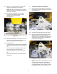
8. PIVOT BAR 8.1. Safely lift and support the front of unit. 8.2. Disconnect the - (negative) lead to the battery. 8.3. Using two 9/16” wrenches remove wheel assembly from caster bracket. See Figure 8.3. 8.5. Lightly grease the wheel spacers during re assembly. Using a grease gun fill the rest of the cavity AFTER the wheel assembly has been mounted. 8.6. Remove both caster wheel assemblies using a 9/16” wrench. See Figure 8.6. Grease fitting Caster wheel bracket Figure 8.3 Figure 8.6 8.7.
8.8. 8.9. Using a grease gun, fill the rest of the cavity AFTER final assembly. Filling before final assembly will allow the flange bearings to be pushed out. 9. SEAT REMOVAL 9.1. Disconnect the - (negative) lead to the battery. 9.2. Flip the seat forward. Keep one hand on back of seat to prevent seat from trying to bite back. See Figure 9.2. Remove both hex cap screws securing the axle shaft to the frame. This will be done with a 3/4” wrench. See Figure 8.9. 1/2-13 x 1.
9.5. 10. Disconnect wires from the seat safety switch. See Figure 9.5. CONSOLE REMOVAL The console needs to be removed to do many of the following procedures. Removing the right and left console are very similar. Under or attached to the left side console there is the neutral switch, starter solenoid, three relays, 20 amp fuse, choke knob (if applicable), hour meter, throttle lever and reverse safety switch.
10.5. The two other screws are located under the console mounting bracket. See Figure 10.5. 10.1. Disconnect the - (negative) lead to the battery. 10.2. Using a 1/2” wrench, remove the three screws securing the console to the seat frame. See Figure 10.2. #12-16 x .500 screws 5/16-18 x .625 screws Figure 10.
10.9. If any electrical connections are present disconnect or remove switch from console. See Figure 10.9. Relays PTO switch Key switch 11. BATTERY REMOVAL The battery can be removed two different ways. Depending on the final out come of the work that needs to be preformed is which technique you will use. Reverse switch When just replacing a battery the fuel pump needs to be removed.
12. 11.9. Remove right side console as per “CONSOLE REMOVAL” of this manual. FUEL TANK REMOVAL 12.1. Perform the “SEAT REMOVAL” section of this manual. 11.10. With the right side console removed the battery will slip out the side easily. See Figure 11.10. 12.2. Remove the battery per “BATTERY REMOVAL” section. NOTE: The right side console does NOT need to be removed. 12.3. Remove the two screws securing the fuel tank mounting wire to the frame using a 1/2” socket. See Figure 12.3.
12.6. Remove the left console as described in the “CONSOLE REMOVAL” section of this manual. 13. CONTROL SHAFT REPLACEMENT 13.1. Disconnect the - (negative) lead to the battery. 12.7. Rotate tank upward and slide out toward the side. See Figure 12.7. 13.2. Remove appropriate side console. refer to “CONSOLE REMOVAL” section of this manual. Fuel tank 13.3. Disconnect the ferrule from the return to neutral assembly. See Figure 13.3. Control arm Figure 12.7 12.8.
13.9. The control shaft can be removed from underneath the seat frame box. See Figure 13.9. 13.6. While rotating the control hub forward the lapbar control rod can be disconnected and removed. See Figure 13.6. Control shaft Hair pins Lap bar control rod Brake switch Figure 13.9 Figure 13.6 13.10. Inspect hex flange bearing and control shaft. Replace as needed. 13.7. Pull the control hub off the control shaft. See Figure 13.7.
14. DECK LIFT SHAFT REPLACEMENT 14.5. Carefully lift the fuel tank and remove the hex head cap screw under the rear of the fuel tank securing the seat box frame to the frame. Using a 1/2 “wrench will help immensely 14.1. The following section of this manual need to be accomplished: DECK REMOVAL NOTE: The fuel tank does NOT need to be taken out. SEAT REMOVAL 14.6. Using the same 1/2” wrench remove the other eight screws hold down the seat box frame.
14.10. Remove the only large hairpin going through the center of the deck lift shaft on the left side of the shaft. See Figure 14.10. 14.8. Using two 9/16” wrenches remove the bolt, nut, and spring on the brake handle on the left handle side of the deck lift shaft. See Figure 14.8. Deck lift shaft Brake handle Large hairpin Figure 14.8 Figure 14.10 NOTE: By removing this hairpin it will allow the concentric brake cross shaft to slide to the right to disconnecting the brake rods.
14.14. Carefully release the tension on the deck lift handle torsion spring. See Figure 14.14. 14.17. Place a piece of 2 x 4 or something equivalent under the front, left side of the seat box frame. This will allow enough clearance for deck lift assembly to slip out the back easily. See Figure 14.17. Torsion spring 2 x 4 or equivalent Figure 14.14 NOTE: Putting the deck lift handle in the lowest cutting position will make this task much easier. Figure 14.17 14.15.
15. 15.2. The PARKING BRAKE SWITCH is located under the seat box frame. See Figure 15.2. ELECTRICAL SYSTEM COMPONENTS This section is intended to help technicians identify the location and function of specific components on the RZT electrical system. -Both sets of contacts are normally open (N.O.). -When the switch is activated the red wire supplies power to the seat switch. The red/white wire is for an indicator light on the hour meter. An orange wire goes to the starter solenoid.
15.3. The NEUTRAL SWITCHES are in the console on each side of the unit. They are normally open/ normally closed switches. See Figure 15.3. 15.4. The REVERSE SWITCHES are located just under the lapbars in the console. See Figure 15.4. -The two inner terminals are N.C. They have a yellow/ white wire which supply a ground to center set of spades on the PTO switch and spade 87 on the brake relay. -There are two of these switches. -These are normally closed switches (N.C.).
15.6. The KEY SWITCH is located on right console in front of the PTO switch. 15.5. The PTO switch is located on the right console behind the key switch. This switch is part of the start circuit, PTO run circuit, and reverse safety circuit. See Figure 15.5. -There was a midyear change to the key switch. Units with serial number before 1F014G20062 should have key switch 725-04019 (Delta switch number 6900-31P) and Harness 725-04170.
-The BRAKE RELAY should have a consistent ground (terminal 86) and will receive power (terminal 85) when the brake switch is activated. Brake relay Seat relay PTO relay Figure 15.7 15.7. There are three RELAYS in the electrical system of the RZT. They are located under the right side console toward the rear. See Figure 15.7. 15.8. The STARTER SOLENOID is located under the right console just to the right of the relays. See Figure 15.8.
Starter solenoid Figure 15.
25
26