Safe Operation Practices • Set-Up • Operation • Maintenance • Service • Troubleshooting • Warranty Operator’s Manual Rear Tine Tiller — Model RT 35 WARNING READ AND FOLLOW ALL SAFETY RULES AND INSTRUCTIONS IN THIS MANUAL BEFORE ATTEMPTING TO OPERATE THIS MACHINE. FAILURE TO COMPLY WITH THESE INSTRUCTIONS MAY RESULT IN PERSONAL INJURY. CUB CADET LLC, P.O. BOX 361131 CLEVELAND, OHIO 44136-0019 Printed In USA Form No.
1 To The Owner Thank You Thank you for purchasing a Cub Cadet Garden Tiller. It was carefully engineered to provide excellent performance when properly operated and maintained. If applicable, the power testing information used to establish the power rating of the engine equipped on this machine can be found at www.opei.org or the engine manufacturer’s web site. Please read this entire manual prior to operating the equipment.
2 Important Safe Operation Practices WARNING! This symbol points out important safety instructions which, if not followed, could endanger the personal safety and/or property of yourself and others. Read and follow all instructions in this manual before attempting to operate this machine. Failure to comply with these instructions may result in personal injury. When you see this symbol.
c. When practical, remove gas-powered equipment from the truck or trailer and refuel it on the ground. If this is not possible, then refuel such equipment on a trailer with a portable container, rather than from a gasoline dispenser nozzle. 11. After striking a foreign object, stop the engine, disconnect the spark plug wire and ground against the engine. Thoroughly inspect the machine for any damage. Repair the damage before starting and operating. d.
9. If the fuel tank has to be drained, do this outdoors. 10. Observe proper disposal laws and regulations for gas, oil, etc. to protect the environment. 11. According to the Consumer Products Safety Commission (CPSC) and the U.S. Environmental Protection Agency (EPA), this product has an Average Useful Life of seven (7) years, or 130 hours of operation.
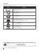
Safety Symbols This page depicts and describes safety symbols that may appear on this product. Read, understand, and follow all instructions on the machine before attempting to assemble and operate. Symbol Description READ THE OPERATOR’S MANUAL(S) Read, understand, and follow all instructions in the manual(s) before attempting to assemble and operate WARNING— ROTATING TINES Do not put hands or feet near rotating parts. Contact with the rotating parts can amputate hands and feet.
3 Assembly & Set-Up Contents of Carton • One Tiller • One Handlebar Assembly • One Engine Operator’s Manual • One Handle Crank w/ Lock Nut NOTE: This Operator’s Manual covers several models. Garden Tiller features may vary by model. Not all features in this manual are applicable to all garden tiller models and the garden tiller depicted may differ from yours. 2. NOTE: All references to the right or left side of the tiller are from the operator’s position.
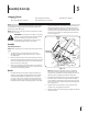
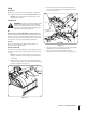
Attaching the Cable 4. To attach the cables, follow these steps: 1. Clip the cable into the cable guide located on the handle assembly panel as seen in Figure 3-3. Route the cable along the handle assembly on the righthand side. See Figure 3-2. Forward Drive Cable Cable Mount Clutch Bail Figure 3-3 Move Tiller Off Crate Figure 3-2 2. Connect the forward drive cable to the clutch bail by feeding the z-hook through the hole on the clutch bail from the outside towards the inside. See Figure 3-2. 3.
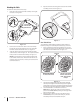
Set-Up 2. Tire Pressure Remove the oil fill plug from the transmission housing cover and locate the main drive shaft situated inside the housing. See Figure 3-6. Check the air pressure with a tire gauge. Deflate or inflate the tires equally to between 15 and 20 PSI. DO NOT EXCEED 20 P.S.I. NOTE: Be sure that both tires are inflated equally or the tiller will pull to one side. Gas & Oil Fill Up WARNING! Use extreme care when handling gasoline.
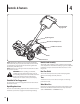
4 Controls & Features Clutch Bail & Tine Engagement Depth Regulator Handle Crank Adjustment Rear Tine Shield Tines Wheel Drive Pin NOTE: This Operator’s Manual covers several models. Garden tiller features may vary by model. Not all features in this manual are applicable to all garden tiller models and the garden tiller depicted may differ from yours. NOTE: All references to the right or left side of the tiller are from the operator’s position.
5 Operation WARNING: Before operating your machine, carefully read and understand this manual and all of its safety, operating and maintenance sections and instructions, along with all of the decals on the machine. Failure to follow these instructions can result in serious personal injury. Introduction Read this Operation Section and the Engine Operator’s Manual before you start the engine. Then, take the time to familiarize yourself with the basic operation of the tiller before using it in the garden.
To Engage Drive & Tines Adjusting the Handle Height 1. For forward motion of the wheels and power to the tines pull the Forward Clutch Bail up against the handlebar. Release the bail to stop the forward motion of wheels and tines. 2. When tilling, relax and let the wheels pull the machine while the tines dig. Walk behind and a little to one side of the tiller. Use one hand, yet keep a light — but secure — grip on the handlebar while keeping your arm loose.
• When cultivating (breaking up the surface soil around the plants to destroy weeds, see Figure 5-3), adjust the tines to dig only 1” to 2” deep. Using the shallow tilling depth helps prevent injury to the plants whose roots often grow close to the surface. If needed, lift up on the handlebars slightly to prevent the tines from digging too deeply. (Cultivating on a regular basis not only eliminates weeds, it also loosens and aerates the soil for better moisture absorption and faster plant growth.
• If the garden size will not permit lengthwise and then crosswise tilling, then overlap the first pass by one-half a tiller width, followed by successive passes at one-quarter width. See Figure 5-6. Terrace Gardening 1. To create a terrace, start at the top of the slope and work down. Go back and forth across the first row as shown in Figure 5-7. UPHILL 1 1 2 2 3 12" UNTILLED 3 1 REPEAT DOWNHILL Figure 5-6 Tilling on a Slope Figure 5-7 2.
Loading & Unloading the Tiller WARNING! Loading and unloading the tiller into a vehicle is potentially hazardous and doing so is not recommended unless absolutely necessary, as this could result in personal injury or property damage. However, if you must load or unload the tiller, follow the guidelines given next. • Before loading or unloading the tiller, stop the engine, wait for all parts to stop moving, disconnect the spark plug wire and let the engine and muffler cool.
6 Maintenance & Adjustments Maintenance Schedule Check After First 2 Hours Before Each Use Every 10 Hours Every 30 Hours P Clean Engine Check Drive Belt Tension Check Nuts and Bolts P P P P P Lubricate Tiller P P P Check Gear Oil Level in Transmission Check Tines for Wear Check Air Pressure in Tires WARNING! Before inspecting, cleaning or servicing the machine, shut off the engine, wait for all moving parts to come to a complete stop, disconnect the spark plug wire and move the wire away from the
6. 7. 8. If adding only a few ounces of gear oil, use API rated GL-4 or GL-5 gear oil having a viscosity of SAE 140, SAE 85W-140 or SAE 80W-90. If refilling an empty transmission, use only GL-4 gear oil having a viscosity of SAE 85W-140 or SAE 140. Off-Season Storage While checking frequently to avoid overfilling, slowly add gear oil into the oil fill hole until it reaches the halfway point on the drive shaft. 1. Clean the tiller and engine. 2.
7 Service Belt Replacement 3. If the drive belt need to be replaced, it is best to replace both belts at the same time. Use only a factory-authorized belt as an “over- thecounter” belt may not perform satisfactorily. The procedure requires average mechanical ability and commonly available tools. Remove the four 1⁄4-20 hex washer screws that secure the pulley shield to the frame as seen in Figure 7-2, and remove the pulley shield and set aside in a safe location until reinstallation.
6. Remove the belt from the transmission, engine and idler pulleys. 7. Replace the old belt with a new belt. Make sure the belt is installed into the pulleys closest to the tines/front of the tiller. 8. Re-install the drive cable on the idler pulley. 9. Carefully re-install the idler bracket extension spring on the idler bracket. 10. Reassemble the tiller in the reverse order in which it was disassembled. 3.
8 Troubleshooting Problem Wheels/Tines will not turn Tines turn, but wheels don’t Wheels turn, but tines Don’t Poor tilling performance 20 Cause Remedy 1. Improper use of controls. 1. Review Operation section. 2. Worn, broken, or mis-adjusted drive belt. 2. Replace or adjust belt. 3. Internal transmission wear or damage. 3. Contact authorized service dealer. 4. Bolt loose in transmission pulley. 4. Tighten bolt. 1. Wheel Drive Pins not in WHEEL DRIVE. 1. Inserts Drive Pins properly. 2.
9 Replacement Parts Component Part Number and Description 954-04090 Forward V-Belt 946-04506 Forward Drive Cable 642-05004 642-05003 911-0415 714-04043 4-Point Tine Assembly (RH) 4-Point Tine Assembly (LH) Clevis Pin, .375 x 1.
Notes 22 10
Section 10 — Notes 23
CUB CADET LLC MANUFACTURER’S LIMITED WARRANTY FOR EDGERS, STRING TRIMMERS & TILLERS The limited warranty set forth below is given by Cub Cadet LLC with respect to new merchandise purchased and used in the United States, its possessions and territories, and by MTD Products Limited with respect to new merchandise purchased and used in Canada and/or its territories and possessions. c.