Operator’s Manual 21” Rear & Side Discharge Mulching Mower Model PR-521 (11A-438C100) IMPORTANT: READ SAFETY RULES AND INSTRUCTIONS CAREFULLY Warning: This unit is equipped with an internal combustion engine and should not be used on or near any unimproved forestcovered, brush-covered or grass-covered land unless the engine’s exhaust system is equipped with a spark arrester meeting applicable local or state laws (if any).
TABLE OF CONTENTS Content Page Important Safe Operation Practices................................................................... 3 Slope Gauge...................................................................................................... 6 Assembling Your Lawn Mower........................................................................... 7 Know Your Lawn Mower .................................................................................... 9 Operating Your Lawm Mower .....................
SECTION 1: IMPORTANT SAFE OPERATION PRACTICES This symbol points out important safety instructions which, if not followed, could endanger the personal safety and/or property of yourself and others. Read and follow all instructions in this manual before attempting to operate your lawn mower. Failure to comply with these instructions may result in personal injury. When you see this symbol, heed its warning.
• • • • • • • • Mow only in daylight or good artificial light. Stop the blade when crossing gravel drives, walks or roads. If the equipment should start to vibrate abnormally, stop the engine and check immediately for the cause. Vibration is generally a warning of trouble. Shut the engine off and wait until the blade comes to a complete stop before removing the grass catcher or unclogging the chute. The cutting blade continues to rotate for a few seconds after the engine is shut off.
• • Never attempt to make a wheel or cutting height adjustment while the engine is running. Grass catcher components are subject to wear, damage and deterioration, which could expose moving parts or allow objects to be thrown. For safety protection, frequently check components and replace with manufacturer’s recommended parts, when necessary. • • Mower blades are sharp and can cut. Wrap the blade(s) or wear gloves, and use extra caution when servicing them.
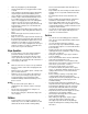
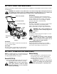
IN WARNING 15° G NTIN E S E EPR E, R OPE ° SL 5 1 A Do not mow on inclines with a slope in excess of 15 degrees (a rise of approximately 2-1/2 feet every 10 feet). A riding mower could overturn and cause serious injury. If operating a walk-behind mower on such a slope, it is extremely difficult to maintain your footing and you could slip, resulting in serious injury. Operate RIDING mowers up and down slopes, never across the face of slopes.
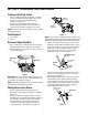
SECTION 3: ASSEMBLING YOUR LAWN MOWER To Remove Unit From Carton • • • Remove staples, break glue on top flaps, or cut tape at carton end and peel along top flap to open carton. Remove loose parts if included with unit (i.e., operator’s manual, etc.). Cut along corners and lay carton down flat. Remove packing material. Roll or slide unit out of carton. Check carton thoroughly for loose parts. Tighten hand knob Tighten hand knob NOTE: Parts included for assembly of grass catcher are listed on page 8.
Assembling Grass Catcher IMPORTANT: Make sure cables are routed to the outside of the handle so they are not in the way when attaching the grass catcher. NOTE: Make certain bag is turned right side out before assembling (warning label will be on the outside). • • Parts for Soft Grass Bag: 1. Front Frame & Rear Frame 2. Grass Bag Assemble grass bag as follows: • • • • Join the rear frame and front frame assembly as shown in Figure 5A. Place bag over frame (black plastic side is the bottom of bag).
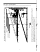
SECTION 4: KNOW YOUR LAWN MOWER Compare the illustration in Figure 9 with your lawn mower to familiarize yourself with the location of various controls and adjustments. WARNING: The operation of any lawn mower can result in foreign objects being thrown into the eyes, which can result in severe eye damage. Always wear safety glasses or eye shields. We recommend wide vision safety mask for over spectacles or standard safety glasses.
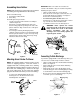
To Start Engine and Engage Blade • WARNING: Never run engine indoors or in enclosed, poorly ventilated areas. Engine exhaust contains carbon monoxide, an odorless and deadly gas. Keep hands, feet, hair and loose clothing away from any moving parts on engine and lawn mower. • • • • • • Move throttle control lever to the fast (rabbit) position. Prime engine as instructed in the separate engine manual packed with your unit.
wheels must be placed in the same relative position. See Figure 10. • • Height Adjustment Lever • • Remove the hairpin clips from the weld pins on the handle brackets. Press outward on the legs of the lower handle, and remove it from the mower. Turn the lower handle around so the notches on the bottom of the lower handle are facing forward as shown in Figure 11. Reassemble, placing the bottom holes in the handle over the weld pins in the handle mounting bracket. Reassemble the upper handle.
NOTE: An unbalanced blade will cause excessive vibration when rotating at high speeds and may cause damage to the mower and/or personal injury. Engine • Lubrication • The blade can be tested by balancing it on a round shaft screwdriver. See Figure 14. Remove metal from the heavy side until it balances evenly. It is recommended that the blade always be removed from the adapter for the best test of balance. Refer to the separate engine manual. (Refer to Lubrication Chart in Figure 15.
SECTION 8: OFF-SEASON STORAGE The following steps should be taken to prepare lawn mower for storage. • • NOTE: When storing any type of power equipment in an unventilated or metal storage shed, care should be taken to rust-proof the equipment. Using a light oil or silicone, coat the equipment, especially cables and all moving parts. • • Clean and lubricate mower thoroughly as described in the lubrication instructions. Refer to engine manual for correct engine storage instructions.
SECTION 10: PARTS LIST FOR MODEL PR-521 1 12 68 69 7 82 9 11 16 83 3 2 4 13 19 A 14 6 57 4 15 79 20 50 54 62 65 81 46 A 76 45 67 44 76 53 39 45 52 58 21 72 56 31 77 40 22 18 47 48 79 80 23 30 80 45 29 76 20 71 66 59 63 55 59 43 41 44 42 45 49 39 64 59 51 32 40 36 76 77 46 34 33 14 17
Model PR-521 Ref. No. Part No. Description Ref. No. 1 647-0004 Control Handle Assembly 46 738-0102 Front Axle Bolt 2 710-1205 Rope Guide 47 720-0190 Spring Lever Knob 3 720-0279 Handle Knob 1/4-20 Thd. 48 732-0417A Rear Spring Lever 4 710-1174 Curved Hd. Bolt 5/16-18 x 2" Lg. 49 14578 Height Adj. Assy. Comp. - RH 6 720-0314 Hand Knob N/I 14579 Height Adj. Assy. Comp. - LH 7 710-1270 Oval C-Sunk Mach. Scr. 50 14765 Pivot Bar R.H. 9 712-0324 Hex L-Nut 1/4-20 Thd.
MANUFACTURER’S LIMITED WARRANTY FOR: TWO-YEAR RESIDENTIAL ONE-YEAR COMMERCIAL Proper maintenance of your Cub Cadet equipment is the owner’s responsibility. Follow the instructions in your operator’s manual for correct lubricants and maintenance schedule. Your Cub Cadet dealer carries a complete line of quality lubricants and filters for your equipment’s engine, transmission, chassis and attachments.