
User Manual

26 PC Series
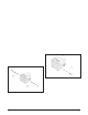
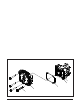
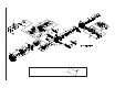
Refer to Figure 6.
Perform disassembly, inspection and assembly on
shock valve one side at a time. Some units vary in
“A” side to “B” side configuration.
Disassembly
1. Remove the shock valve (42) with an 1 1/16-inch
wrench.
2. Remove the shock valve spring and the shock
valve from the end cap.
Inspection
Inspect the shock valve (42) and mating seat in the
end cap for damage or foreign material.
Assembly
1. Position the pump so the shock valve port is
horizontal.
2. Insert the shock valve spring and shock valve
as one assembly into the check plug port. Tighten
to the correct torque value. See Table 2, page
22 (Torque V alues).
3. Repeat disassembly, inspection and assembly
for the opposite port.
REMOVAL, INSPECTION AND/OR
REPLACEMENT OF SHOCK V AL VES
REMOV AL, INSPECTION AND/OR
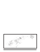
REPLACEMENT OF THE BYP ASS
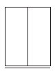
Refer to Figure 7.
Disassembly
1. Loosen the bypass valve (15) using a 7/16-inch
wrench.
2. Remove the bypass (15) from the end cap.
Inspection
1. Inspect the bypass O-rings and mating seats in
the end cap for damage or foreign material.
2. If damaged or worn, replace bypass (15).
Assembly
1. Position the pump so the bypass port is
horizontal.
2. Insert the bypass (15) into the bypass port of
the end cap. T ighten to the correct torque value.
See Table 2, page 22 (Torque Values).
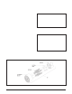
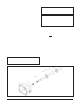
Figure 6. PC Pump Shock V alves
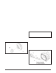
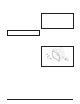
Figure 7. PC Pump Bypass