Professional Shop Manual P90 Series Vertical Shaft Engines NOTE: These materials are for use by trained technicians who are experienced in the service and repair of outdoor power equipment of the kind described in this publication, and are not intended for use by untrained or inexperienced individuals. These materials are intended to provide supplemental information to assist the trained technician.
Table of Contents Chapter 1: Introduction Professional Service Manual Intent . . . . . . . . . . . . . . . . . . . . . . . . . . . . . . . . . . . 1 Safety . . . . . . . . . . . . . . . . . . . . . . . . . . . . . . . . . . . . . . . . . . . . . . . . . . . . . . . . . . 1 Fasteners . . . . . . . . . . . . . . . . . . . . . . . . . . . . . . . . . . . . . . . . . . . . . . . . . . . . . . 3 Assembly instructions . . . . . . . . . . . . . . . . . . . . . . . . . . . . . . . . . . . . . . . . . . . . .
Chapter 4: The Fuel System and Governor Inspecting the fuel . . . . . . . . . . . . . . . . . . . . . . . . . . . . . . . . . . . . . . . . . . . . . . . Test fuel for alcohol . . . . . . . . . . . . . . . . . . . . . . . . . . . . . . . . . . . . . . . . . . . . . . Choke/throttle cable adjustment . . . . . . . . . . . . . . . . . . . . . . . . . . . . . . . . . . . . Carburetors . . . . . . . . . . . . . . . . . . . . . . . . . . . . . . . . . . . . . . . . . . . . . . . . . . . .
Chapter 8: Exhaust Spark arrestor (if equipped) . . . . . . . . . . . . . . . . . . . . . . . . . . . . . . . . . . . . . . . . 79 Muffler removal/replacement . . . . . . . . . . . . . . . . . . . . . . . . . . . . . . . . . . . . . . . 80 Catalytic converter . . . . . . . . . . . . . . . . . . . . . . . . . . . . . . . . . . . . . . . . . . . . . . 82 Chapter 9: Cylinder Head Cylinder head removal . . . . . . . . . . . . . . . . . . . . . . . . . . . . . . . . . . . . . . . . . . .
IV
Introduction CHAPTER 1: INTRODUCTION Professional Service Manual Intent This manual is intended to provide service dealers with an introduction to proven diagnostic and repair procedures for MTD P90 series vertical shaft engines. Disclaimer: The information contained in this manual is correct at the time of writing. Both the product and the information about the product are subject to change without notice.
P90 Series Vertical Shaft Engines • Be prepared in case of emergency: ! CAUTION Keep a fire extinguisher nearby Keep a first aid kit nearby Keep emergency contact numbers handy • Replace any missing or damaged safety labels on shop equipment. • Replace any missing or damaged safety labels on equipment being serviced. • Grooming and attire: ! WARNING Do not wear loose fitting clothing that may become entangled in equipment. Long hair should be secured to prevent entanglement in equipment.
Introduction Fasteners • Most of the fasteners used on the MTD engine are metric. Some are fractional inches. For this reason, wrench sizes are frequently identified in the text, and measurements are given in U.S. and metric scales. • If a fastener has a locking feature that has worn, replace the fastener or apply a small amount of releasable thread locking compound such as Loctite® 242 (blue). • Some fasteners, like cotter pins, are single-use items that are not to be reused.
P90 Series Vertical Shaft Engines MTD Vertical Engine Model Designators 1P61MUA • Starter/Alternator s 1=Recoil start • • • • • Major Revision 2=Electric start (12V) 3=E. start/alt. 18W 4=E. start/alt. 3A/5A 5= AutoChoke/ Recoil 6= AutoChoke/Electric Start 7= AutoChoke/Electric Start/Alt • Change Compliance U H C 0 (Zero) G W P= Vertical (1 cyl.) Q= Vertical (2 cyl.) United States (50 State) Europe California 49 State U.S.(49) and Europe U.S.(50) and Europe Bore Dia.
Introduction Model and serial number The model and serial number can be found on a white sticker with a bar code. The sticker is located between the dipstick and the muffler. See Figure 1.1. Model /serial number Oil screen Muffler Dipstick Figure 1.1 NOTE: The serial number will always start with the model number. Maintenance The recommended maintenance intervals listed in this manual are a guideline. They are adjustable for local conditions.
P90 Series Vertical Shaft Engines Spark plugs The information in this manual applies to the MTD engine. Some basic principles may apply to engines produced by other manufacturers. As the saying goes “an ounce of prevention is worth a pound of cure”. The same can be said about preventive maintenance on outdoor power equipment. By changing the spark plug and oil at recommended intervals many failures can be avoided.
Introduction Air filter Paper-pleated element Foam pre-filter Generally air filters come in two different types, a pleated-paper element or foam. A combination of the two are used on the MTD engine. See Figure 1.3. 1. The main function of the air filter is to trap air borne particles before they enter the engine. Dirt ingestion can cause serious internal engine damage. 2. Air filters used on the MTD engine are designed to prevent particles larger than 3-5 micron from passing through into the engine.
P90 Series Vertical Shaft Engines Oil type and capacity The recommended oil for MTD engines is an SAE 10W-30 oil with an SM API rating or better. The oil capacity for all of the P90 series engines is 57 fl.oz (1.7 liters). • Check the oil level daily and change the oil more frequently in severe operating conditions such as high ambient temperature, dusty conditions, or high load use in exceptionally thick grass. • Synthetic oil is a suitable alternative, but it does not extend service intervals.
Introduction Changing the oil The oil change interval is every 100 hrs. NOTE: The first oil change should be preformed at 8 hours. NOTE: The oil filter should be replaced when the oil is changed. To change the oil: Oil drain Figure 1.5 1/2” hose 1. Remove the cap from the oil drain. See Figure 1.5. 2. Remove the dipstick. 3. Slide a piece of 1/2” hose onto the drain. See Figure 1.6. 4. Route the other end of the hose into an approved oil drain pan. 5.
P90 Series Vertical Shaft Engines Oil filter To replace the oil filter: 1. Drain the oil by following the steps described in the previous section of this chapter. 2. Clean the area around the oil filter 3. Remove the oil filter by turning it counter-clockwise, as seen from the left side of the engine. See Figure 1.7. 4. Place a light coating of oil on the O-ring of the new filter. 5. Pre-fill the new filter with fresh, clean oil. 6. Thread the new filter on to the engine. Hand tighten only. 7.
Introduction Fuel system What you should know about fuel. Most of the fuel presently available in North America is oxygenated to some extent. This is commonly done through the addition of ethanol. Most engines offered for sale on outdoor power equipment in the North American markets are designed to tolerate no more than 10% ethanol by volume Ethanol is hygroscopic, meaning it absorbs water. If left exposed to air, it will draw water out of the air.
P90 Series Vertical Shaft Engines Valve lash Valve lash is the clearance between the top of the valve stem and the rocker arm. The valve lash should be checked after the first 25 hours of use and every 100 hours after that. Valve lash can be checked and adjusted using the following steps:. 1. If the engine has been run, allow it to cool thoroughly. Position the mower for easy access to the cylinder head. 2.
Introduction .005” feeler gauge 6. Check valve lash between each valve stem and rocker arm using a feeler gauge. 7. Intake valve lash (top valve) should be 0.004” 0.006” (0.10 - 0.15mm). See Figure 1.12. 8. Exhaust valve lash (bottom valve) should be 0.006” 0.008” (0.15 - 0.20mm). See Figure 1.13. 9. Use a 10mm wrench to loosen the jam nut, and a 14mm wrench to adjust the rocker arm fulcrum nut. See Figure 1.13. Figure 1.
P90 Series Vertical Shaft Engines Exhaust system The exhaust system is a frequently overlooked component of an engine. It is important to make sure the muffler is in good condition and free of blockage. NOTE: A blocked muffler will result in poor performance. If a muffler is completely blocked, the engine may not start. Cleaning the engine 1. To maintain a proper operating temperature and to keep the equipment looking good, all debris should be removed from the engine. 2.
BASIC TROUBLESHOOTING CHAPTER 2: BASIC TROUBLESHOOTING Definitions Troubleshooting - The act of gathering information by preforming tests and direct observations. Diagnosis - Developing and testing theories of what the problem is, based on the information gathered in troubleshooting. Introduction Diagnosing an engine is an art form that is built upon several factors. First and most importantly is a good understanding of how the engine works. The second is skills that have been honed by experience.
P90 Series Vertical Shaft Engines IV. Unusual exhaust tone There are tools that the technician can use in order to define the problem, such as: 1. Interview the customer. 1a. Get a good description of their complaint. 1b. If it is an intermittent problem, verify what conditions aggravate the problem as best as possible. 1c. Get an accurate service history of the equipment. 1d. Find out how the customer uses and stores the equipment. 2. Direct observation: 2a.
BASIC TROUBLESHOOTING Identify factors that could cause the problem This is the second step in the troubleshooting process. 1. Crankshaft will not turn. A. Starter not working. This can be an electrical failure or a mechanical failure. The likely suspects are: I. A dead battery. II. A bad ground III. A failure in the electrical circuit. IV. A failure of the starter itself. B. Engine in a bind (external - attachment jammed).
P90 Series Vertical Shaft Engines I. Run the engine with a spark tester in-line between the spark plug wire and the spark plug or use an oscilloscope and see if the spark goes away at the same time the engine dies. II. Check choke operation. a. Black smoke? b. Wet plug? III. Prime test immediately after engine dies. If it restarts, this may indicate a problem with fuel flow to the carburetor. Check the gas cap, fuel line, fuel filter, and the float in the carburetor. 3b. Runs with low power output. I.
BASIC TROUBLESHOOTING V. Makes unusual smoke when running a. Black smoke, usually heavy, usually indicates a rich air fuel mixture • Not enough air: air flow blockage or a partially closed choke. • Too much fuel: carburetor float or float valve stuck or metering / emulsion issues with the carburetor. b. White smoke, usually heavy • Oil in muffler, usually the result of improper tipping. The engine will “fog” for a minute or so, then clear-up on its own. • Massive oil dilution with gasoline.
P90 Series Vertical Shaft Engines chirping noise. • Confirm with a compression test and leak-down test. e. Unusual exhaust tone Splashy or blatty • Splashy idle usually indicates a slight rich condition. • May indicate an exhaust blockage, usually slightly muffled. Backfire • On over-run: unburned fuel igniting past exhaust valve. Mixture not burning completely in combustion chamber. It may be too rich or it may be spark-plug or ignition problem.
BASIC TROUBLESHOOTING Repairing the problem The third step in the troubleshooting process is to repair the problem. This step consists of: A. Form a diagnosis by using all of the information gathered from the troubleshooting that was performed. B. Physically perform the repair. The fourth, and hopefully final, step in the troubleshooting process is the follow through. This step consists of: A. Thoroughly test the repaired equipment: confirming that the initial diagnosis was correct.
P90 Series Vertical Shaft Engines Prime test To perform a prime test: 1. Prime the engine through the carburetor throat using a squirt bottle, filled with clean fresh gasoline. 2. Make sure the throttle is in the run position. 3. Attempt to start the engine. 4. If the engine starts and runs long enough to burn the prime, the problem is effectively isolated to the fuel system. Proceed to Chapter 4: The Fuel System and Governor. 5.
BASIC TROUBLESHOOTING 7. Compare the results to the following chart. Leak-down Testing Results Symptom Possible cause Air escaping from the breather Worn cylinder or piston rings.
P90 Series Vertical Shaft Engines Compression test To perform a compression test: NOTE: Compression should be in the range of 55 - 80 PSI (3.8 - 5.5 Bar). • Disconnect the high-tension lead from the spark plug and ground it well away from the spark plug hole. • Remove the spark plug using a 13/16” or 21mm wrench. A flexible coupling or “wobbly” extension may help. • Pull the starter rope several times to purge any fuel or oil from the combustion chamber. NOTE: Air compresses readily, liquid does not.
BASIC TROUBLESHOOTING PCV testing The PCV (Positive Crankcase Ventilation) valve is located in the engine block and allows the crankcase pressure to escape. Leakage and blockage are the two failure modes for a PCV system. Either mode will cause crankcase pressure to build-up, though the effects of a blocked PCV are generally more dramatic. Increased case pressure will result in oil entering the combustion chamber. 1. The PCV chamber is vented to the intake manifold through a rubber hose.
P90 Series Vertical Shaft Engines 26
AIR INTAKE SYSTEM CHAPTER 3: AIR INTAKE SYSTEM Air filter Paper-pleated element Generally air filters come in two different types, a pleated-paper element or foam. A combination of the two are used on the MTD engine. See Figure 3.1. • Air filters used on the MTD engine are designed to prevent particles larger than 3-5 micron from passing through into the engine. • The filter should be checked on a regular basis possibly several times in a season.
P90 Series Vertical Shaft Engines 3. Lift the air filter cover off the engine. 4. Remove the air filter assembly. Air filter Figure 3.3 5. Install the air filter by following the previous steps in reverse order. NOTE: The air filter housing is part of the blower cover. The intake manifold extends through a hole in the bottom of the air filter housing. When installing the air filter, the hole in the bottom of the paper element must fit over the intake manifold. See Figure 3.4.
AIR INTAKE SYSTEM Blower/air filter housing On the P90 series of engine, the air filter housing is part of the blower housing. To remove/replace the blower/air filter housing: 1. Remove the air filter following the steps described in the previous section of this chapter. 2. Remove the nut that was under the air filter (indicated by the arrow in Figure 3.5.) using a 10mm wrench. 3. Loosen the two shoulder bolts (indicated by the arrows in Figure 3.6.) using a 12 mm wrench. 4.
P90 Series Vertical Shaft Engines Carburetor and Insulator To remove/replace the carburetor and insulator block: 1. Remove the blower/air filter housing by following the steps described in the blower/air filter housing section of this chapter. 2. Disconnect the breather hose from the intake manifold. See Figure 3.8. EVAP port Breather hose NOTE: On units equipped with an evaporative emissions system, disconnect the hose from the EVAP port of the intake manifold.
AIR INTAKE SYSTEM 6. Double nut the carburetor studs and remove them. See Figure 3.10. NOTE: The insulator block and gaskets may fall out when the studs are removed. NOTE: The most likely reason to remove the insulator block and its gaskets is to cure a lean running condition. Inspect all removed parts carefully to identify the point where additional air is entering the intake tract. Double nut 7. Disconnect the choke linkage. 8. Disconnect the throttle linkage and spring. 9.
P90 Series Vertical Shaft Engines 11. Install the carburetor by following the previous steps in reverse order. Gasket NOTE: Use new gaskets between the cylinder head, the insulator, the carburetor and the intake manifold. NOTE: Tighten the carburetor nuts to a torque of 62 - 80 in lbs (7 - 9 Nm). 12. Gasket Gasket Studs Test run the engine before returning it to service. Insulator Carburetor Figure 3.
FUEL SYSTEM AND GOVERNOR CHAPTER 4: THE FUEL SYSTEM AND GOVERNOR The function of the fuel system is to store fuel, mix the fuel with air in the correct ratio and deliver it to the intake port. The fuel system consists of the following components: • Fuel tank • Fuel lines • Fuel filter • Carburetor and insulator block NOTE: When working on the fuel systems, look at the whole system. A problem will rarely be isolated to one component.
P90 Series Vertical Shaft Engines Test fuel for alcohol Fuels currently on the market contain a wide array of additives. Some of these additives oxygenate the fuel. Oxygenated fuel reduces emissions, and is required in some parts of the United States. Fuel make-up varies seasonally and geographically. Ethanol is the primary additive used to oxygenate fuel. Ethanol in fuel creates a lot of problems for gasoline engines. The biggest problem is that alcohol attracts and holds water.
FUEL SYSTEM AND GOVERNOR Choke/throttle cable adjustment The choke/throttle cable will need to be adjusted any time the cable or the control panel is replaced. NOTE: The procedures to remove/replace the choke/throttle cable can be found in the service manual for the piece of equipment that the engine is mounted to. Choke lever NOTE: The choke should be opened when the engine starts. This can be a source of starting issues with customers who are not familiar with manual chokes.
P90 Series Vertical Shaft Engines Carburetors If diagnosis indicates a fuel problem, inspect the carburetor. This is important even if problems are identified elsewhere in the fuel system. IMPORTANT: The fuel must be tested for alcohol content before diagnosing anything else on the engine. NOTE: It is important to perform a compression or leak down test before condemning a carburetor.
FUEL SYSTEM AND GOVERNOR Disassembly and rebuilding the carburetor 1. Remove the carburetor by following the procedures described in Chapter 3: Air Intake System. NOTE: An insulator separates the carburetor from the cylinder head. • A bowl vent port is in a recessed passage on the end of the carburetor that faces the insulator. • A second passage in the insulator supplements the passage on the carburetor. • Gaskets separate the insulator from the cylinder head and the carburetor from the insulator.
P90 Series Vertical Shaft Engines NOTE: Because the float valve is crucial to the functioning of the carburetor and the viton tip of the valve is subject to wear, technicians should replace the valve and spring any time the carburetor is disassembled for cleaning. Float Float valve NOTE: If the needle seat is worn or damaged, the carburetor must be replaced. Compression spring Figure 4.8 6. Remove the main jet using a narrow-shank straight blade screwdriver. See Figure 4.9.
FUEL SYSTEM AND GOVERNOR Throttle stop screw 7. The throttle stop screw has a large pliable lip around the head of the screw. That lip secures a metering plug for the pilot and transition ports. Remove the screw to reach the plug. See Figure 4.11. 8. Carefully pry out the metering plug and spacer using a small screwdriver. See Figure 4.12. Welch plug Shot plug in feed bore Fuel feed leg on central column for pilot and transition Fuel port to central column Figure 4.
P90 Series Vertical Shaft Engines Transition ports NOTE: The pilot screw regulates how much of this pre-mixed fuel/air emulsion is allowed to enter the throat of the carburetor, to atomize down-stream of the throttle plate. On current production units, it is set at the factory and the screw head is removed. See Figure 4.14. Pilot port Pilot screw (before head is removed) NOTE: The transition ports are fixed. They are drilled into the throat of the carburetor, down-stream of the venturi.
FUEL SYSTEM AND GOVERNOR Engine speed adjustment To adjust the engine speed: Tab 1. Start the engine and let it reach operating temperature. 2. Move the throttle control lever to the full throttle position. 3. Measure the engine’s speed using a tachometer. 4. Bend the tab, that the governor spring is attached to, as needed to adjust the engine speed to 3,300 RPM + 100. See Figure 4.15. • Bend the tab up to increase speed. • Bend the tab down to decrease speed. Figure 4.
P90 Series Vertical Shaft Engines Afterfire solenoid When an engine is turned off, the engine does not “instantly” stop spinning. As the engine slows down, it is still drawing fuel out of the carburetor. This raw fuel passes through the engine because the ignition system is grounded to prevent the spark plug from firing. When the raw fuel reaches the hot muffler it can ignite, resulting in an afterfire.
FUEL SYSTEM AND GOVERNOR Old style NOTE: Early production engines have a simple bullet connector between the stator and the afterfire solenoid (power lead). Current production engines have locking bullet connectors. The two connectors are not interchangeable. All new stators and afterfire solenoids sold as service parts will have the new connectors. NOTE: All service replacement stators and afterfire solenoids will be shipped with an adaptor and an instruction sheet on how to use the adaptor, if needed.
P90 Series Vertical Shaft Engines Testing the afterfire solenoid An afterfire solenoid that is not working properly can prevent the engine from starting. The solenoid itself rarely fails, usually there is some type of fault in the wiring to the solenoid to prevent it from energizing. To determine if the afterfire solenoid is faulty: 1. Test the unit’s battery. • 2. The battery must be fully charged before any testing can be preformed.
FUEL SYSTEM AND GOVERNOR 5. Afterfire solenoid lead from main harness With the ignition key in the “on” position, test for voltage at the power lead connection. See Figure 4.21. • If battery voltage is present, bench test the solenoid. • If the voltage at the connection is not the same as the battery voltage or there is no voltage, the problem is with the equipment’s electrical system and not the solenoid.
P90 Series Vertical Shaft Engines Governor The engine speed is controlled by a balance between the force applied by a spring (pulling the throttle open) and a flyweight mechanism within the engine applying force to the governor arm (pushing the throttle closed). See Figure 4.23. Throttle linkage Spring tension NOTE: While the mechanism is simple and robust, it is important to pay attention when working on parts near the governor.
FUEL SYSTEM AND GOVERNOR 8. Put an alignment mark on the governor arm and shaft. See Figure 4.26. 9. Loosen the nut and T-bolt that secures the governor arm to the shaft. 10. Carefully spread open the seam on the arm. 11. T-bolt Carefully slide the Governor arm off of the governor shaft. 12. Unhook the governor linage and throttle return spring. 13. Unhook the governor spring. Figure 4.26 To install the governor arm: 1. Attach the throttle linkage and return spring. 2.
P90 Series Vertical Shaft Engines Governor shaft To remove or replace the governor shaft: 1. Remove the engine from the equipment that it powers. 2. Remove the governor arm by following the procedures described in the governor arm section of this chapter. 3. Remove the sump cover by following the steps described in Chapter 10: Cam, Crankshaft and Piston. 4. Remove the hairpin clip from the governor shaft. See Figure 4.27. 5.
Lubrication CHAPTER 5: LUBRICATION Oil type and quantity The recommended oil for MTD engines is an SAE 10W-30 oil with an SM API rating or better. The oil capacity for all of the P90 series engines is 57 fl.oz (1.7 liters). ) ) ) ) ) ) ) 6$( 6$( 6$( : 6$( : 6$( : & & & & & & & 2LO &KDUW • If the oil is noticeably thin, or smells of gasoline, carburetor repair may be needed before the engine can be run safely.
P90 Series Vertical Shaft Engines Oil dipstick To check the oil: 1. Twist and remove the dipstick from the engine. 2. Clean the oil off of the tip of the dipstick. 3. Re-insert the dipstick and turn it until it is fully seated to get the oil level reading. See Figure 5.1. 4. The oil level is determined by the highest point on the dipstick that is completely covered with oil. Fully seat the dip stick before reading it Dipstick Figure 5.
Lubrication Lubrication system Balance shaft The 4P90 engine uses a combination pressurized and splash lubrication system. There is an oil pump in the sump that is driven by the balance shaft. The oil is drawn into the pump through a pre-screen. The pump pushes the oil through a relief valve then into the oil filter. From the filter, the oil flows through a passage in the sump cover until it reaches the crankshaft PTO bearing.
P90 Series Vertical Shaft Engines 2. Check the oil level. NOTE: Top off the oil as needed with an SAE 10W30 oil with an SM API rating or better 3. Start the engine. 4. Let the engine run until the oil reaches operating tempurature 176° - 212° (80° - 100°C). 5. With the engine at 3,300 RPM, the oil pressure should reading be a minimum of 5 psi (0.3 bar). See Figure 5.6.
Lubrication Positive crankcase ventilation valve The PCV valve is located under the flywheel and allows the crankcase pressure to escape. The function and test procedures for the PCV is covered in Chapter 2: Basic Troubleshooting. To service the PCV: PCV cover 1. Remove the flywheel by following the steps described in the Chapter 7: Ignition System. 2. Remove the five screws that hold the PCV chamber cover to the engine block using a 10mm wrench. See Figure 5.7. 3.
P90 Series Vertical Shaft Engines 6. Inspect the oil drain-back port. Make sure it will allow oil to drain back into the engine. See Figure 5.10. 7. Reassemble the PCV valve. 8. Tighten the cover bolts to a torque of 53 - 71 in lbs (6 - 8Nm). Oil drain port Figure 5.10 9. Inspect the PCV tubing for cracks, brittleness or signs of leaking. Replace the PCV tube if any are found. See Figure 5.11. 10. Re-assemble the engine by following the above steps in reverse order. 11.
Starter and Charging System CHAPTER 6: STARTER AND CHARGING SYSTEMS Starter removal To remove/replace the starter assembly: Starter screws 1. Disconnect the negative battery cable. 2. Disconnect the starter cable using a 10 mm wrench. 3. Remove the two screws that secure the starter to the engine using a 12 mm wrench. See Figure 6.1. 4. Slide the starter off of the dowel pins, indicated by the arrows in Figure 6.2. 5. Install the starter by following the previous steps in reverse order.
P90 Series Vertical Shaft Engines Bench testing the electric starter IMPORTANT: Always bench test an electric starter before condemning it. To bench test an electric starter: 1. Remove the starter by following the procedures described in the previous section of this chapter. 2. Mount the starter in a vise. NOTE: If the vise is tightened too tight, the starter can be crushed. 3. Negative lead Attach the negative lead of a 12 volt power source to the starter housing.
Starter and Charging System Rebuilding the starter The starter motor used on the 4P90 engine is a permanent magnet dc motor with a radial commutator, similar to what is found in a repulser start motor. A radial commutator means that the commutator plates are perpendicular to the axis of the rotor. Springs With this arrangement, the brushes and brush holder are mounted to the end cap and the rotor will ride on top of them. Brushes Figure 6.4 Starter motor disassembly: Stator housing 1.
P90 Series Vertical Shaft Engines 5. Slide the stator housing off of the starter. 6. Pull the rotor out of the stator housing. NOTE: The rotor will be held to the stator by strong magnets. 7. Inspect the rotor for signs of wear or damage. 8. If the rotor is damaged, it may not be economically feasible to rebuild the starter. 9. Test the rotor: 9a. Set the DMM to measure resistance (Ω scale). 9b. Measure the resistance across all of the commutator plates. • 9c.
Starter and Charging System Washers Nut 12. Remove the nut and washers from the cable stud using a 10 mm wrench. See Figure 6.10. 13. Remove the cable stud and the positive brushes. 14. Remove the insulator seal. Seal Figure 6.10 5/16” punch 15.Remove the bearing: 15a. Fill the bearing hole with grease. 15b. Insert a 5/16” pin punch. 15c. Tap the punch with a hammer to hydraulically press the bearing out of the end cap.
P90 Series Vertical Shaft Engines 17. Remove the screw, indicated by the arrow in Figure 6.13., from the topside of the starter gear housing using a #2 phillips screwdriver. Figure 6.13 18. Separate the starter gear housing. See Figure 6.14. 19. Remove the pinion gear. 20. Remove the bendix gear assembly. Bendix gear pinion gear Figure 6.14 21. Remove the bushing from the starter gear housing. See Figure 6.15.
Starter and Charging System Screw extractor 22. Remove the bushing from the clutch/pinion cover. See Figure 6.16. NOTE: A blind hole bearing puller with a 11mm arbor or an screw extractor can be used. Figure 6.16 23. Drive the rotor upper bearing out of the clutch/pinion cover using a flat tipped punch. See Figure 6.17. rotor upper bearing Figure 6.
P90 Series Vertical Shaft Engines To re-assembly a starter motor: 1. Press the bushing into starter gear housing until there is 0.055” (1.4 mm) sticking out. See Figure 6.18. 0.055” Figure 6.18 2. Press the rotor’s upper bearing into the clutch/pinion cover until it is flush with the cover. See Figure 6.19. Bearing Figure 6.19 3. Press the bushing into the clutch/pinion cover until it is flush. See Figure 6.20. Bushing is flush with the casting Figure 6.
Starter and Charging System Clutch/pinion gear assembly 4. Insert the clutch/pinion gear assembly into the starter gear housing. See Figure 6.21. 5. Install the pinion gear. See Figure 6.22. 6. Mount the clutch/pinion cover to the starter gear housing. Figure 6.21 Pinion gear clutch/pinion cover Figure 6.22 NOTE: Apply a thread locking compound, such as Loctite® 262, to the threads of the screws before installing them.
P90 Series Vertical Shaft Engines 7. Clean the carbon from the commutator. NOTE: A pencil eraser is very effective in cleaning commutators. See Figure 6.24. Figure 6.24 8. Insert the splined end of the rotor into the starter gear housing. See Figure 6.25. Rotor assembly Figure 6.25 9. Slide the stator housing over the rotor assembly. Keep fingers clear while sliding the stator housing over the rotor.
Starter and Charging System 11. Bushing is flush with casting Press a new bushing into the end cap until it is flush with the casting. See Figure 6.27. Figure 6.27 positive brushes/cable stud assembly 12. Insert the seal into the end cap from the inside. 13. Install the positive brushes/cable stud assembly. 14. Install the insulator washer. See Figure 6.28. 15. Install the flat washer against the insulator washer. 16. Install the lock washer. 17.
P90 Series Vertical Shaft Engines NOTE: A special tool will be needed to compress the brushes for assembly of the motor. See Figure 6.30. To make the tool: A. Cut a piece of sheet metal approximately 0.040” thick (19 or 20 gauge). 1 5/8” 5/8” 2” B. Cut a slot in the metal, 5/8” wide x 1 5/8” long. C. Buff and debur all edges of the tool. 4.5” Figure 6.30 21. Insert the brushes into the brush holder.
Starter and Charging System 22. Set the starter motor onto the end cap while keeping the brushes compressed into the brush holder. See Figure 6.33. 23. Carefully slide the brush holding tool out of the starter. 24. Rotate the end cap to line up the alignment marks with the stator housing. NOTE: Keep the starter motor compressed together. 25. Install the two screws that secure the end cap to the starter motor. Figure 6.33 26. Bench test the starter before installing it on the engine.
P90 Series Vertical Shaft Engines Charging system The charging system used on MTD engines consists of a dual output alternator and a rectifier/regulator. The charging system has a 5 amp AC output and a 3.75 amp DC output. The alternator consists of two parts; the rotor and the stator. • Alternator rotor: The rotor consists of five magnets on the inside of the flywheel that rotate around a stator that is mounted to the cylinder block.
Starter and Charging System Charging system testing To test the charging system: Engine harness connector 1. Locate the connection between the engine harness and the main harness of the machine. See Figure 6.37. 2. Start the engine and run it at full throttle. 3. Check the engine RPMs. NOTE: The engine must be at 3,300 RPMs to test the alternator output. Figure 6.37 Positive probe 4. Connect the black (-) lead of a digital multimeter to a good ground on the engine. 5.
P90 Series Vertical Shaft Engines 11. If the results do not match the specifications: 11a. Turn off the engine. 11b. Disconnect the regulator/rectifier. 11c. Start the engine again and run it at full throttle. 12. Set the multimeter to read AC voltage. 13. Connect the black (-) lead of a digital multimeter to a good ground on the engine. 14. Connect the red probe to one of the red wires from the stator harness. See Figure 6.40. NOTE: The meter should read 8.5 to 10 Vac. 15.
Starter and Charging System Stator To remove/replace the stator: 1. Remove and ground the spark plug wire. 2. Remove the flywheel by following the steps described in Chapter 7: Ignition System. 3. Remove the starter by following the procedures described in the starter section of this chapter. 4. Remove the two screws, indicated by the arrows in Figure 6.41., that secure the stator with a 10mm wrench. 5. Remove the two screws, indicated by the arrows in Figure 6.42.
P90 Series Vertical Shaft Engines Rotor Rotor failures are extremely rare. To check the rotor: • Confirm that the magnets are firmly attached to the flywheel. • Hold a screwdriver or a similar tool made of ferrous metal within a 1/4” of each magnet. • If the tool is drawn to the magnet, the rotor is good. Figure 6.
Ignition System CHAPTER 7: IGNITION SYSTEM Troubleshooting the ignition system The purpose of the ignition system is to provide a spark in the combustion chamber at the proper time to efficiently ignite the fuel/air mixture. The steps in troubleshooting the ignition system are: 1. Spark tester Examine the spark plug(s) by following the steps described in the spark plug section of this chapter. NOTE: It is convenient to check the compression when the spark plug is removed for examination. 2.
P90 Series Vertical Shaft Engines The module The coil in this ignition system is an inductive discharge magneto, contained in a single module. • The inductive discharge module has a two leg design. • The module is energized by the passing of a magnet mounted in the flywheel. • Ignition timing is set by the location of the flywheel in relation to the crankshaft. Proper timing is maintained by a steel key. Normal performance of the coil is to produce at least 10,000 volts at start-up speed.
Ignition System Module removal Afterfire solenoid lead 1. Unplug the spark plug. 2. Remove the blower/air filter housing by following the steps procedures in Chapter 3: Air Intake System. 3. Disconnect the module wire that goes to the system harness. See Figure 7.3. 4. Remove the module using a 10 mm wrench. Module wire Figure 7.3 NOTE: The engine model number is on the module. When installing a new module, make sure the model numbers match. See Figure 7.4. Engine model number Figure 7.
P90 Series Vertical Shaft Engines Installing the module and setting the air gap NOTE: If just setting the air gap, loosen the module mounting screws first then follow the procedures described below. 1. Rotate the flywheel so that the magnets are away from where the module is mounted. 2. Install the module. Do not tighten the module screws. 3. Place a non-ferrous feeler gauge between the module and the flywheel. Plastic feeler gauge NOTE: The air gap should be 0.016” - 0.024” (0.40.6 mm). 4.
Ignition System Flywheel The flywheel holds the magnets. These magnets induce a field in the module which in turn produces a spark. It also controls the timing of the ignition system by controlling when the magnets are introduced to the module. A sheared flywheel key will throw off the ignition timing. Sheared keys are uncommon on MTD engines. If one is found, check the crankshaft and flywheel for damage. To Remove and/or inspect the flywheel and key: 1.
P90 Series Vertical Shaft Engines Spark plug • The spark plug is a F6RTC, part #951-10292, gapped to 0.024” - 0.031” (0.6 - 0.8 mm). • Wear rate will vary somewhat with severity of use. If the edges of the center electrode are rounded-off, or any other apparent wear / damage occurs, replace the spark plug before operating failure (no start) occurs. Cleaning the spark plug • Cleaning the spark plug is not recommended. If the plug needs to be cleaned, replace it.
Exhaust CHAPTER 8: EXHAUST The exhaust system is a frequently overlooked component of an engine. It is important to make sure the muffler is in good condition and free of debris and/or insects. NOTE: A blocked muffler will result in poor performance. If a muffler is completely blocked, the engine may not start. Spark arrestor (if equipped) A spark arrestor, part #951-12329, is available as an option. NOTE: Spark arrestors are an option that are required on all engines used in California and U.S.
P90 Series Vertical Shaft Engines Muffler removal/replacement 1. Remove the four screws, indicated by the arrows in Figure 8.2. that retain the muffler shield using a 10mm wrench and lift it off of the engine. 2. Lift the muffler shield off of the engine. Figure 8.3 3. Remove the screw, indicated by the arrow in Figure 8.4. that secures the rear of the muffler to the engine block using a 10mm wrench. Figure 8.4 4.
Exhaust 6. Clean all of the gasket material off of the cylinder head and the muffler. See Figure 8.6. NOTE: The MTD engine uses a graphite exhaust gasket. It is not reusable and must be replaced every time the muffler nuts are loosened. NOTE: The graphite exhaust gasket transfers heat from the cylinder head to the muffler. The heat transfer helps to keep the engine operating temperature under control. Do not substitute an exhaust gasket made from another material. 7. Remove all gasket material Figure 8.
P90 Series Vertical Shaft Engines Catalytic converter On engines equipped with a catalytic converter muffler, there is an air injector assembly on the cylinder head, as show in Figure 8.7. There is a passage from the air injector to the exhaust port. When the exhaust valve is open the gases inside the engine escape to the muffler at great velocity. The pressure of the exhaust gases will close the reed valve in the air injector, preventing them from escaping through the injector.
Cylinder head CHAPTER 9: CYLINDER HEAD Cylinder head removal The Cylinder head of the MTD engine can be removed without removing the engine from the piece of equipment. To remove the cylinder head: 1. Disconnect and ground the spark plug high tension lead. 2. Remove the blower/air filter housing, carburetor and insulator plate by following the steps described in Chapter 3: Air Intake System. NOTE: The fuel line and the linkages can be left attached to the carburetor.
P90 Series Vertical Shaft Engines 6. Remove the two screws, indicated by the arrows in Figure 9.3, that secure the baffle to the cylinder using an 8 mm wrench. 7. Remove the baffle. Figure 9.3 8. Remove the spark plug using a 13/16” or 21mm wrench. 9. Rotate the crankshaft until it is at TDC of the compression stroke by following the steps described in the valve lash section of Chapter 1: Introduction. 10. Remove the four screws securing the valve cover using a 10mm wrench. See Figure 9.4.
Cylinder head Sealing surface 14. Lift the cylinder head off of the engine. 15. Carefully clean all sealing surfaces of all gasket residue. Do not scratch the sealing surfaces. See Figure 9.6. surface NOTE: If replacing the head, double-nut and remove the exhaust studs. NOTE: Make a visual inspection of the valves and cylinder bore to confirm the initial diagnosis. Figure 9.
P90 Series Vertical Shaft Engines Cylinder head installation 1. Place a new head gasket on the cylinder, allowing the alignment dowels to hold it in place. See Figure 9.7. NOTE: The 4P90 series of engines use a metal head gasket with rubber seals. Dowel pins Figure 9.7 2. Position the cylinder head on the engine block. 3. Install the 4 head bolts, and tighten them to a step torque of 41 - 44 ft lbs. (55 - 60 Nm) in an alternating diagonal pattern. See Figure 9.8.
Cylinder head Valves The valves and valve seats can be serviced by grinding and lapping or the head can be replaced. Depending on local machine and labor costs, it is probably more economical to replace the cylinder head versus servicing the valves. To service the valves: Valve adjusters NOTE: Servicing valves during the warranty period will void the warranty. Warranty valve repairs are to be accomplished by replacing the cylinder head. 1.
P90 Series Vertical Shaft Engines 5. Lift the springs off of the valve stems. 6. Slide the valves out of the cylinder head. NOTE: Only the intake valve has a valve guide seal. See Figure 9.11. Seal Figure 9.11 7. Inspect the valve seat. See Figure 9.12. • Valve seats are 45 degrees, with a 25 degree topping cut and a 60 degree narrowing cut. • Seat width should be 0.028” - 0.035” (0.7 0.9mm) with a margin of 0.049” - 0.061 (1.25 1.55 mm) on the exhaust valve and 0.027” (1mm) on the intake valve.
Cylinder head 11. Test the valves for leaks by: 11a. Place the cylinder head on a couple of wood blocks with the valves facing up. 11b. Pour a small amount of gasoline or parts cleaning solvent into the combustion chamber (just enough to cover the valves). 11c. Let the cylinder head sit for ten minutes. 11d. Check for gasoline leaking out of the intake and exhaust ports. 12. Install the cylinder head by following the steps described earlier in this chapter. 13.
P90 Series Vertical Shaft Engines Push rod guide plate The push rods move through a guide plate that aligns the push rods with the rocker arms. The guide plate also acts as a bushing for the push rods. Over time, the guide plate will wear out and need to be replaced. NOTE: A guide plate that is worn out can allow the push rod to slip out from under the rocker arm. When that happens, the push rod will side load the rocker arm, breaking the rocker arm stud. To service the push rod guide plate: 1.
Crankshaft, piston and connecting rod CHAPTER 10: CRANKSHAFT, PISTON AND CONNECTING ROD The exact procedure a technician uses to disassemble an engine depends on the type of repairs needed. This chapter is written as a set of procedures that should provide the user with sufficient information to complete any feasible repair to the engine short block assembly. The instructions are written with the assumption that the engine has been removed from the equipment. These are bench work instructions.. 1.
P90 Series Vertical Shaft Engines 11. Align the timing marks on the cam and the crankshaft to allow easier removal of the cam and to help protect the compression relief from damage. See Figure 10.2. NOTE: The timing marks were filled in with red paint for the picture. 12. Remove the camshaft. Timing marks Figure 10.2 13. Remove the balance shaft. See Figure 10.3. Remove the balance shaft Cam shaft Compression relief Figure 10.
Crankshaft, piston and connecting rod 15. Match mark the connecting rod and cap. 16. Remove the connecting rod cap using a 10mm wrench. See Figure 10.5. NOTE: Rotating the crank shaft after the connecting rod bolts are removed will help to separate the connecting rod from the cap. Remove the connecting rod bolts Figure 10.5 17. Push the piston out of the cylinder. Remove one of the piston pin retainers NOTE: Sometimes a ridge of carbon builds up where the cylinder meets the head.
P90 Series Vertical Shaft Engines Crankshaft inspection 1. Inspect the crankshaft journals and the crank pin for galling, scoring, pitting or any other form of damage. NOTE: This is mostly a visual check. Measurement is to determine if it is within the specifications after it is found to be OK visually. NOTE: The crankshaft and bearing are serviced as one assembly. 2. Measure the crank pin where the connecting rod attaches to the crankshaft using a vernier caliper or a micrometer. See Figure 10.8.
Crankshaft, piston and connecting rod Piston Inspection 1. Clean the piston and remove all carbon from the rings and ring groves. 2. Clean the cylinder bore and remove all carbon. 3. Insert one ring into the cylinder. Push it down about one inch from the top. See Figure 10.9. 4. Measure the end gap with a feeler gauge and compare to the chart at the end of this chapter. See Figure 10.9. 5. Repeat steps 3 and 4 on the other rings. Piston ring Feeler gauge Figure 10.
P90 Series Vertical Shaft Engines 7. Measure the gap between the ring and the ring land using a feeler gauge and compare the measurement to the chart at the end of this chapter. See Figure 10.12. Feeler gauge Figure 10.12 8. Measure the piston pin bore on both sides of the piston using telescoping gauges or vernier caliper. See Figure 10.13. NOTE: Measurements should be taken at right angles to check the roundness of the holes. Piston pin bore Figure 10.13 9.
Crankshaft, piston and connecting rod Connecting rod inspection Measure at right angles Measure at right angles 1. Inspect the connecting rod for cracks or any signs of damage. 2. Install the rod cap and tighten to a torque of 177 - 212 in-lbs (20 - 24 Nm). 3. Measure the inside diameter of the connecting rod at both ends and compare the measurements to those listed in the chart at the end of this chapter. See Figure 10.15. NOTE: Take two measurements 90 degrees apart.
P90 Series Vertical Shaft Engines Balance Shaft There are two primary motions that generate most of the vibrations in single-cylinder engines; the rotation of the crankshaft, and the reciprocating motion of the piston. See Figure 10.17. Piston travel Connecting rod Crankshaft travel Figure 10.17 Rotating mass The connecting rod translates the linear motion of the piston to the rotating motion of the crankshaft.
Crankshaft, piston and connecting rod Reassembly 1. Clean the cylinder 1a. Remove all gasket material from all mating surfaces. 1b. Clean the cylinder and crank case cover. 2. Oil seals 2a. Install a new oil seal in the cylinder block. 2b. Install a new seal in the crank case cover. 3. Insert the crankshaft and bearing into the cylinder block. NOTE: Pre-lube the crankshaft with clean 10W-30 motor oil.
P90 Series Vertical Shaft Engines 5. Install the balance shaft by: 5a. Pre-lube the balance shaft with clean 10W-30 motor oil 5b. Rotate the crankshaft until the timing mark on the larger gear points to the 7:30 position. 5c. Insert the balance shaft, aligning the timing marks. See Figure 10.22. Timing marks NOTE: The timing marks were marked with red paint for the picture. 6. Install the valve tappets. 7. Install the cam shaft by: 7a. Pre-lube the cam shaft with clean 10W-30 motor oil 7b.
Crankshaft, piston and connecting rod Engine specifications chart Specification Minimum Maximum in mm in mm in mm Bore 3.544” 90.01 3.544” 90.02 3.553” 90.25 Cylindricity 0.000” 0.000 0.000” 0.008 0.000” 0.008 Cylinder taper 0.000” 0.000 0.000” 0.000 0.000” 0.000 Displacement Service Limit 25.6 cu. in (420 cc) Crankshaft journal OD (flywheel end) 1.375” 34.94 1.377” 34.98 1.369” 34.77 Crankshaft journal OD (flywheel end) 1.377” 34.98 1.378” 34.99 1.370” 34.
P90 Series Vertical Shaft Engines Specification Minimum Maximum Service Limit Compression ring end gap 0.008” 0.20 0.016” 0.40 0.039” 1.00 Scraper (second) ring end gap 0.008” 0.20 0.016” 0.40 0.039” 1.00 Compression ring to land clearance 0.001” 0.02 0.002” 0.06 0.008” 0.20 Scraper (second) ring to land clearance 0.001” 0.02 0.002” 0.06 0.008” 0.20 Intake valve lash 0.004” 0.10 0.006” 0.15 Exhaust valve lash 0.006” 0.15 0.008” 0.20 spark plug gap 0.024” 0.60 0.
Crankshaft, piston and connecting rod Engine torque values chart Fastener in lbs Nm Blower housing studs 80 - 106 9 - 12 Breather cover 53 - 71 6-8 Carburetor drain bolt 49 - 80 5.
P90 Series Vertical Shaft Engines 104
Failure Analysis CHAPTER 11: FAILURE ANALYSIS A properly maintained engine will provide years of service. Occasionally an engine will fail. An important part of working on engines is being able to recognize the root cause of engine failures. Was it something the customer did? Was it a manufacturing defect? Did the engine just wear out? All of these questions need to be answered. Identifying and eliminating the cause of the failure is the only way to prevent recurring failures.
P90 Series Vertical Shaft Engines 5. 6. When particles enter the combustion chamber, the up and down motion of the piston grinds the particles into the side of the cylinder walls and damages the cylinder wall, piston and piston rings. Cross hatch polished off This can be identified by the scoring along the vertical axis of the piston and cylinder wall or the cross hatch on the cylinder wall being worn off.
Failure Analysis 8. Because the oil suspends the particles, the engine components that are immersed in oil will show definite signs of abrasive ingestion especially around the connecting rod and main bearing journals. See Figure 11.5. NOTE: Abrasives that are trapped in the oil will cause the lower portion of the combustion chamber to wearing more than the upper portion. NOTE: Wear of only one bearing surface on a new engine could be a sign of a manufacturing defect. Figure 11.
P90 Series Vertical Shaft Engines Insufficient lubrication The bearing surfaces in an engine are not smooth. The machining processes used to make the engine parts, leave little peaks and valleys that are only visible under a microscope. These peaks are called asperities. As the engine breaks in, the asperities break off leaving plateaus that become the bearing surface. The valleys become reservoirs for the lubricant.
Failure Analysis Discoloration 3. Metal transfer is the primary indicator that the film of oil between two engine parts has been violated. If the damage is localized, a general failure of the lubrication system is probably not the cause. As an example: a piston skirt shows metal transfer to the cylinder wall. The connecting rod and wristpin show some signs of excessive heat. The main bearings and camshaft are not damaged. This would indicate that the problem was probably related to cylinder temperature.
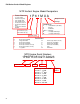
P90 Series Vertical Shaft Engines Engine Overspeed The MTD engine is designed for a maximum speed of 3300 rpm. When the governor is unable to control the engine rpm, the engine can accelerate past the safe maximum speed. When an engine runs beyond its designed speed, a few things happen: 1. As the piston moves up and down in the cylinder, it builds momentum. The higher the rpm’s the more momentum produced by the pistons. As the momentum builds, the connecting rods will start to stretch.
Failure Analysis Overheated The MTD engines are air cooled engines. Because of this, cleanliness of the engine is very important to the life of the engine. Dirt, grass and sludge all form an insulating layer on the engine. This will trap the heat in the engine and cause it to over heat. Discolored rockers As metal parts heat up enough to change their properties, they will take on a yellowish or blue cast. As oil is heated to the point that it evaporates, black deposits are left behind.
P90 Series Vertical Shaft Engines Mechanical Breakage/ Wear Sometimes an engine fails because a part breaks. There are generally three causes of a broken part, outside of the previously discussed engine failures. They are abuse, wear, and manufacturing defects. Bent blade A very common sign of an abused engine is a bent crank shaft. Crankshafts bend when they, or something bolted to them hits something. A prime example of this is when a mower blade hits a rock. See Figure 11.11.
MTD Products Inc - Product Training and Education Department FORM NUMBER - 769-06294 10/2011