Professional Shop Manual P71 Series Vertical Shaft Engines NOTE: These materials are for use by trained technicians who are experienced in the service and repair of outdoor power equipment of the kind described in this publication, and are not intended for use by untrained or inexperienced individuals. These materials are intended to provide supplemental information to assist the trained technician.
Table of Contents Chapter 1: Introduction Professional Service Manual Intent .................................................................. 1 Safety ................................................................................................................ 1 Fasteners .......................................................................................................... 3 Assembly instructions .......................................................................................
Chapter 4: The Fuel System and Governor Fuel Line ......................................................................................................... 37 Inspect the fuel lines ....................................................................................... 37 Inspecting the fuel ........................................................................................... 38 Test fuel for alcohol .........................................................................................
Chapter 8: Exhaust Muffler ............................................................................................................. 79 Exhaust manifold ............................................................................................ 80 Chapter 9: Cylinder Head Cylinder Head Removal ................................................................................... 81 Valves .............................................................................................................
IV
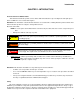
Introduction CHAPTER 1: INTRODUCTION Professional Service Manual Intent This manual is intended to provide service dealers with an introduction to proven diagnostic and repair procedures for MTD P71 series vertical shaft engines. Disclaimer: The information contained in this manual is correct at the time of writing. Both the product and the information about the product are subject to change without notice.
P71 Series Vertical Shaft Engines • Be prepared in case of emergency: ! CAUTION Keep a fire extinguisher nearby Keep a first aid kit nearby Keep emergency contact numbers handy • Replace any missing or damaged safety labels on shop equipment. • Replace any missing or damaged safety labels on equipment being serviced. • Grooming and attire: ! WARNING Do not wear loose fitting clothing that may become entangled in equipment. Long hair should be secured to prevent entanglement in equipment.
Introduction Fasteners • Most of the fasteners used on the MTD engine are metric. Some are fractional inches. For this reason, wrench sizes are frequently identified in the text, and measurements are given in U.S. and metric scales. • If a fastener has a locking feature that has worn, replace the fastener or apply a small amount of releasable thread locking compound such as Loctite® 242 (blue). • Some fasteners, like cotter pins, are single-use items that are not to be reused.
P71 Series Vertical Shaft Engines MTD Vertical Engine Model Designators 1P61MUA Starter/Alternators 1=Recoil start 2=Electric start (12V) 3=E. start/alt. 18W 4=E. start/alt. 3A/5A 5= AutoChoke/ Recoil 6= AutoChoke/Electric Start 7= AutoChoke/Electric Start/Alt Change Compliance U H C 0 (Zero) L G T Y W P= Vertical (1 cyl.) Q= Vertical (2 cyl.) T= Vertical (1 cyl.) Major Revision Bore Dia. (mm) X= Vertical (1 cyl.) United States (50 State) Europe California 49 State 49 State - Special U.S.
Introduction Model and serial number The model and serial number can be found on a white sticker with a bar code. The sticker is located behind the dipstick. See Figure 1.1. Model /serial number Dipstick Figure 1.1 NOTE: The serial number will always start with the model number. Maintenance The recommended maintenance intervals listed in this manual are a guideline. They are adjustable for local conditions.
P71 Series Vertical Shaft Engines Spark plugs The information in this manual applies to the MTD engine. Some basic principles may apply to engines produced by other manufacturers. As the saying goes “an ounce of prevention is worth a pound of cure”. The same can be said about preventive maintenance on outdoor power equipment. By changing the spark plug and oil at recommended intervals many failures can be avoided.
Introduction Air filter To remove/replace the air filter: 1. Rotate the air filter housing counter clockwise, approximately a quarter turn. See Figure 1.3. 2. Pull the housing off of the engine. 3. Remove the air filter and foam pre-cleaner. Figure 1.4. 4. Inspect the air filter and foam pre-cleaner. Figure 1.3 See NOTE: If a foam air pre-cleaner is dirty, but not in bad of condition, it can be cleaned and reused.
P71 Series Vertical Shaft Engines Oil type and capacity The recommended oil for MTD engines is an SAE 30 oil with an SM API rating or better. The oil capacity is 17.020.3 fl.oz (0.5-0.6 liters). • Check the oil level daily and change the oil more frequently in severe operating conditions such as high ambient temperature, dusty conditions, or high load use in exceptionally thick grass. • Synthetic oil is a suitable alternative, but it does not extend service intervals.
Introduction To check the oil: Fully seat the dip stick before reading it 1. Twist and remove the dipstick from the engine. 2. Clean the oil off of the tip of the dipstick. 3. Re-insert the dipstick and turn it until it is fully seated to get the oil level reading. See Figure 1.5. 4. The oil level is determined by the highest point on the dipstick that is completely covered with oil. Figure 1.
P71 Series Vertical Shaft Engines Changing the oil NOTE: If the engine has been running, allow the engine to cool before doing any maintenance work. NOTE: The oil should be changed after the first 5 hours of operation and every 50 hours there after. There are three methods of changing the oil. The application the engine is mounted to will determine which method to use: NOTE: There are four ways to drain the oil out of the P71 series of engines: • Drain plug in the bottom of the sump.
Introduction Tip the engine and application over A. Drain the fuel from the fuel tank into an approved container B. Remove the air filter. NOTE: Any time the engine is tipped, the fuel inside the carburetor will leak out into the air filter. C. Place an approved oil drain pan on the ground. D. Lean the application over on to the muffler side of the engine. E. Leave the application in this position until all of the oil has drained out. F. Tip the application back to its normal operating position.
P71 Series Vertical Shaft Engines Fuel system What you should know about fuel. Most of the fuel presently available in North America is oxygenated to some extent. This is commonly done through the addition of ethanol. Most engines offered for sale on outdoor power equipment in the North American markets are designed to tolerate no more than 10% ethanol by volume Ethanol is hygroscopic, meaning it absorbs water. If left exposed to air, it will draw water out of the air.
Introduction Valve lash Valve lash is the clearance between the top of the valve stem and the rocker arm. The valve lash should be checked after the first 25 hours of use and every 100 hours after that. Valve lash can be checked and adjusted using the following steps:. High tension lead Muffler Spark plug 1. If the engine has been run, allow it to cool thoroughly. Position the mower for easy access to the cylinder head. 2.
P71 Series Vertical Shaft Engines 6. Check valve lash between each valve stem and rocker arm using a feeler gauge. 7. Intake valve lash (top valve) should be 0.004” 0.006” (0.10 - 0.15 mm). See Figure 1.13. 0.005” feeler gauge Figure 1.13 8. Exhaust valve lash (bottom valve) should be 0.006” - 0.008” (0.15 - 0.20 mm). See Figure 1.14. 9. Use a 3 mm hex key to loosen the jam set screw, and a 14mm wrench to adjust the rocker arm fulcrum nut. See Figure 1.14. 10.
Introduction Exhaust system The exhaust system is a frequently overlooked component of an engine. It is important to make sure the muffler is in good condition and free of blockage. NOTE: A blocked muffler will result in poor performance. If a muffler is completely blocked, the engine may not start. Cleaning the engine 1. To maintain a proper operating temperature and to keep the equipment looking good, all debris should be removed from the engine. 2.
P71 Series Vertical Shaft Engines Useful Engine Specifications Description SAE Metric Engine displacement 11.9 cubic inch 195cc Spark plug gap 0.024” - 0.031” 0.6 - 0.8 mm Spark plug torque 177 - 221 in lbs 20 - 25 Nm Ignition module air gap 0.004” - 0.020” 0.10 - 0.50 mm Intake valve lash 0.004” - 0.006” 0.10 - 0.15 mm Exhaust valve lash 0.006” - 0.008” 0.15 - 0.20 mm Oil capacity 20 oz 0.
BASIC TROUBLESHOOTING CHAPTER 2: BASIC TROUBLESHOOTING Definitions Troubleshooting - The act of gathering information by preforming tests and direct observations. Diagnosis - Developing and testing theories of what the problem is, based on the information gathered in troubleshooting. Introduction Diagnosing an engine is an art form that is built upon several factors. First and most importantly is a good understanding of how the engine works. The second is skills that have been honed by experience.
P71 Series Vertical Shaft Engines IV. Unusual exhaust tone There are tools that the technician can use in order to define the problem, such as: 1. Interview the customer. 1a. Get a good description of their complaint. 1b. If it is an intermittent problem, verify what conditions aggravate the problem as best as possible. 1c. Get an accurate service history of the equipment. 1d. Find out how the customer uses and stores the equipment. 2. Direct observation: 2a.
BASIC TROUBLESHOOTING Identify factors that could cause the problem This is the second step in the troubleshooting process. 1. Crankshaft will not turn. A. Starter not working. This can be an electrical failure or a mechanical failure. The likely suspects are: I. A dead battery. II. A bad ground III. A failure in the electrical circuit. IV. A failure of the starter itself. B. Engine in a bind (external - attachment jammed).
P71 Series Vertical Shaft Engines I. Run the engine with a spark tester in-line between the spark plug wire and the spark plug or use an oscilloscope and see if the spark goes away at the same time the engine dies. II. Check choke operation. a. Black smoke? b. Wet plug? III. Prime test immediately after engine dies. If it restarts, this may indicate a problem with fuel flow to the carburetor. Check the gas cap, fuel line, fuel filter, and the float in the carburetor. 3b. Runs with low power output. I.
BASIC TROUBLESHOOTING V. Makes unusual smoke when running a. Black smoke, usually heavy, usually indicates a rich air fuel mixture • Not enough air: air flow blockage or a partially closed choke. • Too much fuel: carburetor float or float valve stuck or metering / emulsion issues with the carburetor. b. White smoke, usually heavy • Oil in muffler, usually the result of improper tipping. The engine will “fog” for a minute or so, then clear-up on its own. • Massive oil dilution with gasoline.
P71 Series Vertical Shaft Engines chirping noise. • Confirm with a compression test and leak-down test. e. Unusual exhaust tone Splashy or blatty • Splashy idle usually indicates a slight rich condition. • May indicate an exhaust blockage, usually slightly muffled. Backfire • On over-run: unburned fuel igniting past exhaust valve. Mixture not burning completely in combustion chamber. It may be too rich or it may be spark-plug or ignition problem.
BASIC TROUBLESHOOTING Repairing the problem The third step in the troubleshooting process is to repair the problem. This step consists of: A. Form a diagnosis by using all of the information gathered from the troubleshooting that was performed. B. Physically perform the repair. The fourth, and hopefully final, step in the troubleshooting process is the follow through. This step consists of: A. Thoroughly test the repaired equipment: confirming that the initial diagnosis was correct.
P71 Series Vertical Shaft Engines Prime test To perform a prime test: 1. Prime the engine through the carburetor throat using a squirt bottle, filled with clean fresh gasoline. 2. Make sure the throttle is in the run position. 3. Attempt to start the engine. 4. If the engine starts and runs long enough to burn the prime, the problem is effectively isolated to the fuel system. Proceed to Chapter 4: The Fuel System and Governor. 5.
BASIC TROUBLESHOOTING 6. Attach the leak down tester to an air supply of 90 psi. 7. Adjust the tester until the gauge’s needle is pointing to the set position. 8. Connect the tester to the adapter. NOTE: If the engine rotates it was not at top dead center. 9. Check the reading on the gauge.
P71 Series Vertical Shaft Engines Compression test To perform a compression test: NOTE: Compression should be in the range of 55 - 80 PSI (3.8 - 5.5 Bar). • Disconnect the high-tension lead from the spark plug and ground it well away from the spark plug hole. • Remove the spark plug using a 13/16” or 21mm wrench. A flexible coupling or “wobbly” extension may help. • Pull the starter rope several times to purge any fuel or oil from the combustion chamber. NOTE: Air compresses readily, liquid does not.
BASIC TROUBLESHOOTING PCV testing The PCV (Positive Crankcase Ventilation) valve is located in the engine block and allows the crankcase pressure to escape. Leakage and blockage are the two failure modes for a PCV system. Either mode will cause crankcase pressure to build-up, though the effects of a blocked PCV are generally more dramatic. Increased case pressure will result in oil entering the combustion chamber. NOTE: The PCV chamber is vented to the carburetor throat through a molded rubber hose.
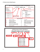
P71 Series Vertical Shaft Engines Troubleshooting flow charts Ignition Troubleshooting Engine runs erratically or shuts off, restarts Engine will not start Check for spark Spark No Spark Replace spark plug Check for the correct spark plug Check flywheel and key for damage or sheared key Set proper air gap on ignition module Test ignition module for intermittent or weak spark Check electric starter and battery if applicable Isolate engine from equipment and repeat test Spark Equipment problem, che
BASIC TROUBLESHOOTING Engine Operation Problems ENGINE KNOCKS OVERHEATS Associated equipment loose or improperly adjusted Excessive engine loading Check for excessive carbon in combustion chamber Low oil level or wrong viscosity oil Loose flywheel examine key, key way and proper flywheel nut torque Cooling air flow obstructed or clogged cooling fins Ignition timing or incorrect spark plug Carburetor improperly adjusted or improper RPM setting* Loose or worn connecting rod Ignition timing or inc
P71 Series Vertical Shaft Engines Engine Operation Problems EXCESSIVE OIL CONSUMPTION Oil level above full Wrong viscosity oil Excessive engine speed Engine cooling fins dirty causing overheating Breather damaged, dirty or improperly installed SURGES OR RUNS UNEVENLY Fuel cap vent obstructed Dirty carburetor or air filter Carburetor improperly adjusted Governor sticking, binding or improper RPM setting Carburetor linkage, shafts or shutters sticking or binding Intermittent spark, check ignition o
BASIC TROUBLESHOOTING Engine Operation Problems ENGINE MISFIRES ENGINE VIBRATES EXCESSIVELY Carburetor improperly adjusted Bent crankshaft Wrong or fouled spark plug Attached equipment out of balance Valves sticking or not seating properly Loose mounting bolts Ignition timing or incorrect spark plug If applicable counter balance not properly aligned Excessive carbon build up Improper Valve Lash Weak valve spring 31
P71 Series Vertical Shaft Engines Engine Operation Problems BREATHER PASSING OIL LACKS POWER Oil level too high Air intake obstructed Excessive RPM or improper governor setting Lack or lubrication or improper lubrication Damaged gaskets, seals or "O" rings Carburetor improperly adjusted Breather damaged, dirty or improperly installed Exhaust Obstructed Piston rings not properly seated or ring end gaps are aligned Improper valve lash Angle of operation too severe 32 Loss of compression (worn
AIR INTAKE SYSTEM CHAPTER 3: AIR INTAKE SYSTEM Air filter To remove/replace the air filter: 1. Rotate the air filter housing counter clockwise, approximately a quarter turn. See Figure 3.1. 2. Pull the housing off of the engine. Figure 3.1 3. Remove the air filter and foam pre-cleaner. See Figure 3.2. 4. Inspect the air filter and foam pre-cleaner. Air filter NOTE: If a foam air pre-cleaner is dirty, but not in bad condition, it can be cleaned and reused.
P71 Series Vertical Shaft Engines Carburetor removal/replacement To remove/replace the carburetor: 1. Remove the shroud by following the procedures described in Chapter 6: Starters. NOTE: Replace the fuel cap to minimized fuel spillage. 2. Remove the air filter by following the procedures described in the previous section of this chapter. 3. Remove the two screws that hold the air filter base to the carburetor using a T-25 torx driver. See Figure 3.3. 4. Remove and discard the air filter base gasket.
AIR INTAKE SYSTEM Throttle linkage 7. Mark the hole that the throttle linkage is inserted into with a paint pen or marker. See Figure 3.6. 8. Remove the two mounting nuts and bolts that hold the carburetor to the intake manifold. See Figure 3.6. 9. Disconnect the choke rod. 10. Disconnect the throttle linkage. 11. Disconnect the fuel line. 12. Drain the fuel into an approved container. 13. Remove the fuel line from the fuel tank and discard it. Paint mark Mounting nuts Figure 3.
P71 Series Vertical Shaft Engines Intake manifold To avoid personal injury or property damage, use extreme care in handling gasoline. Gasoline is extremely flammable and the vapors are explosive. Serious personal injury can occur when gasoline is spilled on yourself and/or your clothes which can ignite. Wash your skin and change clothes immediately ! WARNING To remove/replace the intake manifold: 1. Remove the carburetor by following the procedures described in the previous section. 2.
FUEL SYSTEM AND GOVERNOR CHAPTER 4: THE FUEL SYSTEM AND GOVERNOR The function of the fuel system is to store fuel, mix the fuel with air in the correct ratio and deliver it to the intake port. The fuel system consists of the following components: • Fuel lines • Fuel filter • Fuel tank • Vacuum lines • Charcoal canister • Carburetor and insulator block NOTE: When working on the fuel systems, look at the whole system. A problem will rarely be isolated to one component.
P71 Series Vertical Shaft Engines Inspecting the fuel NOTE: Fuel is the maintenance item most often overlooked by consumers. A lot of fuel systems problems are caused by gas that is out of date or fuel with too much alcohol in it. When inspecting the fuel: • Look for water. • Look for dirt. • Look for discoloration. • Sniff carefully to see if it smells like varnish or kerosene. • Save the fuel to show to customer. • Look for oil in the fuel. • Test the fuel for alcohol content.
FUEL SYSTEM AND GOVERNOR Fuel filter A dirty fuel filter can result in a lean run condition. The fuel filter should be replaced every 100 hours. To replace the fuel filter: NOTE: The fuel filter is located inside the fuel tank nipple. See Figure 4.4. 1. Siphon the fuel out of the fuel tank and dispose of the fuel in a safe and legal manner 2. Squeeze the tabs on the fuel line clamps and slide them away from the filter. 3. Carefully slide the fuel line off of the fuel tank nipple.
P71 Series Vertical Shaft Engines The fuel tank When working around the fuel system, do not bring any sources of heat, spark, or open flame near the work area. ! WARNING To remove the fuel tank: 1. Siphon the fuel out of the fuel tank into an approved container. 2. Disconnect the fuel line from the tank. 3. Remove the oil dipstick. 4. Remove the engine cover. 5. Remove the 3 nuts that hold down the shroud. See Figure 4.5. Nuts Figure 4.5 Tether 6.
FUEL SYSTEM AND GOVERNOR Evaporative (EVAP) emissions system Charcoal canister Vacuum line NOTE: All gasoline powered engines built on or after January 1, 2012 must meet Phase III emissions. Phase III emissions requires that the engine have an evaporative emissions system to limit the amount of fuel vapors that escape into the atmosphere. NOTE: Also all fuel caps must be tethered to the fuel tank as part of the EPA tier III emissions.
P71 Series Vertical Shaft Engines Troubleshooting the EVAP system Symptom Cause Fuel leaking from the carburetor throat or vents A blockage in the charcoal canister or between the canister and the tank. Engine runs rich • A blockage in the line between the charcoal canister and the carburetor insulator plate. Engine runs lean • Wrong fuel cap installed. • Leak in the vacuum lines. • Raw gasoline in the charcoal canister (plugged vent). • The charcoal canister is saturated.
FUEL SYSTEM AND GOVERNOR Autochoke Choke These engines are equipped with a temperature compensating auto choke. The autochoke system is similar to the old style air vane governors. When the engine is at rest a spring holds the choke in the closed position. See Figure 4.11. closed Temperature compensator Figure 4.11 When the engine starts, the air flow from the flywheel fan pushes on an air vane. The air vane in turn moves the choke lever, opening the choke. See Figure 4.12.
P71 Series Vertical Shaft Engines To remove/replace the air vane: 1. Remove the fuel cap and tether by unscrewing them. See Figure 4.6. 2. Remove the fuel tank nut. 3. Remove the screw that holds the fuel tank to the shroud using a 10 mm wrench. 4. Remove the engine cover. 5. Lift the shroud enough to gain access to the charcoal canister. 6. Disconnect the fuel tank vacuum line from the canister. 7. Slide the tank out of the shroud. 8.
FUEL SYSTEM AND GOVERNOR Carburetors Troubleshooting the carburetor is a process of elimination. If everything else on the engine checks out, the carburetor is probably bad. NOTE: It is important to perform a compression or leak down test before condemning a carburetor. An engine can have a borderline compression reading and not create enough of a vacuum to draw in a sufficient fuel/air charge.
P71 Series Vertical Shaft Engines Disassembly and rebuilding the carburetor 1. Clamp off the fuel line to prevent fuel spillage and disconnect it from the carburetor nipple 2. Drain the fuel into an approved container. 3. Remove and discard the fuel line. 4. Remove the carburetor by following the steps described in Chapter 3: Air Intake and Filter. 5. Remove the bowl screw using a 10mm wrench. See Figure 4.17.
FUEL SYSTEM AND GOVERNOR 8. Remove the main jet by using a narrow-shank straight blade screwdriver. See Figure 4.20. NOTE: Fuel enters the central column through a port about 1/2” (1cm) from the bottom, to help prevent the ingress of any residue in the bottom of the bowl. NOTE: The orifice in the main jet meters fuel into the central column. Main jet Figure 4.
P71 Series Vertical Shaft Engines 15. Adjust the top no-load speed by slightly bending the bracket that the governor spring connects to. The bracket is visible under the air filter. See Figure 4.23. Increase spring tension to increase engine speed Governor spring Bracket Figure 4.
FUEL SYSTEM AND GOVERNOR Governor arm To remove the governor arm from the governor shaft: Nuts 1. Siphon the fuel out of the fuel tank into an approved container. 2. Remove the oil dipstick. 3. Remove the engine cover. 4. Remove the 3 nuts that hold down the shroud. See Figure 4.25. 5. Remove the air filter by following the procedures described in Chapter 3: Air Intake System 6. Disconnect the purge hose from the air filter base. See Figure 4.26. 7.
P71 Series Vertical Shaft Engines To install the governor arm: 1. Rotate governor shaft counter clockwise until it stops. 2. Attach the throttle linkage and governor spring. 3. Position the governor arm over the governor shaft so that it is holding the throttle plate in the wide open position. See Figure 4.28. NOTE: There is a hairpin clip that keeps the governor shaft from sliding into the engine. It may be necessary to hold the shaft while sliding the arm on to prevent it from going into the engine.
FUEL SYSTEM AND GOVERNOR Governor shaft To remove or replace the governor shaft: Hairpin clip 1. Remove the engine from the unit. 2. Remove the governor arm by following the procedures described in the governor arm section of this chapter. 3. Remove the sump by following the steps described in Chapter 10: Disassembly. 4. Remove the hair pin clip from the governor shaft. See Figure 4.29. 5. Remove the flat washer. See Figure 4.30. 6.
P71 Series Vertical Shaft Engines 7. Remove the governor shaft seal. See Figure 4.32. Governor shaft seal Figure 4.32 8. Slide the governor shaft into the engine block from the inside of the engine. 9. Carefully slide a new seal over the governor shaft and seat using a 1/4” deep well socket. See Figure 4.33. Seal Cupped side NOTE: The cupped side of the seal faces the inside of the engine block. See Figure 4.33 inset. 10. Install the hair pin clip. Figure 4.33 11.
FUEL SYSTEM AND GOVERNOR Governor cup, gear and oil slinger The governor gear and cup are driven by the oil slinger gear. Rib NOTE: The governor gear and cup are not serviceable. To remove/replace the oil slinger gear: 1. Remove the engine from the unit. 2. Remove the sump by following the steps described in Chapter 10: Disassembly. 3. Remove the screw that hold the slinger gear plate to the sump using a 10mm wrench. See Figure 4.35. Oil slinger gear Figure 4.
P71 Series Vertical Shaft Engines 54
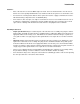
Lubrication CHAPTER 5: LUBRICATION Oil type and quantity The recommended oil for MTD engines is an SAE 30 oil with an SM API rating or better. The oil capacity is 17.020.3 fl.oz (0.5-0.6 liters). -4°F 14°F 32°F 50°F 68°F 86°F 104°F SAE 40 SAE 30 SAE 10W30/SAE 10W40 SAE 5W20 -20°C -10°C 0°C 10°C 20°C 30°C 40°C Oil Chart • If the oil is noticeably thin, or smells of gasoline, carburetor repair may be needed before the engine can be run safely.
P71 Series Vertical Shaft Engines Oil dipstick To check the oil: 1. Twist and remove the dipstick from the engine. 2. Clean the oil off of the tip of the dipstick. 3. Re-insert the dipstick and turn it until it is fully seated to get the oil level reading. See Figure 1.1. 4. The oil level is determined by the highest point on the dipstick that is completely covered with oil. Fully seat the dip stick before reading it Figure 1.
Lubrication Lubrication system MTD uses a splash lube system for it’s vertical shaft engines. The oil slinger gear has paddles on it that “splashes” oil around the inside of the engine. See Figure 5.4. Slinger gear Paddles Figure 5.4 The splashing action will also atomize or change the oil into a mist. There are two oil passages that run along the engine cylinder. The one just above the oil line is the oil supply passage. The oil mist will flow through this passage to the cylinder head.
P71 Series Vertical Shaft Engines PCV The PCV valve is located under the flywheel and allows the crankcase pressure to escape. The function and test procedures for the PCV is covered in Chapter 2: Basic Troubleshooting. PCV valve cover To service the PCV: 1. Remove the flywheel by following the steps described in the Chapter 7: Ignition System. 2. Remove PCV valve cover using a T-30 Torx driver. See Figure 5.7. Figure 5.7 3. Remove the foam insert. See Figure 5.8. Foam insert Figure 5.8 4.
Lubrication Notch 6. Insert a breather body, with the foam insert and a new O-ring. NOTE: There is a rib on the breather body that fits into a notch in the engine block. See Figure 5.10. Rib Figure 5.10 7. Install the PCV valve cover with a new gasket. Tighten the cover screws to a torque of 62 - 80 in lbs. (7 - 9 Nm). 8. Inspect the breather tubing for cracks, brittleness or signs of leaking. Replace the breather tube if any are found. 9.
P71 Series Vertical Shaft Engines 60
Starters CHAPTER 6: STARTERS Engine shroud removal To remove recoil assembly from the engine: 1. Remove the engine cover: NOTE: There are two types of engine covers: See Figure 6.1. • Full cover • Bib cover Bib Full Figure 6.1 Full cover 1a. Unsnap the front of the cover from the engine shroud. See Figure 6.2. 1b. Unhook the rear of the cover from the shroud. Bib cover 1a. Using a thin, flat blade push in the front tab of the bib cover enough to unsnap it from the shroud. 1b.
P71 Series Vertical Shaft Engines 2. Remove the oil dipstick. 3. Remove the 3 nuts that hold down the shroud. See Figure 6.3. Nuts Figure 6.3 4. Remove the air filter by following the procedures described in Chapter 3: Air Intake System 5. Disconnect the purge hose from the air filter base. See Figure 6.4. 6. Lift the shroud and fuel tank as one assembly high enough to clear the engine and set them beside the engine.
Starters Starter Cup Starter cup 1. Remove the recoil starter by following the procedures described int the recoil starter section of this chapter. 2. Inspect the inside of the starter cup. See Figure 6.6. NOTE: If the starter was failing to engage the flywheel, and the edges of the teeth inside the cup are rounded, replace the starter cup. NOTE: If the starter cup is replaced, the complete starter should be replaced as well, to prevent a repeat failure. Figure 6.6 3.
P71 Series Vertical Shaft Engines Starter Rope The most common failure mode for most recoil assemblies is a broken rope. See Figure 6.8. Starter cord knot NOTE: If the spring was not damaged when the recoil sprung back, it is possible to simply remove the remnants of the old rope. 1. Remove the starter by following the steps described earlier in this chapter. 2. Remove the old starter rope by prying out the starter cord knot and pulling the rope out with it. 3.
Starters Rope-return tension may be increased by winding the rope and pulley counter clockwise. NOTE: If starter rope tension needs to be adjusted, there is room between the recoil housing and the pulley to wind-on more tension. See Figure 6.11. 10. Install the starter and tighten the starter nuts to a torque of 80-106 in-lbs (9-12 Nm). Figure 6.
P71 Series Vertical Shaft Engines Starter pulley and recoil spring The recoil spring is nested within the starter pulley and both parts are assembled as a single part number. Pressure plate ! CAUTION Eye protection should be worn if the starter pulley is to be removed. Shoulder screw If damage is suspected, the recoil may be disassembled by: 1. Remove the starter by following the steps described earlier in this chapter. 2. Remove the shoulder screw and pressure plate using a 10 mm wrench.
Starters NOTE: If the spring is undamaged, but has been removed from the pulley, the spring may be re-wound. Engage the hook in the end of the spring with the slot in the outer lip of the recess that the spring fits in, and wind the spring into the recess in a counter-clockwise direction. NOTE: Evaluate the damage, including parts costs and local labor rates. In some parts of the country, it makes economic sense to replace the complete assembly, in other areas labor rates favor repair. 5.
P71 Series Vertical Shaft Engines Electric starter To remove/replace the electric starter: 1. Remove the shroud by following the procedures described in the Engine Shroud Removal section of this chapter. 2. Disconnect the starter harness. 3. Remove the two nuts the hold the starter cover to the starter, using an 8 mm wrench. See Figure 6.16. 4. Lift the cover off of the engine. Figure 6.16 Ring Gear 5. Remove the dip stick tube. 6.
Starters Starter Interlock Switch On engines equipped with an electric starter, there is a Starter Interlock Switch mounted on to the engine brake assembly. The interlock switch prevents power from reaching the electric starter unless the safety bail is depressed or the engine brake is released. Starter Interlock Switch Wires To remove/replace the Starter Interlock Switch: 1. Remove the Engine brake assembly by following the procedures described in Chapter 7: Ignition System. 2.
P71 Series Vertical Shaft Engines Schematic 70
Ignition System CHAPTER 7: IGNITION SYSTEM Troubleshooting the ignition system The purpose of the ignition system is to provide a spark in the combustion chamber at the proper time to efficiently ignite the fuel/air mixture. The steps in troubleshooting the ignition system are: 1. Examine the spark plug(s) by following the steps described in the spark plug section of this chapter. NOTE: It is convenient to check the compression when the spark plug is removed for examination. 2.
P71 Series Vertical Shaft Engines Troubleshooting the stop switch To test the stop switch: 1. Remove the engine shroud. 2. Unplug the wire from the spade terminal on the module. 3. Connect one probe of a Digital MultiMeter (DMM) to the lead disconnected from the module. 4. Connect the other probe to a good ground point on the engine. 5. Set the DMM to measure resistance. NOTE: The reading should be near zero when the bail released.
Ignition System Troubleshooting the flywheel To Troubleshoot the flywheel: 1. Remove the engine shroud. NOTE: Failure of the magnets in the flywheel is exceedingly rare. 2. Test the magnets by holding an item made of ferrous metal roughly 1/4” (.635cm) away from the magnets in the flywheel. See Figure 7.4. NOTE: It should be drawn to the flywheel. A wrench or screwdriver is suitable for this test. Magnets Figure 7.4 3. Check the polarity of the magnets using a magnetic compass or bar magnet.
P71 Series Vertical Shaft Engines Spark plug • The spark plug is a F6RTC, part #951-10292, gapped to 0.024” - 0.031” (0.6 - 0.8 mm). • Wear rate will vary somewhat with severity of use. If the edges of the center electrode are rounded-off, or any other apparent wear / damage occurs, replace the spark plug before operating failure (no start) occurs. Cleaning the spark plug • Cleaning the spark plug is not recommended. If the plug needs to be cleaned, replace it.
Ignition System Ignition module The ignition system is a capacitive discharge ignition system, contained in a single module. • The capacitive discharge has a three leg design. • The magneto is energized by the passing of a pair of magnets mounted in the flywheel. • Ignition timing is set by the location of the flywheel in relation to the crankshaft. Proper timing is maintained by a steel key. Module removal Remove the studs 1. Unplug the spark plug. 2.
P71 Series Vertical Shaft Engines Engine brake and stop switch (if equipped) NOTE: The stop switch and brake (for lawn mower applications) must be able to stop the blade from rotating within 3.0 seconds after the release of the safety bail, per ANSI B71.12003 standard. NOTE: The brake should be replaced when the thickness of the pad is less than 0.060” (1.524 mm) at the thinnest spot. To replace the brake assembly: 1. Disconnect and ground the spark plug wire. 2.
Ignition System Flywheel To remove the flywheel: 1. Remove the recoil assembly and the engine shroud by following the steps described in Chapter 6: Starter. 2. Lock the engine to prevent it from turning. 3. Loosen the flywheel nut until it is a couple of threads past the end of the crank shaft using a 19mm wrench. See Figure 7.13. Strap wrench Figure 7.13 NOTE: If equipped with an engine brake, clamp off the brake using a spring clamp. See Figure 7.14.
P71 Series Vertical Shaft Engines 5. Inspect the key, keyway, and tapered mating surfaces of the flywheel and crankshaft. See Figure 7.16. NOTE: If the key is damaged it must be replaced. If there is damage to the crankshaft key way, the engine must be short blocked because crankshafts are not available as a service part. Key flat parallel to the threads Taper IMPORTANT: The taper in flywheel and the on the crankshaft must be clean and dry.
Exhaust CHAPTER 8: EXHAUST Muffler The exhaust system is a frequently overlooked component of an engine. It is important to make sure the muffler is in good condition and free of debris and/or insects. NOTE: A blocked muffler will result in poor performance. If a muffler is completely blocked, the engine may not start. To remove/replace the muffler: Screw Shoulder bolts 1. Remove the engine shroud by following the procedures described in Chapter 6: Starters. 2.
P71 Series Vertical Shaft Engines Exhaust manifold To remove/replace the exhaust manifold: 1. Remove the muffler by following the procedures described in the previous section. 2. Remove the manifold screws using a 10 mm wrench. See Figure 8.3. 3. Clean the cylinder head and muffler of any residual gasket material. NOTE: The exhaust gasket is made of a graphite material. It will stick to the sealing surfaces when pressure is applied, tearing when pressure is relieved.
Cylinder head CHAPTER 9: CYLINDER HEAD The Cylinder head of the MTD engine can be removed without removing the engine from the application. To remove the cylinder head: NOTE: If possible, it is recommended that the machine be positioned on the bench so that the cylinder head is vertical for removal. See Figure 9.1. NOTE: This position provides easy access to most service points, yet prevents undue oil spillage. NOTE: Do not store the engine in this position for a long period of time.
P71 Series Vertical Shaft Engines 6. Loosen the jam screws and fulcrum nuts that secure the rocker arms using a 10mm wrench and a 14mm wrench. See Figure 9.3. 7. Pivot the rocker arms aside, or remove them completely, and remove the push rods. Jam screws NOTE: Once broken-in, the rocker arm should be kept with its corresponding valve. NOTE: The intake and exhaust push rods are identical and interchangeable.
Cylinder head 15. Position the cylinder head on the engine block. 16. Install the 5 head bolts, and tighten them to a torque of 221 - 239 in lb. (25 - 27 Nm) in 89 in lb (10 Nm) steps. See Figure 9.6. 17. Insert the push rods. 18. Install the rocker arms. Adjust the valve lash by following the steps described in Chapter 1: Introduction. 19. Install a new intake manifold gasket. 20. Figure 9.6 Install the intake manifold screws and tighten the support stud nut. 21.
P71 Series Vertical Shaft Engines Valves Valves and valve parts, like springs and keepers, are not available as service parts. The valves and valve seats can be serviced by grinding and lapping or the head can be replaced. Depending on local machine and labor costs, it is probably more economical to replace the cylinder head versus servicing the valves. To service the valves: NOTE: Servicing valves during the warranty period will void the warranty.
Cylinder head 5. Inspect the valve seat. See Figure 9.9. • Valve seats are 46 degrees. NOTE: This engine does not have the standard 3 angle cut. Seat angle is 46o 0.043-.050” • Seat width should be 0.044” - 0.054” (1.13 - 1.38 mm). NOTE: The valve seat can be ground to clean it up as long as the finished seat is within the tolerances listed above. Figure 9.9 6. Inspect the valve stem. See Figure 9.10. 7. Inspect the valve springs. NOTE: Valve spring free length should be 1.302” - 1.362” (33.
P71 Series Vertical Shaft Engines Push rod guides NOTE: The push rod guides are a wear item. On extreme cases, the guides can wear to a point that the push rods slip out from under the rocker arms. To remove/replace the push rod guides: 1. Disconnect and ground the spark plug high tension lead. 2. Remove the engine shroud by following the procedures described in Chapter 6: Starters 3. Remove the spark plug using a 13/16” or 21mm wrench. 4.
Crankshaft, piston and connecting rod CHAPTER 10: CRANKSHAFT, PISTON AND CONNECTING ROD There are a a few different paths that can be followed when disassembling an engine. This chapter will cover the removal of components in one order, but it is written so that the technician can jump around to the component being removed. The first step to disassemble the engine is to remove the engine from the application by following the steps described in the service manual for that particular application.
P71 Series Vertical Shaft Engines 16. Remove the sump bolts using a 10mm wrench. 17. Carefully slide the sump off of the crank shaft. See Figure 10.2. Figure 10.2 18. Remove the camshaft. See Figure 10.3. NOTE: Align the timing marks to allow easier removal of the cam shaft and to help protect the compression relief from damage. Cam shaft Timing marks NOTE: A paint pen can be used to fill in the timing marks for better visibility. Compression relief Figure 10.3 19. Remove the valve tappets.
Crankshaft, piston and connecting rod Place a match mark here NOTE: Match mark the connecting rod cap and the connecting rod so that they can be reassembled in the proper orientation. 20. Remove the connecting rod cap using a 7 mm wrench. See Figure 10.5. Remove the connecting rod bolts Figure 10.5 Connecting rod NOTE: Rotating the crank shaft after the connecting rod bolts are removed will help to separate the connecting rod from the cap. See Figure 10.6. Figure 10.6 21.
P71 Series Vertical Shaft Engines 23. Remove the crank shaft. See Figure 10.8. Lift up on crank shaft Figure 10.
Crankshaft, piston and connecting rod Crank shaft inspection Bearing contact area 1. Inspect the crank shaft journals for galling, scoring, pitting or any other form of damage. 2. Measure the journals at the bearing contact points using a vernier caliper or a micrometer. See Figure 10.9. 3. Inspect the crank pin for galling, scoring, pitting or any other form of damage. 4. Measure the crank pin using a vernier caliper or a micrometer. See Figure 10.10. Figure 10.9 Crank pin Figure 10.10 5.
P71 Series Vertical Shaft Engines Piston Inspection 1. Separate the piston from the connecting rod: 1a. Remove one of the piston pin clips. See Figure 10.11. 1b. Push the piston pin out of the piston. 1c. Slide the connecting rod out of the piston. Piston pin clip Figure 10.11 Piston ring 2. Clean the piston and remove all carbon from the rings and ring groves. 3. Insert one ring into the cylinder. Push it down about one inch from the top. See Figure 10.12. 4.
Crankshaft, piston and connecting rod NOTE: The top ring is symmetrical and the middle ring has a tapered profile. The larger radius of the middle ring should face the crankshaft. See Figure 10.14. Top ring Middle ring 3 piece oil ring Figure 10.14 Piston ring end gap stagger Top ring NOTE: The piston ring end gaps need to be staggered 90o apart. See Figure 10.15. Middle ring Oil ring Figure 10.15 7.
P71 Series Vertical Shaft Engines 8. Inspect the piston pin for galling, scoring, pitting or any other form of damage. 9. Measure the piston pin using a vernier caliper or a micrometer. See Figure 10.17. Figure 10.17 Connecting rod inspection 1. Inspect the connecting rod for cracks or any signs of damage. 2. Install the rod cap and tighten to a torque of 102 111 in-lbs (11.5-12.5 Nm) 3.
Crankshaft, piston and connecting rod Cylinder inspection Measure the cylinder bore 1. Clean and inspect the cylinder, inside and out. NOTE: If there is any sign of damage, especially cracked cooling fins, short block the engine. NOTE: Take two measurements of the cylinder bore 90 degrees apart at the top, bottom and middle of the cylinder. See Figure 10.20. Figure 10.20 NOTE: The measurements can be made using telescoping gauges, inside micrometers or a cylinder bore dial indicator. See Figure 10.21.
P71 Series Vertical Shaft Engines Bearings There are two bearings to inspect; a plain bearing in the sump and a ball bearing in the cylinder block. To inspect the bearings: 1. Remove the sump and cylinder block oil seals using a seal puller. See Figure 10.22. Seal puller Cylinder block oil seal Figure 10.22 2. 3. Inspect the bearing surface for galling, scratches, metal transfer or any other signs of damage.
Crankshaft, piston and connecting rod Reassembly 1. Seal driver 2. Clean the cylinder 1a. Remove all gasket material from all mating surfaces. 1b. Clean the cylinder and sump. Oil seals 2a. Install a new oil seal in the cylinder block. See Figure 10.24. NOTE: A piece of 1” schedule 40 PVC pipe can be used as a seal driver. 2b. Install a new seal in the sump. Figure 10.24 3. Seal protector Insert the crankshaft into the cylinder block bearing.
P71 Series Vertical Shaft Engines 4d. Tap the piston through the ring compressor into the cylinder using a wooden hammer handle. See Figure 10.27. Tap piston with hammer handle NOTE: Make sure the crankshaft journal is at BDC (bottom dead center) to prevent damage from the connecting rod. Figure 10.27 4e. Pre-lube the connecting rod with clean 10W30 motor oil or engine assembly lube. 4f. Install the connecting rod cap.
Crankshaft, piston and connecting rod 6. Cam shaft Install the cam shaft by: 6a. Pre-lube the cam shaft with clean 10W-30 motor oil or engine assembly lube. 6b. Rotate the crank shaft until the timing mark points to the tappets. 6c. Insert the cam shaft while aligning the timing marks. See Figure 10.30. Timing marks Compression relief Figure 10.30 Seal protector 7. If removed, install the governor arm by following the steps described in Chapter 4: Fuel systems and Governor. 8.
P71 Series Vertical Shaft Engines 9. Install the cylinder head by following the steps described in Chapter 9: Cylinder head. 10. Install the muffler by following the steps described in Chapter 8: Exhaust. 11. Install the flywheel and module by following the steps described in Chapter 7: Ignition system. 12. Install the blade brake, if equipped. 13. Install the fuel tank by following the steps described in Chapter 4: Fuel systems and Governor. 14.
Crankshaft, piston and connecting rod Engine specifications chart Specification Minimum in Displacement Bore Maximum mm in mm 11.9 cu. in (195 cc) 2.7953” Stroke 71.001 2.7957” 71.011 1.937” (49.2 mm) Module air gap 0.004” 0.10 0.020” 0.50 Spark plug gap 0.024” 0.60 0.031” 0.80 Intake valve lash 0.004” 0.10 0.006” 0.15 Exhaust valve lash 0.006” 0.15 0.008” 0.20 Valve seat angle Valve seat width 46o 0.044 1.13 Crankshaft end play 0.054 1.38 0.
P71 Series Vertical Shaft Engines Specification Minimum Maximum Intake lobe base circle diameter 0.3905 9.92 0.3905 9.92 Exhaust lobe rise 0.197 5.00 0.203 5.15 Exhaust lobe base circle diameter 0.3905 9.92 0.3905 9.92 Compression ring end gap 0.006” 0.15 0.010” 0.25 Scraper (second) ring end gap 0.006” 0.15 0.010” 0.25 Compression ring to land clearance 0.001” 0.02 0.002” 0.06 Scraper (second) ring to land clearance 0.001” 0.02 0.002” 0.
Crankshaft, piston and connecting rod Fastener S.A.E.
P71 Series Vertical Shaft Engines 104
Failure Analysis CHAPTER 11: FAILURE ANALYSIS A properly maintained engine will provide years of service. Occasionally an engine will fail. An important part of working on engines is being able to recognize the root cause of engine failures. Was it something the customer did? Was it a manufacturing defect? Did the engine just wear out? All of these questions need to be answered. Identifying and eliminating the cause of the failure is the only way to prevent recurring failures.
P71 Series Vertical Shaft Engines 5. When particles enter the combustion chamber, the up and down motion of the piston grinds the particles into the side of the cylinder walls and damages the cylinder wall, piston and piston rings. 6. This can be identified by the scoring along the vertical axis of the piston and cylinder wall or the cross hatch on the cylinder wall being worn off.
Failure Analysis 8. Because the oil suspends the particles, the engine components that are immersed in oil will show definite signs of abrasive ingestion especially around the connecting rod and main bearing journals. See Figure 11.5. NOTE: Abrasives that are trapped in the oil will cause the lower portion of the combustion chamber to wearing more than the upper portion. NOTE: Wear of only one bearing surface on a new engine could be a sign of a manufacturing defect. Figure 11.
P71 Series Vertical Shaft Engines Insufficient lubrication The bearing surfaces in an engine are not smooth. The machining processes used to make the engine parts, leave little peaks and valleys that are only visible under a microscope. These peaks are called asperities. As the engine breaks in, the asperities break off leaving plateaus that become the bearing surface. The valleys become reservoirs for the lubricant.
Failure Analysis Discoloration 3. Metal transfer is the primary indicator that the film of oil between two engine parts has been violated. If the damage is localized, a general failure of the lubrication system is probably not the cause. As an example: a piston skirt shows metal transfer to the cylinder wall. The connecting rod and wrist pin show some signs of excessive heat. The main bearings and camshaft are not damaged. This would indicate that the problem was probably related to cylinder temperature.
P71 Series Vertical Shaft Engines Engine Over-speed The MTD engine is designed for a maximum speed of 3300 rpm. When the governor is unable to control the engine rpm, the engine can accelerate past the safe maximum speed. When an engine runs beyond its designed speed, a few things happen: 1. As the piston moves up and down in the cylinder, it builds momentum. The higher the RPMs the more momentum produced by the pistons. As the momentum builds, the connecting rods will start to stretch.
Failure Analysis Overheated The MTD engines are air cooled engines. Because of this, cleanliness of the engine is very important to the life of the engine. Dirt, grass and sludge all form an insulating layer on the engine. This will trap the heat in the engine and cause it to over heat. Discolored rockers As metal parts heat up enough to change their properties, they will take on a yellowish or blue cast. As oil is heated to the point that it evaporates, black deposits are left behind.
P71 Series Vertical Shaft Engines Mechanical Breakage/ Wear Sometimes an engine fails because a part breaks. There are generally three causes of a broken part, outside of the previously discussed engine failures. They are abuse, wear, and manufacturing defects. Bent blade A very common sign of an abused engine is a bent crank shaft. Crankshafts bend when they, or something bolted to them hits something. A prime example of this is when a mower blade hits a rock. See Figure 11.11.
MTD Products Inc - Product Training and Education Department FORM NUMBER - 769-09340 9/2013