Professional Shop Manual 61, 65 and 70 Series Vertical Shaft Engines NOTE: These materials are for use by trained technicians who are experienced in the service and repair of outdoor power equipment of the kind described in this publication, and are not intended for use by untrained or inexperienced individuals. These materials are intended to provide supplemental information to assist the trained technician.
Table of Contents Chapter 1: Introduction Professional Service Manual Intent ................................................................... 1 Safety .................................................................................................................1 Fasteners ...........................................................................................................3 Assembly instructions ........................................................................................
Chapter 4: The Fuel System and Governor Fuel Lines ........................................................................................................37 Inspect the fuel lines ........................................................................................37 Inspecting the fuel ............................................................................................37 Test fuel for alcohol .........................................................................................
Chapter 7: Ignition System Troubleshooting the ignition system ................................................................85 Troubleshooting the stop switch ......................................................................85 About the spark plug ........................................................................................91 Cleaning the spark plug ...................................................................................91 Inspection of the spark plug ..........................
IV
Introduction CHAPTER 1: INTRODUCTION Professional Service Manual Intent This manual is intended to provide service dealers with an introduction to proven diagnostic and repair procedures for MTD 61, 65 and 70 series vertical shaft engines. Disclaimer: The information contained in this manual is correct at the time of writing. Both the product and the information about the product are subject to change without notice.
61, 65 and 70 Series Vertical Shaft Engines • Be prepared in case of emergency: ! CAUTION Keep a fire extinguisher nearby Keep a first aid kit nearby Keep emergency contact numbers handy • Replace any missing or damaged safety labels on shop equipment. • Replace any missing or damaged safety labels on equipment being serviced. • Grooming and attire: ! WARNING Do not wear loose fitting clothing that may become entangled in equipment.
Introduction Fasteners • Most of the fasteners used on the MTD engine are metric. Some are fractional inches. For this reason, wrench sizes are frequently identified in the text, and measurements are given in U.S. and metric scales. • If a fastener has a locking feature that has worn, replace the fastener or apply a small amount of releasable thread locking compound such as Loctite® 242 (blue). • Some fasteners, like cotter pins, are single-use items that are not to be reused.
61, 65 and 70 Series Vertical Shaft Engines MTD Vertical Engine Model Designators 1P61MUA Starter/Alternators 1=Recoil start 2=Electric start (12V) 3=E. start/alt. 18W 4=E. start/alt. 3A/5A 5= AutoChoke/ Recoil 6= AutoChoke/Electric Start 7= AutoChoke/Electric Start/Alt Change Compliance U H C 0 (Zero) L G T Y W P= Vertical (1 cyl.) Q= Vertical (2 cyl.) T= Vertical (1 cyl.) Major Revision Bore Dia. (mm) X= Vertical (1 cyl.) United States (50 State) Europe California 49 State 49 State - Special U.
Introduction Model and serial number The model and serial number can be found on a white sticker with a bar code. The sticker is usually located between the dipstick and the muffler. See Figure 1.1. Model /serial number Dipstick Muffler Figure 1.1 NOTE: The serial number will always start with the model number. Maintenance The recommended maintenance intervals listed in this manual are a guideline. They are adjustable for local conditions.
61, 65 and 70 Series Vertical Shaft Engines Spark plugs The information in this manual applies to the MTD engine. Some basic principles may apply to engines produced by other manufacturers. As the saying goes “an ounce of prevention is worth a pound of cure”. The same can be said about preventive maintenance on outdoor power equipment. By changing the spark plug and oil at recommended intervals many failures can be avoided.
Introduction Air filter The main function of the air filter is to trap air borne particles before they reach the carburetor that can cause catastrophic internal engine damage. Paper-pleated element MTD vertical shaft engines are equipped with one of two different air filters. The first is a rectangular paper pleated filter that may or may not have a foam pre-cleaner. The second is an oval foam filter. See Figure 1.3.
61, 65 and 70 Series Vertical Shaft Engines Oil type and capacity The recommended oil for MTD engines is an SAE 10W-30 oil with an SM API rating or better. The oil capacity is 17.0- 20.3 fl.oz (0.5-0.6 liters). • Check the oil level daily and change the oil more frequently in severe operating conditions such as high ambient temperature, dusty conditions, or high load use in exceptionally thick grass. • Synthetic oil is a suitable alternative, but it does not extend service intervals.
Introduction NOTE: There are two types of dip sticks that can be found on MTD engines; a threaded dip stick that was used on older engines and a quarter turn dip stick that is used on engines currently being produced. See Figure 1.4. Threaded 1/4 turn Figure 1.4 To check the oil with a threaded dip stick: Dip stick 1. Twist and remove the dip stick from the engine. 2. Clean the oil off of the tip of the dipstick. 3. Re-insert the dipstick without threading it in to get the oil level reading.
61, 65 and 70 Series Vertical Shaft Engines Changing the oil NOTE: If the engine has been running, allow the engine to cool before doing any maintenance work. Siphon NOTE: The oil should be changed after the first 5 hours of operation and every 25 hours there after. There are three methods of changing the oil. The application the engine is mounted to will determine which method to use: Siphon the oil out through the dip stick tube A. Insert the siphon hose into the dip stick tube. See Figure 1.7. B.
Introduction Fuel system What you should know about fuel. Most of the fuel presently available in North America is oxygenated to some extent. This is commonly done through the addition of ethanol. Most engines offered for sale on outdoor power equipment in the North American markets are designed to tolerate no more than 10% ethanol by volume Ethanol is hygroscopic, meaning it absorbs water. If left exposed to air, it will draw water out of the air.
61, 65 and 70 Series Vertical Shaft Engines Fuel filter 1. Some of the early engines were equipped with a fuel filter placed between the fuel tank and the carburetor. See Figure 1.10. Fuel Filter Figure 1.10 2. Currently the engines are equipped with a fuel filter installed in the fuel tank where the fuel line connects. See Figure 1.11. New style Old style Figure 1.
Introduction Valve lash Valve lash is the clearance between the top of the valve stem and the rocker arm. The valve lash should be checked after the first 25 hours of use and every 100 hours after that. Valve lash can be checked and adjusted using the following steps:. 1. If the engine has been run, allow it to cool thoroughly. Position the mower for easy access to the cylinder head. 2. Disconnect the high-tension lead from the spark plug and ground it well away from the spark plug hole. 3.
61, 65 and 70 Series Vertical Shaft Engines 6. Check valve lash between each valve stem and rocker arm using a feeler gauge. 7. Intake valve lash (top valve) should be: See Figure 1.14. • “P70” series = 0.003” - 0.005” (0.08 - 0.12mm). • “P61, P65, and X65” series = 0.004” - 0.006” (0.10 - 0.15 mm) 0.004” feeler gauge Setting intake valve lash Figure 1.14 Setting exhaust valve lash 8. 9. Exhaust valve lash (bottom valve) should be: See Figure 1.15. • “P70” series = 0.005” - 0.007” (0.13 - 0.
Introduction Exhaust system The exhaust system is a frequently overlooked component of an engine. It is important to make sure the muffler is in good condition and free of blockage. NOTE: A blocked muffler will result in poor performance. If a muffler is completely blocked, the engine may not start. Cleaning the engine 1. To maintain a proper operating temperature and to keep the equipment looking good, all debris should be removed from the engine. 2.
61, 65 and 70 Series Vertical Shaft Engines 16
BASIC TROUBLESHOOTING CHAPTER 2: BASIC TROUBLESHOOTING Definitions Troubleshooting - The act of gathering information by preforming tests and direct observations. Diagnosis - Developing and testing theories of what the problem is, based on the information gathered in troubleshooting. Introduction Diagnosing an engine is an art form that is built upon several factors. First and most importantly is a good understanding of how the engine works. The second is skills that have been honed by experience.
61, 65 and 70 Series Vertical Shaft Engines IV. Unusual exhaust tone There are tools that the technician can use in order to define the problem, such as: 1. Interview the customer. 1a. Get a good description of their complaint. 1b. If it is an intermittent problem, verify what conditions aggravate the problem as best as possible. 1c. Get an accurate service history of the equipment. 1d. Find out how the customer uses and stores the equipment. 2. Direct observation: 2a.
BASIC TROUBLESHOOTING Identify factors that could cause the problem This is the second step in the troubleshooting process. 1. Crankshaft will not turn. A. Starter not working. This can be an electrical failure or a mechanical failure. The likely suspects are: I. A dead battery. II. A bad ground III. A failure in the electrical circuit. IV. A failure of the starter itself. B. Engine in a bind (external - attachment jammed).
61, 65 and 70 Series Vertical Shaft Engines I. Run the engine with a spark tester in-line between the spark plug wire and the spark plug or use an oscilloscope and see if the spark goes away at the same time the engine dies. II. Check choke operation. a. Black smoke? b. Wet plug? III. Prime test immediately after engine dies. If it restarts, this may indicate a problem with fuel flow to the carburetor. Check the gas cap, fuel line, fuel filter, and the float in the carburetor. 3b.
BASIC TROUBLESHOOTING V. Makes unusual smoke when running a. Black smoke, usually heavy, usually indicates a rich air fuel mixture • Not enough air: air flow blockage or a partially closed choke. • Too much fuel: carburetor float or float valve stuck or metering / emulsion issues with the carburetor. b. White smoke, usually heavy • Oil in muffler, usually the result of improper tipping. The engine will “fog” for a minute or so, then clear-up on its own. • Massive oil dilution with gasoline.
61, 65 and 70 Series Vertical Shaft Engines chirping noise. • Confirm with a compression test and leak-down test. e. Unusual exhaust tone Splashy or blatty • Splashy idle usually indicates a slight rich condition. • May indicate an exhaust blockage, usually slightly muffled. Backfire • On over-run: unburned fuel igniting past exhaust valve. Mixture not burning completely in combustion chamber. It may be too rich or it may be spark-plug or ignition problem.
BASIC TROUBLESHOOTING Repairing the problem The third step in the troubleshooting process is to repair the problem. This step consists of: A. Form a diagnosis by using all of the information gathered from the troubleshooting that was performed. B. Physically perform the repair. The fourth, and hopefully final, step in the troubleshooting process is the follow through. This step consists of: A. Thoroughly test the repaired equipment: confirming that the initial diagnosis was correct.
61, 65 and 70 Series Vertical Shaft Engines Prime test To perform a prime test: 1. Prime the engine through the carburetor throat using a squirt bottle, filled with clean fresh gasoline. 2. Make sure the throttle is in the run position. 3. Attempt to start the engine. 4. If the engine starts and runs long enough to burn the prime, the problem is effectively isolated to the fuel system. Proceed to Chapter 4: The Fuel System and Governor. 5.
BASIC TROUBLESHOOTING 7. Compare the results to the following chart. Leak-down Testing Results Symptom Possible cause Air escaping from the breather Worn cylinder or piston rings.
61, 65 and 70 Series Vertical Shaft Engines Compression test To perform a compression test: NOTE: Compression should be in the range of 55 - 85 PSI (3.8 - 5.9 Bar). • Disconnect the high-tension lead from the spark plug and ground it well away from the spark plug hole. • Remove the spark plug using a 13/16” or 21mm wrench. A flexible coupling or “wobbly” extension may help. • Pull the starter rope several times to purge any fuel or oil from the combustion chamber.
BASIC TROUBLESHOOTING PCV testing The PCV (Positive Crankcase Ventilation) valve is located in the engine block and allows the crankcase pressure to escape. Leakage and blockage are the two failure modes for a PCV system. Either mode will cause crankcase pressure to build-up, though the effects of a blocked PCV are generally more dramatic. Increased case pressure will result in oil entering the combustion chamber. NOTE: The PCV chamber is vented to the air filter through a molded rubber hose.
61, 65 and 70 Series Vertical Shaft Engines 28
AIR INTAKE SYSTEM CHAPTER 3: AIR INTAKE SYSTEM Air filter Paper-pleated element MTD vertical shaft engines are equipped with one of two different air filters. The first is a rectangular paper pleated filter that may or may not have a foam pre-cleaner. The second is an oval foam filter. See Figure 3.1. NOTE: There are four different air filter housings styles used on 61, 65 and 70 series engines: • Paper filer with a thumb screw door. • Paper filter with a snap fit door. • Oval foam filter housing.
61, 65 and 70 Series Vertical Shaft Engines Paper filter with a snap fit door To access the air filter: 1. Press down on both tabs See Figure 3.3.. 2. Swing down the filter door. 3. Remove the air filter. 4. Install the filter by following the previous steps in reverse order. Tabs Figure 3.3 Paper air filter housings Crankcase vent tube To remove a paper air filter housing: 1. Remove the air filter by following the steps described in the appropriate section above. 2.
AIR INTAKE SYSTEM Foam air filter To access the air filter: 1. Press in the tab on the air filter cover. See Figure 3.6. 2. Swing open the filter cover. See Figure 3.7. 3. Remove the air filter. 4. Install by following the above steps in reverse order. Press tab Figure 3.6 Figure 3.7 Foam air filter housing Filter mounting screw To remove the air filter housing: 1. Remove the air filter by following the steps described in the previous section. 2.
61, 65 and 70 Series Vertical Shaft Engines 4. Disconnect the crankcase vent tube. See Figure 3.9. 5. Disconnect the primer line. See Figure 3.9. 6. Lift away the filter housing. Primer line crankcase vent tube Figure 3.9 7. The primer can be removed from the air filter housing by squeezing together the two sets of barbs while pushing the primer out of the housing. See Figure 3.10. Squeeze the barbs together, then push Figure 3.
AIR INTAKE SYSTEM Carburetor Insulator To avoid personal injury or property damage, use extreme care in handling gasoline. Gasoline is extremely flammable and the vapors are explosive. Serious personal injury can occur when gasoline is spilled on yourself and/or your clothes which can ignite. Wash your skin and change clothes immediately ! WARNING To remove/replace the carburetor insulator: 1. Remove the air filter housing by following the previously described steps.
61, 65 and 70 Series Vertical Shaft Engines 2d. Rotate the throttle arm until it meets the idle speed screw, then pivot the carburetor slightly to disengage the 90 degree bend at the end of the governor rod. See Figure 3.14. Governor rod Throttle arm Figure 3.14 2e. Pivot the carburetor to disengage the Z-fitting on the end of the choke rod. See Figure 3.15. 2f. Unhook the stabilizer spring that takes-up the play between the governor arm, the governor rod, and the throttle arm on the carburetor.
AIR INTAKE SYSTEM Insulator Bowl vent channel 3. The insulator is sandwiched between two gaskets which are located between the carburetor and the cylinder head. See Figure 3.17. NOTE: The gaskets are different, and there is an orientation to the insulator. Gasket: Insulator to carburetor Gasket: insulator to cylinder head Figure 3.17 NOTE: On some engines, the insulator to cylinder head gasket is a graphite gasket/heat shield. See Figure 3.18.
61, 65 and 70 Series Vertical Shaft Engines 36
FUEL SYSTEM AND GOVERNOR CHAPTER 4: THE FUEL SYSTEM AND GOVERNOR The function of the fuel system is to store fuel, mix the fuel with air in the correct ratio and deliver it to the intake port. The fuel system consists of the following components: • Fuel tank • Fuel lines • Fuel filter • Carburetor and insulator block NOTE: When working on the fuel systems, look at the whole system. A problem will rarely be isolated to one component. Fuel Line The fuel line used by MTD is GREENBARTM.
61, 65 and 70 Series Vertical Shaft Engines Inspecting the fuel NOTE: Fuel is the maintenance item most often overlooked by consumers. A lot of fuel systems problems are caused by gas that is out of date or fuel with too much alcohol in it. When inspecting the fuel: • Look for water. • Look for dirt. • Look for discoloration. • Sniff carefully to see if it smells like varnish or kerosene. • Save the fuel to show to customer. • Look for oil in the fuel. • Test the fuel for alcohol content.
FUEL SYSTEM AND GOVERNOR The fuel filter The fuel filter is located in the fuel tank. It can be removed and cleaned with a can of carb cleaner or replaced. See Figure 4.4. New style Old style Figure 4.4 NOTE: On some early production engines, an in-line filter was used. See Figure 4.5. In-line filter Figure 4.
61, 65 and 70 Series Vertical Shaft Engines Fuel tank vent The fuel tank vent performs the important task of allowing air into the fuel tank. As fuel is being used by the engine, the fuel level in the tank drops. The dropping fuel level then creates a vacuum in the tank. If the fuel tank could not suck air through the vent, the vacuum would prevent the fuel from getting to the carburetor. The tank is vented through the cap. See Figure 4.6. Tank Cap liner / gasket Filter Cap Sleeve (mtg.
FUEL SYSTEM AND GOVERNOR The fuel tank There are three fuel tanks available for the 61, 65 and 70 series engines: • The original bolt through the center tank. • The charcoal canister tank. • The slanted neck tank. ! WARNING When working around the fuel system, do not bring any sources of heat, spark, or open flame near the work area. The original tank To remove the fuel tank: Screw and fender washer Screw 1. Drain the fuel out of the fuel tank into an approved container. 2.
61, 65 and 70 Series Vertical Shaft Engines 4. Remove the bottom screw using a 10mm wrench. See Figure 4.10. Remove this screw Figure 4.10 5. Remove the top two screws and remove the tank. See Figure 4.11. 6. Install the tank by following the previous steps in reverse order. 7. Test run the engine in a safe area before returning to service. Remove these screws Figure 4.11 Slanted neck tank To remove the fuel tank: 1. Drain the fuel out of the fuel tank into an approved container. 2.
FUEL SYSTEM AND GOVERNOR Charcoal canister 7. Lift the shroud enough to gain access to the charcoal canister. 8. Disconnect the fuel tank vacuum line from the canister. 9. slide the tank out of the shroud. 10. Install the fuel tank by following the previous step in reverse order. Figure 4.13 Evaporative (EVAP) emissions system Gasoline is made from the graduated distillation of crude oil. It consists of a multitude of individual hydrocarbons and has a boiling range of 86 - 410oF (30-210oC)1.
61, 65 and 70 Series Vertical Shaft Engines Charcoal canister system with the canister snapped into the tank This charcoal canister system consists of: • A charcoal canister • The fuel tank and cap • A roll over valve vent • A carburetor insulator. • Vacuum lines Roll over valve Charcoal canister Figure 4.15 This system operates as follows: 1. The gasoline evaporates, letting off vapors. 2. The vapors exit the fuel tank through the roll over valve vent.
FUEL SYSTEM AND GOVERNOR 5. When the engine is running, the vacuum inside the carburetor insulator is used to draw the vapors out of the charcoal canister, temporarily enriching the fuel/ air mixture, and is used in the combustion process. See Figure 4.18. Charcoal canister Figure 4.18 Charcoal canister system with the canister snapped into the shroud This charcoal canister system consists of: • A charcoal canister • The fuel tank and cap • Vacuum lines Vacuum lines Charcoal canister Figure 4.
61, 65 and 70 Series Vertical Shaft Engines Troubleshooting the EVAP system NOTE: Troubleshooting a charcoal canister fuel cap is the same as troubleshooting a non-EVAP system. Symptom Cause Fuel leaking from the carburetor throat or vents A blockage in the charcoal canister or between the canister and the tank. Engine runs rich • Raw gasoline in the charcoal canister. • A blockage in the line between the charcoal canister and the carburetor insulator plate. • Wrong fuel cap installed.
FUEL SYSTEM AND GOVERNOR Roll over valve vent To remove/replace the roll over valve: 1. Disconnect the vacuum line. See Figure 4.21. 2. Gently pry the roll over valve out of the fuel tank. See Figure 4.22. 3. Inspect the rubber grommet, replace if damaged. 4. With the grommet on the roll over valve, install the roll over valve by pressing it into the opening in the tank. See Figure 4.23. 5. Install the vacuum line. 6. Test run the engine in a safe area before returning to service.
61, 65 and 70 Series Vertical Shaft Engines Testing the roll over valve The roll over valve vent has two functions. The first function is to vent the tank and the second function is to close off the vent if the tank is inverted. Test the roll over valve by: 1. Remove the roll over valve by following the steps described above. 2. Connect a vacuum pump to the roll over valve. 3. Hold the roll over valve in an inverted position. 4. Apply a vacuum to the roll over valve. See Figure 4.24. 15 in.Hg.
FUEL SYSTEM AND GOVERNOR Charcoal canister To remove/replace the charcoal canister snapped into the tank: Remove the vacuum lines 1. Remove the fuel tank by following the steps described in the Charcoal canister fuel tank section of this chapter. 2. Remove the vacuum line that runs from the roll over valve to the charcoal canister. See Figure 4.26. 3. Unsnap the charcoal canister from the fuel tank. 4. Install the charcoal canister by following the previous steps in reverse order.
61, 65 and 70 Series Vertical Shaft Engines Manual Choke If the engine is equipped with a manual choke, the choke must be closed to start the engine and opened when the engine starts. This can be a source of starting issues with customers who are not familiar with manual chokes. The manual choke is operated by a pull knob at the carburetor or on the handle bar, depending on the application.
FUEL SYSTEM AND GOVERNOR Air flow When the engine starts, the air flow from the flywheel fan pushes on an air vane. the air vane in turn moves the choke lever, opening the choke. See Figure 4.31. Choke open Figure 4.31 1P61/1P65 Autochoke To remove/replace the air vane: NOTE: The choke linkage can be slightly bent to make adjustments if the choke is not opening or closing fully. Remove this screw 1. Remove the ignition module by following the steps described in Chapter 7: Ignition System. 2.
61, 65 and 70 Series Vertical Shaft Engines 1P70 Autochoke The 1P70 autochoke uses an air door that functions the same way as the air vane described earlier. NOTE: There is no choke linkage in this system, therefore there is no way to make adjustments for choke travel. To remove/replace the air door: 1. Remove the starter and blower housing by following the steps described in Chapter 6: Starters. NOTE: The air door is mounted to the underside of the blower housing. See Figure 4.34. Air door Figure 4.
FUEL SYSTEM AND GOVERNOR 4. To install the air door, turn the blower housing upside down. 5. Hold the air door in place while sliding in the rod. NOTE: Make sure the rod goes through all of the rod channels. See Figure 4.37. Rod channels Figure 4.37 Temperature compensating auto choke Some engines are equipped with a temperature compensating auto choke.The autochokes function the same as described in the previous sections, however a temperature compensator is installed on the muffler.
61, 65 and 70 Series Vertical Shaft Engines Primer Another way to enrichen the fuel air mixture for startup is the primer. The primer is a simple pump that pressurizes the float chamber, forcing fuel out the main nozzle. See Figure 4.39. Primer Carburetor Primer Air pressure Figure 4.39 Carburetors that use a primer are easily identified by the lack of a choke plate and the addition of a primer port. See Figure 4.40. Primer port Choke is removed Figure 4.40 To remove/replace the primer: 1.
FUEL SYSTEM AND GOVERNOR 3. Squeeze the two sets of tabs together and push the primer out of the housing. See Figure 4.42. 4. Install the primer by following the above steps in reverse order. 5. Test run the engine before returning to service. Squeeze the barbs together, then push Figure 4.42 Carburetors Troubleshooting the carburetor is a process of elimination. If everything else on the engine checks out, the carburetor is probably bad.
61, 65 and 70 Series Vertical Shaft Engines Disassembly and rebuilding the carburetor Bowl vent port 1. Clamp off the fuel line to prevent fuel spillage and remove it. 2. Remove the carburetor by following the steps described in Chapter 3: Air Intake and Filter. NOTE: There is a corresponding passage recessed into the mating surface where the throttle end of the carburetor housing meets the gasket. See Figure 4.43. Bowl vent channel Figure 4.43 3. Remove the bowl bolt using a 10mm wrench.
FUEL SYSTEM AND GOVERNOR Float Compression spring Float valve NOTE: The float is not adjustable. Spring tension against the float valve begins to build from the horizontal position, putting progressively more pressure between the tip of the valve and the seat. See Figure 4.46.
61, 65 and 70 Series Vertical Shaft Engines Emulsion air port: main jet NOTE: Fuel enters the central column through a port about 1/2” (1cm) from the bottom, to help prevent the ingress of any residue in the bottom of the bowl. Emulsion tube Main jet NOTE: The orifice in the main jet meters fuel into the central column. NOTE: Air from the main jet emulsion port enters the central column near the top, then gets bubbled through the emulsion tube into the metered fuel flow to promote atomization.
FUEL SYSTEM AND GOVERNOR Air passage End view 9. Examine the metering plug: See Figure 4.52. • Fuel, drawn from the central column via the long fuel feed leg, is metered by the brass orifice in the tip of the metering plug. • Air, drawn from the emulsion air port, is metered by the size of the brass orifice at the entrance to the port. Fuel metering orifice O-ring seals • The fuel and air that feed the pilot and transition ports are mixed at the metering plug.
61, 65 and 70 Series Vertical Shaft Engines 10. Clean the carburetor body in an ultrasonic cleaner. NOTE: Traditional dips are not recommended. 11. Rinse thoroughly. 12. Dry the carburetor body using compressed air. 13. Pre-installation adjustment: 13a. Tighten the idle speed screw until 1/8” (3 mm) of the screw is visible on the throttle arm side of the housing. 14. Reassemble the carburetor and install it with a new fuel line, by following steps 1-8 in reverse order. Figure 4.55 15.
FUEL SYSTEM AND GOVERNOR Governor Governor action The engine speed is controlled by a balance between the force applied by a spring (pulling the throttle open) and a flyweight mechanism within the engine applying force to the governor arm (pushing the throttle closed). See Figure 4.58. NOTE: While the mechanism is simple and robust, it is important to pay attention when working on parts near the governor. Binding caused by interference with mis-routed lines or cables may make the governor unresponsive.
61, 65 and 70 Series Vertical Shaft Engines Governor shaft To remove or replace the governor shaft: 1. Remove the engine from the unit. 2. Remove the governor arm by following the previously described steps. 3. Remove the sump by following the steps described in Chapter 10: Disassembly. 4. Remove the hair pin clip from the governor shaft. See Figure 4.60. Remove hairpin clip Figure 4.60 5. Slide the governor arm out of the engine block from the inside of the engine. See Figure 4.61.
FUEL SYSTEM AND GOVERNOR 7. Slide the governor shaft into the engine block from the inside of the engine. 8. Carefully slide a new seal over the governor shaft and seat using a 1/4” deep well socket. See Figure 4.63. 9. Install the hair pin clip. Seal Figure 4.63 10. Rotate the governor shaft so that the bent end is standing straight up. See Figure 4.64.
61, 65 and 70 Series Vertical Shaft Engines Governor cup and the governor gear Remove these screws 1. Remove the engine from the unit. 2. Remove the sump by following the steps described in Chapter 10: Disassembly. 3. Remove the two screws that hold the governor gear plate to the sump using a 10mm wrench. See Figure 4.65. NOTE: Some models only have one screw. On the single screw models, Inspect the plate for any deformity, discard if any is found. Figure 4.65 Governor gear 4.
Lubrication CHAPTER 5: LUBRICATION Oil type and quantity The recommended oil for MTD engines is an SAE 10W-30 oil with an SM API rating or better. The oil capacity is 17.0- 20.3 fl.oz (0.5-0.6 liters). -4°F 14°F 32°F 50°F 68°F 86°F 104°F SAE 40 SAE 30 SAE 10W30/SAE 10W40 SAE 5W20 -20°C -10°C 0°C 10°C 20°C 30°C 40°C Oil Chart • If the oil is noticeably thin, or smells of gasoline, carburetor repair may be needed before the engine can be run safely.
61, 65 and 70 Series Vertical Shaft Engines Oil dipstick NOTE: There are two types of dip sticks that can be found on MTD engines; a threaded dip stick that was used on older engines and a quarter turn dip stick that is used on engines currently being produced. See Figure 5.1. Threaded 1/4 turn Figure 5.1 To check the oil with a threaded dip stick: 1. Twist and remove the dip stick from the engine. 2. Clean the oil off of the tip of the dipstick. 3.
Lubrication Dip stick tube removal Some MTD engines come with a dip stick tube, depending on the application. See Figure 5.4. To remove/replace the dip stick tube: Screw Dip stick tube 1. Remove the dip stick. 2. Remove the screw at the top of the dip stick tube. See Figure 5.4. 3. Pull the dip stick tube out of the engine block. 4. Inspect the O-rings on the dip stick and the dip stick tube. Replace if damaged. See Figure 5.5. 5. Install by following the previous steps in reverse order.
61, 65 and 70 Series Vertical Shaft Engines Lubrication system MTD uses a splash lube system for it’s vertical shaft engines. The governor gear has paddles on it that “splashes” oil around the inside of the engine. See Figure 5.6. Governor gear Paddles Figure 5.6 The splashing action will also atomize or change the oil into a mist. There are two oil passages that run along the engine cylinder. The one on the top side of the engine is the oil supply passage.
Lubrication PCV Dimple PCV chamber cover The PCV valve is located under the flywheel and allows the crankcase pressure to escape. The function and test procedures for the PCV is covered in Chapter 2: Basic Troubleshooting. To service the PCV: 1. Remove the flywheel by following the steps described in the Chapter 7: Ignition System. 2. Remove the two screws that hold the PCV chamber cover to the engine block using a 10mm wrench. See Figure 5.9. 3. The cover and gasket can be separated from the chamber.
61, 65 and 70 Series Vertical Shaft Engines 4. Inspect the disc for any signs of dirt, damage or leaking. 5. Inspect the folded wire mesh in the chamber. See Figure 5.12. Disc Port to crankcase Port to PCV hose Folded wire mesh Figure 5.12 6. Inspect the oil drain-back port. Make sure it will allow oil to drain back into the engine. See Figure 5.13. Drain-back port Figure 5.13 NOTE: Starting in the 2012 model year, some engines where equipped with a new PCV breather valve. See Figure 5.14.
Lubrication Umbrella valve NOTE: The new breather valve is a rubber umbrella valve, that is pressed into an aluminum disk. See Figure 5.15. NOTE: The valve is not serviceable. Trying to remove the rubber valve will cause the bottom of the valve to break off. When this happens the broken piece will get lodged into the breather port of the engine, requiring the crankshaft to be removed to get it out. Aluminum disk Figure 5.15 Dimple PCV chamber cover 7. Reassemble the PCV. 8.
61, 65 and 70 Series Vertical Shaft Engines 72
Starters CHAPTER 6: STARTER AND CHARGING SYSTEMS Recoil Starter Removal To remove recoil assembly from the engine: Engine shroud Mounting screws NOTE: Some engines are not equipped with an engine shroud, depending on the application. If the engine does not have an engine shroud, skip to step 5. 1. If the engine is installed on a mower, loosen the wingnut, that secures the starter rope eyelet to the handlebars, enough to provide clearance for the starter rope and slide the rope out.
61, 65 and 70 Series Vertical Shaft Engines Starter Cup The starter cup can either be cast into the flywheel or be a steel cup that is bolted to the flywheel depending on the application. 1. Starter cup (cast into flywheel) Inspect the inside of the starter cup. See Figure 6.3. NOTE: If the starter was failing to engage the flywheel, and the edges of the teeth inside the cup are rounded, replace the flywheel or starter cup.
Starters Starter Rope Recoil assembly, removed from mower Starter cord Knot The most common failure mode for most recoil assemblies is a broken rope. See Figure 6.5. NOTE: If the spring was not damaged when the recoil sprung back, It is possible to simply remove the remnants of the old rope. 1. Remove the starter by following the steps described earlier in this chapter. 2. Remove the old starter rope by prying out the starter cord knot and pulling the rope out with it. 3.
61, 65 and 70 Series Vertical Shaft Engines NOTE: If starter rope tension needs to be adjusted, there is room between the recoil housing and the pulley to wind-on more tension. See Figure 6.8. 10. Rope-return tension may be increased by winding the rope and pulley counter clockwise. Install the starter and tighten the starter nuts to a torque of 80-106 in-lbs (9-12 Nm). Figure 6.
Starters Starter pulley and recoil spring The recoil spring is nested within the starter pulley and both parts are assembled as a single part number. Pressure plate Shoulder screw ! CAUTION Eye protection should be worn if the starter pulley is to be removed. If damage is suspected, the recoil may be disassembled by: 1. Remove the starter by following the steps described earlier in this chapter. 2. Remove the shoulder screw and pressure plate using a 10 mm wrench. See Figure 6.9. Figure 6.
61, 65 and 70 Series Vertical Shaft Engines NOTE: If the spring is undamaged, but has been removed from the pulley, the spring may be re-wound. Engage the hook in the end of the spring with the slot in the outer lip of the recess that the spring fits in, and wind the spring into the recess in a counter-clockwise direction. NOTE: Evaluate the damage, including parts prices and local labor rates.
Starters Electric starter relay The electric starter on the MTD engine uses a relay that acts as a remote switch instead of a solenoid, which would also move the bendix gear out to engage the flywheel. The bendix gear on this starter will move to engage the flywheel by centrifugal force. The relay is mounted on the side of the engine, next to the oil dip stick. See Figure 6.13. Mounting bolt To remove/replace the starter relay: Starter Relay Starter harness 1. Unplug the starter harness. See Figure 6.
61, 65 and 70 Series Vertical Shaft Engines Testing the starter relay To test the starter relay: 1. Unplug the starter harness. 2. Unbolt the relay from the engine. 3. Disconnect the two 12 AWG wires from the bottom of the relay. 4. Disconnect the relay’s ground lead from the middle tab of the blade brake switch. See Figure 6.14. Starter relay ground lead Blade brake switch Figure 6.15 5.
Starters 7. Connect the positive side of the power source to the terminal that has the piggy back wire on it. See Figure 6.18. 8. Reconnect the DMM with it still on the Ohms () scale. See Figure 6.19. Piggy back wire Figure 6.18 NOTE: The DMM should read less than 0.2 Ohms (). This relay has a burnt contact. 9. If the test results do not match what was listed above, replace the relay. Figure 6.
61, 65 and 70 Series Vertical Shaft Engines Electric starter To remove/replace the electric starter: 1. Disconnect the engine harness. 2. Remove the screw that secures the starter relay and oil dip stick tube to the engine block using a 10mm wrench. See Figure 6.20. Remove this screw Figure 6.20 Remove these screws 3. Remove the dip stick. 4. Remove the two screws that secure the starter using a 10mm wrench. See Figure 6.21. Figure 6.
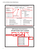
12V Charger connection 12V Battery 40A Fuse Motor Starter relay Key switch Module Blade brake switch Starters Schematic 83
61, 65 and 70 Series Vertical Shaft Engines 84
Ignition System CHAPTER 7: IGNITION SYSTEM Troubleshooting the ignition system The purpose of the ignition system is to provide a spark in the combustion chamber at the proper time to efficiently ignite the fuel/air mixture. The steps in troubleshooting the ignition system are: 1. Examine the spark plug(s) by following the steps described in the spark plug section of this chapter. NOTE: It is convenient to check the compression when the spark plug is removed for examination. 2.
61, 65 and 70 Series Vertical Shaft Engines Troubleshooting the stop switch NOTE: the stop switch could be mounted near the carburetor or if the engine is equipped with an engine brake, the stop switch will be located on the engine brake. The switch is designed to ground out the module. To test the stop switch: 7a. Locate the terminal that connects the stop switch wire to the primary windings of the ignition module. See Figure 7.2. Stop switch 7b.
Ignition System Safety bail in OFF position, Module primary windings are grounded 7e. If further investigation is required, remove the recoil assembly by following the steps described in Chapter 6: Starter. 7f. Visually trace the wire from the stop switch to the connector on the module, and inspect the wire for any damaged insulation or potential contact with ground. 7g.
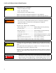
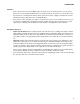
61, 65 and 70 Series Vertical Shaft Engines 9c. Simple spark-testers are readily available and inexpensive. Thexton Part # 404 is available from a variety of retailers, and similar units are available form other manufacturers. See Figure 7.8. Instructions on back of package Figure 7.8 9d. At operating speed, the ignition should produce voltage approaching 12,000. See Figure 7.9. 1 reticle = 4,000 Volts waveform is 3 reticles tall Figure 7.9 9e.
Ignition System 10. Resistance in the primary windings of the ignition module, measured between the spade terminal and the laminations, was observed to be in the 550-650 range. See Figure 7.11. Probe to laminations Probe to stop switch spade terminal Figure 7.11 10a. Resistance in the secondary windings of the ignition module, measured between the spark plug terminal and the laminations, was observed to be in the 8K-9Krange. See Figure 7.12.
61, 65 and 70 Series Vertical Shaft Engines NOTE: Intermittent failure requires tests for voltage and resistance to be made when the engine is cold, and again when it is hot. Typical customer complaint: “It stops after I mow for 10 minutes and I can’t get it to re-start”. • To confirm that the problem is ignition-based, it is necessary to “catch it in the act”. • Resistance normally increases slightly as temperature increases. NOTE: Failure of the magnets in the flywheel is exceedingly rare.
Ignition System About the spark plug • The spark plug is a F6RTC, part #951-10292, gapped to 0.024” - 0.031” (0.6 - 0.8 mm). NOTE: The X65 engine uses a F5RTC, part #951-14437, gapped to 0.024” - 0.031” (0.6 - 0.8 mm). • Wear rate will vary somewhat with severity of use. If the edges of the center electrode are rounded-off, or any other apparent wear / damage occurs, replace the spark plug before operating failure (no start) occurs. Cleaning the spark plug • Cleaning the spark plug is not recommended.
61, 65 and 70 Series Vertical Shaft Engines Ignition module The ignition system is either a capacitive discharge or a inductive discharge magneto, depending on the application, contained in a single module. • The capacitive discharge has a three leg design. • The inductive discharge magneto has a two leg design. • The magneto is energized by the passing of a pair of magnets mounted in the flywheel. • Ignition timing is set by the location of the flywheel in relation to the crankshaft.
Ignition System Installing the module and setting the air gap NOTE: If just setting the air gap, loosen the module mounting screws first then follow the same steps as described below. .012” feeler gauge 1. Rotate the flywheel so that the magnets are away from where the module is mounted. 2. Install the module. Do not tighten the module down. 3. Place a non-ferrous feeler gauge between the module and the flywheel. See Figure 7.16. NOTE: The air gap should be 0.012” - 0.020” (0.3 - 0.5 mm).
61, 65 and 70 Series Vertical Shaft Engines Engine brake and stop switch (if equipped) The stop switch and brake (for lawn mower applications) must be able to stop the blade from rotating within 3.0 seconds after the release of the safety bail, per ANSI B71.1-2003 standard. NOTE: The brake should be replaced when the thickness of the pad is less than .25” (6.35mm) at the thinnest spot. To replace the brake assembly: 1. Disconnect and ground the spark plug wire. 2.
Ignition System Adjusting the brake assembly (if equipped) Screw: pivot point 1. Disconnect and ground the spark plug wire. 2. Remove the recoil assembly and blower housing by following the steps described in Chapter 6: Starter. 3. Slightly loosen the two bolts that holds the brake assembly in place using a 10mm wrench. NOTE: The bolt near the cylinder is a pivot point and the bolt by the dip stick is in a slot. See Figure 7.20. 4.
61, 65 and 70 Series Vertical Shaft Engines Flywheel There are two types of flywheels available for the MTD engine. An aluminum flywheel and a 3-piece cast iron flywheel. See Figure 7.22. Cast iron flywheel NOTE: The procedure for removing the flywheel is the same for both aluminum and cast iron flywheels. To remove the flywheel: 1. Remove the recoil assembly by following the steps described in Chapter 6: Starter. Aluminum flywheel Figure 7.22 Fan shroud 2.
Ignition System NOTE: If equipped with an engine brake, clamp off the brake using a spring clamp. See Figure 7.25. Figure 7.25 4. Remove the flywheel by applying a sharp blow to the crankshaft using a brass drift punch and a hammer while gently prying with a prybar. The flywheel will “pop” loose then lift it off. NOTE: Never strike the crankshaft directly with a hammer. To prevent damage to the crankshaft use a brass drift punch or a piece of wood between the hammer and the crankshaft. See Figure 7.26.
61, 65 and 70 Series Vertical Shaft Engines Starter cup protrusion IMPORTANT: The taper in flywheel and the on the crankshaft must be clean and dry. The flywheel is held in place by the friction fit between the flywheel and the crankshaft, not the key. The key is only to guide the flywheel to the proper position until it is torqued down. 7. Install the flywheel nut to a torque of 47 - 52 ft lbs (64-70 Nm).
Exhaust CHAPTER 8: EXHAUST The exhaust system is a frequently overlooked component of an engine. It is important to make sure the muffler is in good condition and free of debris and/or insects. NOTE: A blocked muffler will result in poor performance. If a muffler is completely blocked the engine may not start. The MTD engine uses one of two different mufflers; a standard muffler covered here or a catalytic converter muffler that will be covered later in this chapter.
61, 65 and 70 Series Vertical Shaft Engines 2. Slide the muffler off of the studs. See Figure 8.3. Figure 8.3 NOTE: The muffler gasket extends well beyond the port, to act as a heat shield and guides cooling air between the muffler and the cylinder. See Figure 8.4. NOTE: The exhaust gasket is made of a graphite material. It will stick to the sealing surfaces when pressure is applied, tearing when pressure is relieved. The gasket can only be used one time. 3.
Exhaust Catalytic converter muffler The CARB (California) compliant engines use a catalytic converter muffler. This muffler also has an air injector to help with the catalytic reaction in the muffler. The Catalytic muffler can be identified by the presence of this air injector. See Figure 8.5. NOTE: The catalytic converter muffler is removed/ replaced by following the same procedures as the conventional muffler.
61, 65 and 70 Series Vertical Shaft Engines To service/replace the air injector: 1. Remove the two screws that secure the air injector using an 8mm wrench. See Figure 8.7. Remove these screws Figure 8.7 2. Remove the two screws that secure the screen cover using a #2 Phillips screw driver. See Figure 8.8. Screen cover NOTE: If the inlet screen is blocked, it may be: 3. • Replaced • Cleaned by mechanical means • Solvent cleaned • Burned clean using a butane or propane torch.
Cylinder head CHAPTER 9: CYLINDER HEAD The Cylinder head of the MTD engine can be removed without removing the engine from the application. To remove the cylinder head: NOTE: If possible, It is recommended that the machine be positioned on the bench so that the cylinder head is vertical for removal. See Figure 9.1. NOTE: This position provides easy access to most service points, yet prevents undue oil spillage. NOTE: Do not store the engine in this position for a long period of time.
61, 65 and 70 Series Vertical Shaft Engines 5. 6. Loosen the jam nuts and fulcrum nuts that secure the rocker arms using a 10mm wrench and a 14mm wrench. See Figure 9.3. Pivot the rocker arms aside, or remove them completely, and remove the push rods. NOTE: Once broken-in, the rocker arm should be kept with its corresponding valve. NOTE: The intake and exhaust push rods are identical and interchangeable.
Cylinder head NOTE: Current production has the dowels on a diagonal. See Figure 9.6. 12. Carefully clean all sealing surfaces of all gasket residue. Do not scratch the sealing surfaces. NOTE: Make a visual inspection of the valves and cylinder bore to confirm the initial diagnosis. 13. Place a new head gasket on the cylinder, allowing the alignment dowels to hold it in place. Alignment dowels NOTE: Early production used siliconized head gasket.
61, 65 and 70 Series Vertical Shaft Engines Valves Valves and valve parts, like springs and keepers, are not available as service parts. The valves and valve seats can be serviced by grinding and lapping or the head can be replaced. Depending on local machine and labor costs, it is probably more economical to replace the cylinder head versus servicing the valves. To service the valves: NOTE: Servicing valves during the warranty period will void the warranty.
Cylinder head 6. Inspect the valve seat. See Figure 9.10. • Valve seats are 45 degrees, with a 15 degree topping cut and a 75 degree narrowing cut. • Seat width should be 0.043” - 0.050” (1.1 - 1.3 mm) with a margin of 0.024” (0.6mm) on the exhaust valve and 0.027” (0.7 mm) on the intake valve. o Seat angle is 45 .043-.050” NOTE: The valve seat can be ground to clean it up as long as the finished seat is within the tolerances listed above. Figure 9.10 7. Inspect the valve stem. See Figure 9.11. 8.
61, 65 and 70 Series Vertical Shaft Engines 108
Crankshaft, piston and connecting rod CHAPTER 10: CRANKSHAFT, PISTON AND CONNECTING ROD There are a a few different paths that can be followed when disassembling an engine. This chapter will cover the removal of components in one order, but it is written so that the technician can jump around to the component being removed. The first step to disassemble the engine is to remove the engine from the application by following the steps described in the service manual for that particular application. 1.
61, 65 and 70 Series Vertical Shaft Engines NOTE: The thrust washer should be removed when the sump is removed. 11. Remove the camshaft. See Figure 10.2. NOTE: Align the timing marks to allow easier removal of the cam shaft and to help protect the compression relief from damage. Cam shaft Compression relief Figure 10.2 NOTE: Early production of the 1P70 series engines had a steel cam shaft. See Figure 10.3. Figure 10.3 12. Remove the valve tappets. See Figure 10.4. Valve tappets Figure 10.
Crankshaft, piston and connecting rod Place a match mark here 13. Remove the connecting rod cap using a 10mm wrench. See Figure 10.5. NOTE: Match mark the connecting rod cap and the connecting rod so that they can be reassembled in the proper orientation. Remove the connecting rod bolts Figure 10.5 Connecting rod NOTE: Rotating the crank shaft after the connecting rod bolts are removed will help to separate the connecting rod from the cap. See Figure 10.6. Cap Figure 10.6 14.
61, 65 and 70 Series Vertical Shaft Engines 16. Remove the crank shaft. See Figure 10.8. Lift up on crank shaft Figure 10.8 Crank shaft inspection 1. Inspect the crank shaft journals for galling, scoring, pitting or any other form of damage. 2. Measure the journals at the bearing contact points using a vernier caliper or a micrometer. See Figure 10.9. 3. Inspect the crankpin for galling, scoring, pitting or any other form of damage. 4.
Crankshaft, piston and connecting rod Piston Inspection Piston ring 1. Clean the piston and remove all carbon from the rings and ring groves. 2. Insert one ring into the cylinder. Push it down about one inch from the top. See Figure 10.11. 3. Measure the end gap with a feeler gauge and compare to the chart at the end of this chapter. See Figure 10.11. 4. Repeat steps 3 and 4 on the other rings. Feeler gauge NOTE: Piston rings are not available as service parts.
61, 65 and 70 Series Vertical Shaft Engines 6. Measure the distance between the ring and the ring land using a feeler gauge and compare the measurement to the chart at the end of this chapter. See Figure 10.14. Feeler gauge Figure 10.14 Connecting rod inspection 1. Inspect the connecting rod for cracks or any signs of damage. 2. Install the rod cap and tighten to a torque of 102 111 in-lbs (11.5-12.5 Nm) 3.
Crankshaft, piston and connecting rod Cylinder inspection Measure the cylinder bore 1. Clean and inspect the cylinder, inside and out. NOTE: If there is any sign of damage, especially cracked cooling fins, short block the engine. NOTE: Take two measurements of the cylinder bore 90 degrees apart at the top, bottom and middle of the cylinder. See Figure 10.16. Figure 10.
61, 65 and 70 Series Vertical Shaft Engines NOTE: On the X65 series of engines, the cylinder is manufactured using a special machining process. This process does not leave a cross hatch that is normally seen in most engines. As the engine breaks in, the cylinder will develop a smooth, dull finish. NOTE: The cylinder may have some scratches. As long as the scratches cannot be felt with a finger nail, they are acceptable. See Figure 10.19. NOTE: Do not de-glaze an X65 series engine cylinder.
Crankshaft, piston and connecting rod Reassembly 1. Troy-Bilt seal driver 2. Clean the cylinder 1a. Remove all gasket material from all mating surfaces. 1b. Clean the cylinder and sump. Oil seals 2a. Install a new oil seal in the cylinder block. NOTE: A piece of 1” schedule 40 PVC pipe can be used as a seal driver. 2b. Install a new seal in the sump. See Figure 10.22. NOTE: Use a Troy-Bilt tiller seal service tool # TWX-4006 to install the sump oil seal. Figure 10.22 3.
61, 65 and 70 Series Vertical Shaft Engines 4d. Tap the piston through the ring compressor into the cylinder using a wooden hammer handle. See Figure 10.25. NOTE: Make sure the crankshaft journal is at BDC (bottom dead center) to prevent damage from the connecting rod. Tap piston with hammer handle Figure 10.25 4e. Pre-lube the connecting rod with clean 10W-30 motor oil or engine assembly lube. Install the connecting rod cap 4f. Install the connecting rod cap.
Crankshaft, piston and connecting rod 6. Install the cam shaft by: 6a. Pre-lube the cam shaft with clean 10W-30 motor oil or engine assembly lube. 6b. Rotate the crank shaft until the timing mark points to the tappets. 6c. Insert the cam shaft while aligning the timing marks. See Figure 10.28. Timing marks Figure 10.28 oil return deflector Thrust washer 7. If removed, install the governor arm by following the steps described in Chapter 4: Fuel systems and Governor. 8.
61, 65 and 70 Series Vertical Shaft Engines 10. Install the sump by: 10a. If removed, install the governor gear and cup by following the steps described in Chapter 4: Fuel system and Governor. 10b. Place a new gasket on the sump, let the alignment dowels hold it in place. Governor cup 10c. Rotate the governor arm so that it is pointing straight up. 10d. Using a seal protector, slide the sump on to the crank shaft. NOTE: The governor arm must slide between the governor cup and the governor arm stop.
Crankshaft, piston and connecting rod Engine specifications chart New Min Inch Metric New Max Inch Metric Service Limit Inch Metric Displacement P61 122.7 cc (7.5^3) P65 139.4 cc(8.5^3) X65 159.3 cc (9.7^3) P70 173.2 cc (10.6^ 3) Bore (new) P61 2.402 61.015 2.403 61.025 2.409 61.182 P65 2.559 65.005 2.560 65.015 2.567 65.193 X65 2.559 65.005 2.560 65.015 2.566 65.183 P70 2.756 70.000 2.756 70.015 2.764 70.196 P61 0.000 0.000 0.000 0.005 0.000 0.005 P65 0.
61, 65 and 70 Series Vertical Shaft Engines New Min Inch Metric New Max Inch Metric Service Limit Inch Metric P65 0.983 24.970 0.984 24.985 0.979 24.864 X65 0.999 25.370 0.999 25.385 0.995 25.262 P70 0.983 24.970 0.984 24.985 0.979 24.864 P61 1.023 25.984 1.023 25.993 1.021 25.943 P65 1.023 25.984 1.023 25.993 1.021 25.943 X65 1.023 25.980 1.023 25.993 1.021 25.943 P70 1.181 29.985 1.181 29.995 1.179 29.937 P61 1.024 26.010 1.024 26.020 1.026 26.
Crankshaft, piston and connecting rod New Min Inch Metric New Max Inch Metric Service Limit Inch Metric Connecting rod to crank pin running clearance P61 0.001 0.017 0.001 0.036 0.002 0.057 P65 0.001 0.017 0.001 0.036 0.002 0.057 X65 0.001 0.017 0.001 0.036 0.002 0.057 P70 0.001 0.020 0.002 0.040 0.002 0.063 P61 0.984 25.000 0.985 25.021 0.994 25.247 P65 0.984 25.000 0.985 25.021 0.994 25.247 X65 1.000 25.400 1.001 25.421 1.010 25.651 P70 0.984 25.
61, 65 and 70 Series Vertical Shaft Engines New Min Inch Metric New Max Inch Metric Service Limit Inch Metric P65 0.551 14.000 0.552 14.018 0.553 14.048 X65 0.551 14.000 0.552 14.018 0.553 14.048 P70 0.551 14.000 0.552 14.018 0.553 14.048 P61 1.085 27.550 1.093 27.750 1.081 27.465 P65 1.085 27.561 1.089 27.661 1.079 27.411 X65 1.085 27.561 1.089 27.661 1.079 27.411 P70 1.088 27.630 1.092 27.730 1.086 27.593 P61 1.083 27.511 1.091 27.711 1.081 27.
Crankshaft, piston and connecting rod New Min Inch Metric New Max Inch Metric Service Limit Inch Metric Intake valve lash P61 0.004 0.100 0.006 0.150 P65 0.004 0.100 0.006 0.150 X65 0.004 0.100 0.006 0.150 P70 0.003 0.080 0.005 0.120 P61 0.006 0.150 0.008 0.200 P65 0.006 0.150 0.008 0.200 X65 0.006 0.150 0.008 0.200 P70 0.005 0.130 0.007 0.170 P61 0.024 0.600 0.031 0.800 P65 0.024 0.600 0.031 0.800 X65 0.024 0.600 0.031 0.800 P70 0.024 0.
61, 65 and 70 Series Vertical Shaft Engines Engine torque values chart Fastener Torque P61 P65 X65 P70 Blower housing studs 89 in lbs (10 Nm) 89 in lbs (10 Nm) 89 in lbs (10 Nm) 89 in lbs (10 Nm) Breather cover 27 - 35 in lbs (3 - 4 Nm) 27 - 35 in lbs (3 - 4 Nm) 27 - 35 in lbs (3 - 4 Nm) 27 - 35 in lbs (3 - 4 Nm) Carburetor drain bolt 53 - 80 in lbs (6 - 9 Nm) 53 - 80 in lbs (6 - 9 Nm) 53 - 80 in lbs (6 - 9 Nm) 53 - 80 in lbs (6 - 9 Nm) Carburetor mounting nuts 80 - 106 in lbs (9 - 12
Failure Analysis CHAPTER 11: FAILURE ANALYSIS A properly maintained engine will provide years of service. Occasionally an engine will fail. An important part of working on engines is being able to recognize the root cause of engine failures. Was it something the customer did? Was it a manufacturing defect? Did the engine just wear out? All of these questions need to be answered. Identifying and eliminating the cause of the failure is the only way to prevent recurring failures.
61, 65 and 70 Series Vertical Shaft Engines 5. 6. When particles enter the combustion chamber, the up and down motion of the piston grinds the particles into the side of the cylinder walls and damages the cylinder wall, piston and piston rings. Cross hatch polished off This can be identified by the scoring along the vertical axis of the piston and cylinder wall or the cross hatch on the cylinder wall being worn off. See Figure 11.2. NOTE: The X65 series does not have a cross hatch to wear off.
Failure Analysis 8. Because the oil suspends the particles, the engine components that are immersed in oil will show definite signs of abrasive ingestion especially around the connecting rod and main bearing journals. See Figure 11.5. NOTE: Abrasives that are trapped in the oil will cause the lower portion of the combustion chamber to wearing more than the upper portion. NOTE: Wear of only one bearing surface on a new engine could be a sign of a manufacturing defect. Figure 11.
61, 65 and 70 Series Vertical Shaft Engines Insufficient lubrication The bearing surfaces in an engine are not smooth. The machining processes used to make the engine parts, leave little peaks and valleys that are only visible under a microscope. These peaks are called asperities. As the engine breaks in, the asperities break off leaving plateaus that become the bearing surface. The valleys become reservoirs for the lubricant.
Failure Analysis Discoloration 3. Metal transfer is the primary indicator that the film of oil between two engine parts has been violated. If the damage is localized, a general failure of the lubrication system is probably not the cause. As an example: a piston skirt shows metal transfer to the cylinder wall. The connecting rod and wristpin show some signs of excessive heat. The main bearings and camshaft are not damaged. This would indicate that the problem was probably related to cylinder temperature.
61, 65 and 70 Series Vertical Shaft Engines Engine Overspeed The MTD engine is designed for a maximum speed of 3300 rpm. When the governor is unable to control the engine rpm, the engine can accelerate past the safe maximum speed. When an engine runs beyond its designed speed, a few things happen: 1. As the piston moves up and down in the cylinder, it builds momentum. The higher the rpm’s the more momentum produced by the pistons. As the momentum builds, the connecting rods will start to stretch.
Failure Analysis Overheated The MTD engines are air cooled engines. Because of this, cleanliness of the engine is very important to the life of the engine. Dirt, grass and sludge all form an insulating layer on the engine. This will trap the heat in the engine and cause it to over heat. Discolored rockers As metal parts heat up enough to change their properties, they will take on a yellowish or blue cast. As oil is heated to the point that it evaporates, black deposits are left behind.
61, 65 and 70 Series Vertical Shaft Engines Mechanical Breakage/ Wear Sometimes an engine fails because a part breaks. There are generally three causes of a broken part, outside of the previously discussed engine failures. They are abuse, wear, and manufacturing defects. Bent blade A very common sign of an abused engine is a bent crank shaft. Crankshafts bend when they, or something bolted to them hits something. A prime example of this is when a mower blade hits a rock. See Figure 11.12.
MTD Products Inc - Product Training and Education Department FORM NUMBER - 769-03354-02 12/2013