Professional Shop Manual 61/65/70/75 Series Horizontal Shaft Engines NOTE: These materials are for use by trained technicians who are experienced in the service and repair of outdoor power equipment of the kind described in this publication, and are not intended for use by untrained or inexperienced individuals. These materials are intended to provide supplemental information to assist the trained technician.
Table of Contents Chapter 1: Introduction Professional Service Manual Intent .................................................................. 1 Safety ................................................................................................................ 1 Fasteners .......................................................................................................... 3 Assembly instructions .......................................................................................
Chapter 4: The Fuel System and Governor Fuel Line ......................................................................................................... 41 Inspect the fuel lines ....................................................................................... 41 Inspecting the fuel........................................................................................... 42 Test fuel for alcohol .........................................................................................
Chapter 7: Ignition System 81 Troubleshooting the ignition system ............................................................... 81 Stop switch ..................................................................................................... 82 Remote (ignition) stop switch ......................................................................... 83 The module .................................................................................................... 85 Module removal .........................
iv
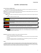
Introduction CHAPTER 1: INTRODUCTION Professional Service Manual Intent This manual is intended to provide service dealers with an introduction to proven diagnostic and repair procedures for MTD 61, 65, 70 and 75 series horizontal shaft engines. Disclaimer: The information contained in this manual is correct at the time of writing. Both the product and the information about the product are subject to change without notice.
61/ 65/70/75 Series Horizontal Shaft Engines • Be prepared in case of emergency: ! CAUTION Keep a fire extinguisher nearby Keep a first aid kit nearby Keep emergency contact numbers handy • Replace any missing or damaged safety labels on shop equipment. • Replace any missing or damaged safety labels on equipment being serviced. • Grooming and attire: Do not wear loose fitting clothing that may become entangled in equipment.
Introduction Fasteners • Most of the fasteners used on the MTD engine are metric. Some are fractional inches. For this reason, wrench sizes are frequently identified in the text, and measurements are given in U.S. and metric scales. • If a fastener has a locking feature that has worn, replace the fastener or apply a small amount of releasable thread locking compound such as Loctite® 242 (blue). • Some fasteners, like cotter pins, are single-use items that are not to be reused.
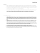
61/ 65/70/75 Series Horizontal Shaft Engines MTD Horizontal Engine Model Designators Starter/Alternators 161- SHA 1=Recoil start 2=Electric start 3=E. start/alt. 20W/20W 4=E. start/alt. 3A DC/5A Major Revision Change Compliance U H C 0 (Zero) L G T Y W United States (50 State) Europe California 49 State 49 State - special U.S.(49) and Europe Australia (S.A.) China U.S.(50) and Europe Bore Dia.
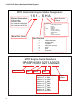
Introduction Model and serial number The model and serial number can be found on a white sticker with a bar code. The sticker is usually located at the base of the engine, under the valve cover. See Figure 1.1. Model number Figure 1.1 NOTE: The serial number will always start with the model number. Maintenance The recommended maintenance intervals listed in this manual are a guideline. They are adjustable for local conditions.
61/ 65/70/75 Series Horizontal Shaft Engines Spark plugs The information in this manual applies to the MTD engine. Some basic principles may apply to engines produced by other manufacturers. As the saying goes “an ounce of prevention is worth a pound of cure”. The same can be said about preventive maintenance on outdoor power equipment. By changing the spark plug and oil at recommended intervals many failures can be avoided.
Introduction Air filter The main function of the air filter is to trap air borne particles before they reach the carburetor that can cause catastrophic internal engine damage. Paper-pleated element Generally air filters come in two different types, a pleated-paper element, or a foam plastic, sometimes a combination of the two will be used like the one on the MTD engine. See Figure 1.3.
61/ 65/70/75 Series Horizontal Shaft Engines Oil type and capacity The recommended oil for MTD engines is an SAE 10W-30 oil for summer engines and SAE 5W-30 for snow engines. Both oils should have a SM API rating or better. The oil capacity is 17.0- 20.3 fl.oz (0.5-0.6 liters). • Check the oil level daily and change the oil more frequently in severe operating conditions such as high ambient temperature, dusty conditions, or high load use in exceptionally thick grass.
Introduction NOTE: There are two types of dip sticks that can be found on MTD engines; a threaded dip stick that was used on older engines and a quarter turn dip stick that is used on engines currently being produced. See Figure 1.4. Threaded 1/4 turn Figure 1.4 To check the oil with a threaded dip stick: 1. Twist and remove the dip stick from the engine. 2. Clean the oil off of the tip of the dipstick. 3. Re-insert the dipstick without threading it in to get the oil level reading. See Figure 1.5.
61/ 65/70/75 Series Horizontal Shaft Engines Changing the oil NOTE: If the engine has been running, allow the engine to cool before doing any maintenance work. NOTE: The oil should be changed after the first 5 hours of operation and every 25 hours there after. Siphon There are three methods of changing the oil. The application the engine is mounted to will determine which method to use: Siphon the oil out through the dip stick tube A. Insert the siphon hose into the dip stick tube. See Figure 1.7. B.
Introduction Fuel system What you should know about fuel. Most of the fuel presently available in North America is oxygenated to some extent. This is commonly done through the addition of ethanol. Most engines offered for sale on outdoor power equipment in the North American markets are designed to tolerate no more than 10% ethanol by volume Ethanol is hygroscopic, meaning it absorbs water. If left exposed to air, it will draw water out of the air.
61/ 65/70/75 Series Horizontal Shaft Engines 5. Install a new filter by following the above steps in reverse order. NOTE: Apply a small amount of a thread sealing compound such as Loctite® 564 and tighten the filter by hand and the an additional 3/4 to 1 full turn. See Figure 1.11. Figure 1.
Introduction Valve lash Valve lash is the clearance between the top of the valve stem and the rocker arm. The valve lash should be checked after the first 25 hours of use and every 100 hours after that. Valve lash can be checked and adjusted using the following steps:. Spark plug Muffler High tension lead 1. If the engine has been run, allow it to cool thoroughly. Position the unit for easy access to the cylinder head. 2.
61/ 65/70/75 Series Horizontal Shaft Engines 61/65/70 series engines 6. Check valve lash between each valve stem and rocker arm using a feeler gauge. 6a. 0.004” feeler gauge Intake valve lash should be 0.004” - 0.006” (0.10 - 0.15 mm). See Figure 1.14. Setting intake valve lash Figure 1.14 14 6b. Exhaust valve lash should be 0.006” - 0.008” (0.15 - 0.20 mm). See Figure 1.15. 6c. Use a 10mm wrench to loosen the jam nut, and a 14mm wrench to adjust the rocker arm fulcrum nut.
Introduction 75 series engines 6. Feeler gauge Check valve lash between each valve stem and rocker arm using a feeler gauge. 6a. Intake valve lash should be 0.004” - 0.006” (0.10 - 0.15 mm). See Figure 1.16. 6b. Exhaust valve lash should be 0.006” - 0.008” (0.15 - 0.20 mm). See Figure 1.17. 6c. Use a 10mm wrench to loosen the jam nut. Adjust the jack screw using a small flat headed screw driver. Figure 1.
61/ 65/70/75 Series Horizontal Shaft Engines Exhaust system The exhaust system is a frequently overlooked component of an engine. It is important to make sure the muffler is in good condition and free of blockage. NOTE: A blocked muffler will result in poor performance. If a muffler is completely blocked, the engine may not start. Cleaning the engine 1. To maintain a proper operating temperature and to keep the equipment looking good, all debris should be removed from the engine. 2.
BASIC TROUBLESHOOTING CHAPTER 2: BASIC TROUBLESHOOTING Definitions Troubleshooting - The act of gathering information by performing tests and direct observations. Diagnosis - Developing and testing theories of what the problem is, based on the information gathered in troubleshooting. Introduction Diagnosing an engine is an art form that is built upon several factors. First and most importantly is a good understanding of how the engine works. The second is skills that have been honed by experience.
61/65/70/75 Series Horizontal Shaft Engines IV. Unusual exhaust tone There are tools that the technician can use in order to define the problem, such as: 1. Interview the customer. 1a. Get a good description of their complaint. 1b. If it is an intermittent problem, verify what conditions aggravate the problem as best as possible. 1c. Get an accurate service history of the equipment. 1d. Find out how the customer uses and stores the equipment. 2. Direct observation: 2a.
BASIC TROUBLESHOOTING Identify factors that could cause the problem This is the second step in the troubleshooting process. 1. Crankshaft will not turn. A. Starter not working. This can be an electrical failure or a mechanical failure. The likely suspects are: I. A dead battery. II. A bad ground III. A failure in the electrical circuit. IV. A failure of the starter itself. B. Engine in a bind (external - attachment jammed).
61/65/70/75 Series Horizontal Shaft Engines I. Run the engine with a spark tester in-line between the spark plug wire and the spark plug or use an oscilloscope and see if the spark goes away at the same time the engine dies. II. Check choke operation. a. Black smoke? b. Wet plug? III. Prime test immediately after engine dies. If it restarts, this may indicate a problem with fuel flow to the carburetor. Check the gas cap, fuel line, fuel filter, and the float in the carburetor. 3b.
BASIC TROUBLESHOOTING V. Makes unusual smoke when running a. Black smoke, usually heavy, usually indicates a rich air fuel mixture • Not enough air: air flow blockage or a partially closed choke. • Too much fuel: carburetor float or float valve stuck or metering / emulsion issues with the carburetor. b. White smoke, usually heavy • Oil in muffler, usually the result of improper tipping. The engine will “fog” for a minute or so, then clear-up on its own. • Massive oil dilution with gasoline.
61/65/70/75 Series Horizontal Shaft Engines chirping noise. • Confirm with a compression test and leak-down test. e. Unusual exhaust tone Splashy or blatty • Splashy idle usually indicates a slight rich condition. • May indicate an exhaust blockage, usually slightly muffled. Backfire • On over-run: unburned fuel igniting past exhaust valve. Mixture not burning completely in combustion chamber. It may be too rich or it may be spark-plug or ignition problem.
BASIC TROUBLESHOOTING Repairing the problem The third step in the troubleshooting process is to repair the problem. This step consists of: A. Form a diagnosis by using all of the information gathered from the troubleshooting that was performed. B. Physically perform the repair. The fourth, and hopefully final, step in the troubleshooting process is the follow through. This step consists of: A. Thoroughly test the repaired equipment: confirming that the initial diagnosis was correct.
61/65/70/75 Series Horizontal Shaft Engines Prime test To perform a prime test: 1. Prime the engine through the carburetor throat using a squirt bottle, filled with clean fresh gasoline. 2. Make sure the throttle is in the run position. 3. Attempt to start the engine. 4. If the engine starts and runs long enough to burn the prime, the problem is effectively isolated to the fuel system. Proceed to Chapter 4: The Fuel System and Governor. 5.
BASIC TROUBLESHOOTING 7. Adjust the tester until the gauge’s needle is pointing to the set position. 8. Connect the tester to the adapter. NOTE: If the engine rotates it was not at top dead center. 9. Check the reading on the gauge.
61/65/70/75 Series Horizontal Shaft Engines Compression test To perform a compression test: NOTE: Compression should be in the range of 55 - 80 PSI (3.8 - 5.5 Bar). • Disconnect the high-tension lead from the spark plug and ground it well away from the spark plug hole. • Remove the spark plug using a 13/16” or 21mm wrench. A flexible coupling or “wobbly” extension may help. • Pull the starter rope several times to purge any fuel or oil from the combustion chamber.
BASIC TROUBLESHOOTING PCV testing The PCV valve is located in the valve cover and allows the crankcase pressure to escape. Leakage and blockage are the two failure modes for a PCV system. Either mode will cause crankcase pressure to build-up, though the effects of a blocked PCV are generally more dramatic. Increased case pressure will result in oil entering the combustion chamber. 1. The PCV chamber is vented to the air filter through a molded rubber hose.
61/65/70/75 Series Horizontal Shaft Engines Troubleshooting flow charts Ignition Troubleshooting Engine runs erratically or shuts off, restarts Engine will not start Check for spark Spark No Spark Replace spark plug Check for the correct spark plug Check flywheel and key for damage or sheared key Set proper air gap on ignition module Test ignition module for intermittent or weak spark Check electric starter and battery if applicable Isolate engine from equipment and repeat test Spark Equipment pr
BASIC TROUBLESHOOTING Engine Operation Problems ENGINE KNOCKS OVERHEATS Associated equipment loose or improperly adjusted Excessive engine loading Check for excessive carbon in combustion chamber Low oil level or wrong viscosity oil Loose flywheel examine key, key way and proper flywheel nut torque Cooling air flow obstructed or clogged cooling fins Ignition timing or incorrect spark plug Carburetor improperly adjusted or improper RPM setting* Loose or worn connecting rod Ignition timing or inc
61/65/70/75 Series Horizontal Shaft Engines Engine Operation Problems EXCESSIVE OIL CONSUMPTION Oil level above full Wrong viscosity oil Excessive engine speed Engine cooling fins dirty causing overheating Breather damaged, dirty or improperly installed SURGES OR RUNS UNEVENLY Fuel cap vent obstructed Dirty carburetor or air filter Carburetor improperly adjusted Governor sticking, binding or improper RPM setting Carburetor linkage, shafts or shutters sticking or binding Intermittent spark, check
BASIC TROUBLESHOOTING Engine Operation Problems ENGINE MISFIRES ENGINE VIBRATES EXCESSIVELY Carburetor improperly adjusted Bent crankshaft Wrong or fouled spark plug Attached equipment out of balance Valves sticking or not seating properly Loose mounting bolts Ignition timing or incorrect spark plug If applicable counter balance not properly aligned Excessive carbon build up Improper Valve Lash Weak valve spring 31
61/65/70/75 Series Horizontal Shaft Engines Engine Operation Problems BREATHER PASSING OIL LACKS POWER Oil level too high Air intake obstructed Excessive RPM or improper governor setting Lack or lubrication or improper lubrication Damaged gaskets, seals or "O" rings Carburetor improperly adjusted Breather damaged, dirty or improperly installed Exhaust Obstructed Piston rings not properly seated or ring end gaps are aligned Improper valve lash Angle of operation too severe 32 Loss of compress
AIR INTAKE SYSTEMS CHAPTER 3: AIR INTAKE SYSTEMS MTD builds horizontal crank engines for snow blowers and chore performers. The differences between snow engines and chore engines are the muffler and the air intake system. Therefore the air intake system for the snow and chore engines will be discussed separately, as will the mufflers in a later chapter.
61/65/70/75 Series Horizontal Shaft Engines 5. 6. Disconnect the wire from the ignition switch and the primer line from the primer button. Remove these screws Remove the two screws that fasten the upper heatbox housing to the lower housing and lift out the upper housing. See Figure 3.3. NOTE: Write down or take a picture of how the prime line and ignition wires are routed through the upper heat box housing. Figure 3.3 7.
AIR INTAKE SYSTEMS Pop primer line out of notch while working the shroud off 9. Work the engine shroud off of the carburetor studs. NOTE: Be careful to pop the primer line out of the notch that secures it while working the engine shroud off. See Figure 3.6. 10. Disconnect the fuel line from the fuel tank. NOTE: The barb on the carburetor fuel inlet nipple is very sharp and will damage the inside of the fuel line if the fuel line is removed.
61/65/70/75 Series Horizontal Shaft Engines Chore engines Air filters Paper-pleated element Generally air filters come in two different types, a pleated-paper element or foam. A combination of the two are used on the MTD engine. See Figure 3.9. • Air filters used on the MTD engine are designed to prevent particles larger than 3-5 micron from passing through into the engine. • The filter should be checked on a regular basis possibly several times in a season.
AIR INTAKE SYSTEMS Air filter base and intake elbow To remove the air filter base: Mounting screws 1. Remove the air filter following the steps described in the previous section. 2. Remove the two screws that hold the air filter base to the intake elbow. See Figure 3.12. 3. Lift the base off of the elbow. NOTE: If the engine is equipped with a charcoal canister, remove it by following the procedures described in Chapter 4: Fuel System and Governor. Intake elbow Figure 3.12 4.
61/65/70/75 Series Horizontal Shaft Engines Carburetor Insulator When working around the fuel system, do not bring any sources of heat, spark, or open flame near the work area. ! WARNING 1. Remove the intake elbow by following the previously described steps. NOTE: Drain the fuel tank before starting work to prevent spillage. Remove the fuel line from the fuel tank NOTE: Dispose of drained fuel in a safe and responsible manner. 2. Remove the carburetor. Figure 3.15 2a.
AIR INTAKE SYSTEMS 3. Unhook the spark plug wire from the clip molded into the insulator plate. See Figure 3.18. Spark plug wire Clip Figure 3.18 NOTE: An insulator block separates the carburetor from the cylinder head. There is a gasket on each side of the insulator. See Figure 3.19. NOTE: The gaskets are different, and there is an orientation to the insulator.
61/65/70/75 Series Horizontal Shaft Engines 40
FUEL SYSTEM AND GOVERNOR CHAPTER 4: THE FUEL SYSTEM AND GOVERNOR The function of the fuel system is to store fuel, mix the fuel with air in the correct ratio and deliver it to the intake port. The fuel system consists of the following components: • Fuel tank • Fuel lines • Fuel filter • Carburetor and insulator block NOTE: When working on the fuel systems, look at the whole system. A problem will rarely be isolated to one component. Fuel Line The fuel line used by MTD is GREENbarTM.
61/65/70/75 Series Horizontal Shaft Engines Inspecting the fuel NOTE: Fuel is the maintenance item most often overlooked by consumers. A lot of fuel systems problems are caused by gas that is out of date or fuel with too much alcohol in it. When inspecting the fuel: • Look for water. • Look for dirt. • Look for discoloration. • Sniff carefully to see if it smells like varnish or kerosene. • Save the fuel to show to customer. • Look for oil in the fuel. • Test the fuel for alcohol content.
FUEL SYSTEM AND GOVERNOR Fuel filter New style NOTE: The fuel filter is located in the fuel tank. It can be removed and cleaned with a can of carb cleaner or replaced Figure 4.4 ! WARNING To avoid personal injury or property damage, use extreme care in handling gasoline. Gasoline is extremely flammable and the vapors are explosive. Serious personal injury can occur when gasoline is spilled on yourself and/or your clothes which can ignite. Wash your skin and change clothes immediately.
61/65/70/75 Series Horizontal Shaft Engines Fuel tank vent The fuel tank vent performs the important task of allowing air into the fuel tank. As fuel is being used by the engine, the fuel level in the tank drops. The dropping fuel level then creates a vacuum in the tank. If the fuel tank could not suck air through the vent, the vacuum would prevent the fuel from getting to the carburetor. NOTE: Fuel tanks with a roll over valve vent: See Figure 4.6.
FUEL SYSTEM AND GOVERNOR The fuel tank To remove the fuel tank: Dip stick tube cover 1. Drain the tank. 2. Disconnect the fuel line from the tank by following the steps described in the fuel filter section of Chapter 1: Introduction. 3. Remove the dip stick 4. Remove the dip stick tube cover by removing the two screws. See Figure 4.8. 5. Remove the two nuts from the fuel tank studs. See Figure 4.9. Figure 4.8 Remove these nuts Figure 4.
61/65/70/75 Series Horizontal Shaft Engines 6. Remove the bolt securing the fuel tank mounting tab to the cylinder block. See Figure 4.11. 7. Install the fuel tank by following the above steps in reverse order. Remove this bolt Figure 4.
FUEL SYSTEM AND GOVERNOR Choke MTD engines are equipped with a choke, a primer or both. If equipped with a manual choke, it must be closed to start the engine. The choke should be opened when the engine starts. This can be a source of starting issues with customers who are not familiar with manual chokes. The choke is operated by either a knob or a lever at the carburetor, depending on the application. If the choke plate fails to close fully, the engine will be difficult or impossible to start when cold.
61/65/70/75 Series Horizontal Shaft Engines Choke linkage The rod connecting the choke knob to the choke plate on the carburetor can be bent slightly to facilitate adjustment. To access it: 1. Remove the choke knob and the engine shroud by following the steps described in Chapter 3: Air Intake Systems. 2. Rotate the choke knob shaft to verify full choke movement. See Figure 4.14. 3. If the choke plate does not open fully or close fully, adjust the choke linkage.
FUEL SYSTEM AND GOVERNOR Primers MTD engines use a dry bulb primer. This means that there is no fuel in the primer bulb. The primer works by pushing air into the float chamber of the carburetor when the primer bulb is depressed. This will force fuel to be sprayed out of the main nozzle into the throat of the carburetor. Primer hose To test the primer: 1. Remove the engine shroud by following the steps described in Chapter 3: Air Intake Systems. 2. Reconnect the primer hose to the carburetor.
61/65/70/75 Series Horizontal Shaft Engines Evaporative (EVAP) emissions system NOTE: Gasoline is made from the graduated distillation of crude oil. It consists of a multitude of individual hydrocarbons and has a boiling range of 86 - 410oF (30-210oC)1. The large quantity of hydrocarbons and the low boiling range makes gasoline an ideal fuel for spark ignited, internal combustion engines. However, the hydrocarbons are not good for the environment.
FUEL SYSTEM AND GOVERNOR Troubleshooting the EVAP system NOTE: Troubleshooting a charcoal canister fuel cap is the same as troubleshooting a non-EVAP system. Symptom Cause Fuel leaking from the carburetor throat or vents A blockage in the charcoal canister or between the canister and the tank. Engine starts, then stalls • Roll over valve stuck closed. • Plugged vent line or charcoal canister. • Raw fuel in the charcoal canister.
61/65/70/75 Series Horizontal Shaft Engines Roll over valve vent To remove/replace the roll over valve: 1. Gently pry the roll over valve out of the fuel tank. See Figure 4.19. 2. Inspect the rubber grommet, replace if damaged. 3. Disconnect the vacuum line. NOTE: if the roll over valve is being removed to remove/replace the fuel tank, the vacuum line can remain attached. 4. With the grommet on the roll over valve, install the roll over valve by pressing it into the opening in the tank. 5.
FUEL SYSTEM AND GOVERNOR Charcoal canister To remove/replace the charcoal canister: Charcoal canister 1. Remove the air filter. 2. Remove the two screws that hold the air filter base to the elbow using a #2 Phillips screw driver. See Figure 4.22. 3. Lift the base off of the elbow enough to gain access to the vacuum lines underneath it. 4. Disconnect the vacuum lines. Screws Figure 4.22 Vacuum lines . Figure 4.23 Hooks 5. Gently spread the two hooks while pulling the canister out of the base.
61/65/70/75 Series Horizontal Shaft Engines Testing a charcoal canister To test for a plugged charcoal canister: 1. Remove the charcoal canister by following the procedures described in the previous section of this chapter. 2. Attach a vacuum pump to the smallest nipple of the canister. 3. Apply vacuum. NOTE: The canister should not be able to build a vacuum. If it does, the canister is bad and needs to be replaced. Figure 4.25 4. Attach the vacuum pump to the middle nipple. 5. Apply vacuum.
FUEL SYSTEM AND GOVERNOR Carburetors If diagnosis indicates a fuel problem, inspect the carburetor. This is important even if problems are identified elsewhere in the fuel system.. IMPORTANT: the fuel must be tested for alcohol content before diagnosing anything else on the engine. NOTE: It is important to perform a compression or leak down test before condemning a carburetor. An engine can have a borderline compression reading and not create enough of a vacuum to draw in a sufficient fuel/air charge.
61/65/70/75 Series Horizontal Shaft Engines 3. Remove the bowl bolt using a 10mm wrench. See Figure 4.28. NOTE: From this point an assessment can be made about the viability of rebuilding the carburetor. • If extensive corrosion is evident, replace the carburetor. • If varnish build-up is too extensive to clean, replace the carburetor. Float bowl Drain bolt Flat fiber gasket Bowl bolt with recess in head for O-ring Gasket seal Figure 4.28 4.
FUEL SYSTEM AND GOVERNOR Main jet Bowl gasket 6. Remove the main jet using a narrow-shank straight blade screwdriver. See Figure 4.31. NOTE: Fuel enters the central column through a port about 1/2” (1cm) from the bottom, to help prevent the ingress of any residue in the bottom of the bowl. NOTE: The orifice in the main jet meters fuel into the central column.
61/65/70/75 Series Horizontal Shaft Engines 8. Carefully pry out the metering plug using a small screwdriver. See Figure 4.34. Figure 4.34 9. Examine the metering plug: See Figure 4.35. NOTE: The transition ports are fixed. They are drilled into the throat of the carburetor, down-stream of the venturi. They lie behind the brass welch plug near the pilot screw. 10. Clean the carburetor body in an ultrasonic cleaner. 11. Rinse it thoroughly. 12. Dry the carburetor body using compressed air. 13.
FUEL SYSTEM AND GOVERNOR Governor Governor action The engine speed is controlled by a balance between the force applied by a spring (pulling the throttle open) and a flyweight mechanism within the engine applying force to the governor arm (pushing the throttle closed). See Figure 4.37. NOTE: While the mechanism is simple and robust, it is important to pay attention when working on parts near the governor. Binding caused by interference with mis-routed lines or cables may make the governor unresponsive.
61/65/70/75 Series Horizontal Shaft Engines Governor shaft To remove or replace the governor shaft: 1. Remove the engine from the equipment that it powers. 2. Remove the governor arm by following the previously described steps. 3. Remove the flywheel by following the steps described in Chapter 7: Ignition Systems. 4. Remove the sump and crankshaft from the engine by following the steps described in Chapter 10: Cam, Crankshaft and Piston. 5. Remove the hairpin clip from the governor shaft.
FUEL SYSTEM AND GOVERNOR Governor cup and the governor gear To remove or replace the governor gear and cup: Governor gear shaft 1. Remove the engine from the unit. 2. Remove the governor arm by following the previously described steps. 3. Remove the flywheel by following the steps described in Chapter 7: Ignition Systems. 4. Remove the sump and crankshaft by following the steps described in Chapter 10: Cam, Crankshaft and Piston. 5. Drive out the governor gear shaft using a 5/32” pin punch.
61/65/70/75 Series Horizontal Shaft Engines NOTE: A second thrust washer goes between the governor gear and the cylinder block. Make sure it is in place when installing the governor gear. See Figure 4.44. 7. Thrust washer Install the governor gear and cup by following the above steps in reverse order. NOTE: Check the governor arm for freedom of movement before test running the engine. 8.
Lubrication CHAPTER 5: LUBRICATION Oil type and quantity The recommended oil for MTD engines is an SAE 10W-30 oil with an SM API rating or better. The oil capacity is 17.0- 20.3 fl.oz (0.5-0.6 liters). -4°F 14°F 32°F 50°F 68°F 86°F 104°F SAE 40 SAE 30 SAE 10W30/SAE 10W40 SAE 5W20 -20°C -10°C 0°C 10°C 20°C 30°C 40°C Oil Chart • If the oil is noticeably thin, or smells of gasoline, carburetor repair may be needed before the engine can be run safely.
61/65/70/75 Series Horizontal Shaft Engines Oil dip stick To check the oil level: NOTE: Be sure to check the engine on a level surface with the engine stopped. 1. Remove the oil filler cap and wipe the dipstick clean. 2. Insert the dipstick into the engine block, but do not screw it in. See Figure 5.1. Dip stick Figure 5.1 3. 4. Pull the dip stick out again and read the oil level. See Figure 5.2. upper limit If the level is low, slowly add oil to the upper limit on the dipstick. Figure 5.
Lubrication Dip stick tube removal To remove/replace the dip stick tube: Remove these screws 1. Remove the dip stick. 2. Remove the two screws securing the dip stick cover in place using a #2 Phillips screw driver. See Figure 5.3. 3. Remove the screw at the bottom of the dip stick tube. See Figure 5.4. 4. Pull the dip stick tube out of the engine block and fuel tank. See Figure 5.5. 5. Inspect the O-rings on the dip stick and the dip stick tube. Replace if damaged. 6.
61/65/70/75 Series Horizontal Shaft Engines Lubrication system MTD uses a splash lube system for it’s horizontal shaft engines. The connecting rod has a dipper on it that “splashes” oil around the inside of the engine. See Figure 5.6. Dipper Figure 5.6 NOTE: The cam and tappets were removed for better visualization of the lubrication system. The splashing action will also atomize or change the oil into a mist. There are two oil passages that run along the engine cylinder.
Lubrication Positive crankcase ventilation valve The PCV valve is located inside the valve cover. The function and test procedures for the PCV valve is covered in Chapter 2: Basic Troubleshooting. Breather hose To remove the valve cover and PCV valve: 1. Disconnect and ground the spark plug wire. 2. Squeeze the spring clamp that secures the breather hose to the valve cover nipple and slide it back. Then remove the breather hose from the valve cover nipple. See Figure 5.8. 3.
61/65/70/75 Series Horizontal Shaft Engines 68
Starters CHAPTER 6: STARTER AND CHARGING SYSTEMS Recoil Starter Removal To remove recoil assembly from the engine: 1. Remove the three nuts that secure the recoil assembly to the engine using a 8mm wrench. See Figure 6.1. 2. Install the starter by following the above step in reverse order. Tighten the screws to a torque of 53 71 in-lbs (6-8 Nm). Remove these screws Figure 6.1 Starter Cup The starter cup is a steel cup that is bolted to the flywheel. Starter cup Inspect slots 1.
61/65/70/75 Series Horizontal Shaft Engines 3. Install a starter cup by placing it on the flywheel, with the dimple on the bottom of the starter cup in the dimple in the flywheel. See Figure 6.3. 4. Install the flywheel nut and tighten it to a torque of 47 - 52 ft-lbs (64 - 70 Nm). Starter cup dimple Flywheel dimple Figure 6.
Starters Starter Rope Rope inserted from the inside out The most common failure mode for most recoil assemblies is a broken rope. NOTE: If the spring was not damaged when the recoil sprung back, It is possible to simply remove the remnants of the old rope and install a new rope. 1. Remove the starter by following the steps described earlier in this chapter. 2. Remove the old starter rope by prying out the starter cord knot and pulling the rope out with it. 3. Cut a piece of #4 recoil rope 7’ (2.
61/65/70/75 Series Horizontal Shaft Engines Starter pulley and recoil spring The recoil spring is nested within the starter pulley and both parts are sold as a single part number. ! CAUTION Eye protection should be worn if the starter pulley is to be removed. The recoil spring is under tension and can release as the pulley is removed. If damage is suspected, the recoil may be disassembled by: 1. Remove the starter by following the steps described earlier in this chapter. 2.
Starters Pulley 5. Carefully lift the spring and pulley out of the recoil housing. See Figure 6.9. Housing NOTE: If the spring is undamaged, but has been removed from the pulley, the spring may be re-wound. Hook the end of the spring into the slot in the outer lip of the recess of the pulley and wind the spring into the recess in a counter-clockwise direction. NOTE: Evaluate the damage, including parts prices and local labor rates.
61/65/70/75 Series Horizontal Shaft Engines Electric starter The electric starter is only available on the snow engine. It is powered by an extension cord that is plugged into household 120 volt AC current. The starter and switch assembly are one piece and are not serviceable. Remove these screws To replace the starter assembly: 1. Disconnect the extension cord. 2. Remove the two screws that secures the switch box to the engine. See Figure 6.10. Figure 6.10 3.
Starters Electric starter switch To remove/replace the electric starter switch assembly: 1. Cut the cable tie that secures the alternator harness to the starters power cord. See Figure 6.13. 2. Remove the two screws that hood the switch box assembly to the engine using a #2 Phillips screwdriver. 3. Remove the two screws that attach the starter’s end cap to the starter using a #2 Phillips screwdriver. See Figure 6.14. 4. Slide the end cap and body off of the starter. Cable tie Figure 6.
61/65/70/75 Series Horizontal Shaft Engines 7. Disconnect the ground wire from the end cap. See Figure 6.16. 8. Remove the O-ring. 9. Lift the harness and grommet out of the end cap. Ground wire Figure 6.16 10. Install a new O-ring on the front cover that is still attached to the engine. See Figure 6.17. NOTE: Applying grease to the front cover will help hold the O-ring in place during assembly. O-ring Figure 6.17 11. Slide the starter body over the rotor until it reaches the brushes. 12.
Starters 14. Install the thrust washer. See Figure 6.19. Thrust washer Figure 6.19 15. Press the harness’s grommet into the end cap. See Figure 6.20. Figure 6.20 Green wire 16. Attach the green wire to the end cap. 17. Install a new O-ring on the end cap. See Figure 6.21. NOTE: Applying grease to the O-ring groove will help hold the O-ring in place during assembly. O-ring Figure 6.
61/65/70/75 Series Horizontal Shaft Engines 18. Attach the white and black wires of the harness to the brush housing. See Figure 6.22. Figure 6.22 19. Set the end cap in place. 12 O’clock NOTE: The holes should be at the 6 & 12 O’clock positions. 20. Install the two starter screws with new insulator washers. 6 O’clock Figure 6.23 21. Attach the switch box to the engine. NOTE: The longer screw goes in the bottom hole.
Starters Charging system Description Some engines are equipped with a charging system. The charging system consists of: Magnets • Alternator stator: copper field windings around an iron core. The stator is attached to the engine block beneath the flywheel. • Four magnets on the inside of the flywheel, refer to figure 6.13, that rotate around a stator that is mounted to the cylinder block. As the crankshaft and flywheel rotate, the moving magnets induce a charge in the stator.
61/65/70/75 Series Horizontal Shaft Engines Stator To remove/replace the stator: 1. Remove and ground the spark plug wire. 2. Remove the flywheel by following the steps described in Chapter 7: Ignition System. 3. Remove the baffle that covers the charger harness using a 10mm wrench. 4. Remove the two screws that secures the stator with a 10mm wrench and lift the stator off of the engine. See Figure 6.28. 5. Install the stator by following the above steps in reverse order. 6.
Ignition System CHAPTER 7: IGNITION SYSTEM Troubleshooting the ignition system The purpose of the ignition system is to provide a spark in the combustion chamber at the proper time to ignite the fuel/air mixture. The steps in troubleshooting the ignition system are: 1. Examine the spark plug(s) by following the steps described in the spark plug section of this chapter. NOTE: It is convenient to check the compression when the spark plug is removed for examination. 2.
61/65/70/75 Series Horizontal Shaft Engines Stop switch NOTE: On snow engines, test the remote (ignition) stop switch first.All MTD horizontal engines that are in use in North America have a stop switch built into the throttle lever assembly. MTD engines used on snow blowers have an additional stop (ignition) switch in the engine shroud. Disconnect switch Test the stop switch (throttle) by: 1. Remove the fuel tank by following the steps described in Chapter 4: The Fuel System And Governor. 2.
Ignition System Remote (ignition) stop switch To test the remote stop switch: Disconnect wires 1. Remove the muffler cover. 2. Disconnect the two wires from the remote switch. See Figure 7.5. 3. Connect a digital multimeter to the two tabs on the back of the remote switch. 4. Set the multimeter to the ohms (Ω) scale. Remote switch Figure 7.5 No Continuity • With the key fully inserted, the multimeter should not show continuity. See Figure 7.6. Key Inserted Figure 7.
61/65/70/75 Series Horizontal Shaft Engines 6. Connect one lead of the multimeter to the blue wire that goes to the remote switch. 7. Connect the other lead of the multimeter to a good ground. Blue wire Continuity 8. Set the multimeter to the ohms (Ω) scale. • Continuity Blue wire If the multimeter shows continuity, Check the black wire from the module for an open or replace the module. See Figure 7.8. Figure 7.
Ignition System The module The coil in this ignition system is an inductive discharge magneto, contained in a single module. • The inductive discharge magneto has a two leg design. • The magneto is energized by the passing of a pair of magnets mounted in the flywheel. • Ignition timing is set by the location of the flywheel in relation to the crankshaft. Proper timing is maintained by a steel key. Normal performance of the coil is to produce at least 10,000 volts at starter-rope pull-through speed.
61/65/70/75 Series Horizontal Shaft Engines Module removal 1. Unplug the spark plug. 2. Remove the Heat box (snow engines) and intake elbow by following the steps described in Chapter 3: Air Intake Systems. 3. Unhook the spark plug wire from the clip in the carburetor insulator. See Figure 7.11. 4. Remove the recoil assembly by following the steps described in Chapter 6: Starter. 5. Remove the blower housing. 6. Disconnect the lead that runs from the module to the stop switch. 7.
Ignition System Flywheel The flywheel holds the magnets that induce a field in the module which in turn produces a spark. But it also controls the timing of the ignition system by controlling when the magnets are introduced to the module. A sheared flywheel key will throw off the ignition timing. They are uncommon on the MTD engine. If one is found, check for a bent crankshaft. To Remove and/or inspect the flywheel and key: Brass punch Figure 7.13 ! CAUTION 5. 1. 1.
61/65/70/75 Series Horizontal Shaft Engines The spark plug • The spark plug is a F6RTC, part #951-10292, gapped to 0.024” - 0.031” (0.6 - 0.8 mm). • Wear rate will vary somewhat with severity of use. If the edges of the center electrode are rounded-off, or any other apparent wear / damage occurs, replace the spark plug before operating failure (no start) occurs. Cleaning the spark plug • Cleaning the spark plug is not recommended. If the plug needs to be cleaned, replace it.
Exhaust CHAPTER 8: EXHAUST The exhaust system is a frequently overlooked component of an engine. It is important to make sure the muffler is in good condition and free of debris and/or insects. NOTE: A blocked muffler will result in poor performance. If a muffler is completely blocked, the engine may not start. Summer engines One of the main differences between the summer and the snow engines is the exhaust system. Because of this they will be addressed separately.
61/65/70/75 Series Horizontal Shaft Engines 2. Remove the spark arrestor retaining screw using a #2 Phillips screwdriver. See Figure 8.1. 3. Pry the spark arrestor out of the muffler. See Figure 8.3. 4. The spark arrestor can be: 5. • Replaced • Cleaned by mechanical means • Solvent cleaned • Burned clean using a butane or propane torch. Install the spark arrestor by following steps 1-3 in reverse order. Figure 8.3 To remove/replace the muffler 1.
Exhaust Snow engines Unlike the summer engines, the snow engines are not equipped with spark arrestors. Muffler shroud To remove/replace the muffler: 1. Remove the muffler shroud by taking off the six screws that hold the muffler cover in place using a 10 mm wrench. See Figure 3.6. 2. Remove the four screws securing the muffler shield using a 10 mm wrench and lift it off of the engine. See Figure 8.7. 3. Remove the two muffler nuts using a 13mm wrench and lift the muffler off of the engine.
61/65/70/75 Series Horizontal Shaft Engines 92
Cylinder head CHAPTER 9: CYLINDER HEAD The Cylinder head of the MTD engine can be removed without removing the engine from the piece of equipment. To remove the cylinder head: Disconnect switch 1. Disconnect and ground the spark plug high tension lead. 2. Remove the spark plug using a 13/16” or 21mm wrench. 3. Rotate the crankshaft until it is at TDC of the compression stroke by following the steps described in the valve lash section of Chapter 1: Introduction.. 4.
61/65/70/75 Series Horizontal Shaft Engines 7. 8. Remove the muffler by following described in Chapter 8: Exhaust. the steps Heat baffle Remove the heat baffle. See Figure 9.3. Remove these screws Figure 9.3 9. Remove the four screws securing the valve cover using a 10mm wrench. See Figure 9.4. Remove valve cover Figure 9.4 10. Remove the rocker arms and push rods: 61/65/70 Series heads: A. Loosen the jam nuts and fulcrum nuts that secure the rocker arms using a 10mm wrench and a 14mm wrench.
Cylinder head 75 Series heads A. Loosen the rocker jam nuts. B. Remove the rocker stud nuts. C. Lift the rockers and the carrier off as an assembly. D. Remove the push rods. NOTE: Once broken-in, the rocker arm should be kept with its corresponding valve. NOTE: The intake and exhaust push rods are identical and interchangeable. It is preferable, but not absolutely necessary to return the same push rods to their original locations on engine with substantial (>100 hours) operating time.
61/65/70/75 Series Horizontal Shaft Engines To install a cylinder head: 8. Place a new head gasket on the cylinder, allowing the alignment dowels to hold it in place. See Figure 9.9. Graphite head gasket NOTE: MTD uses graphite head gaskets that have a bead of silicon on them. They are not reusable. Figure 9.9 9. Position the cylinder head on the engine block. 10. Install the 4 head bolts, and tighten them to a step torque of 16 - 18 ft lb.
Cylinder head Valves Valves and valve parts, like springs and keepers, are not available as service parts. The valves and valve seats can be serviced by grinding and lapping or the head can be replaced. Depending on local machine and labor costs, it is probably more economical to replace the cylinder head versus servicing the valves. To service the valves: NOTE: Servicing valves during the warranty period will void the warranty. Warranty valve repairs are to be accomplished by replacing the cylinder head.
61/65/70/75 Series Horizontal Shaft Engines 3. Lift the springs off of the valve stems. 4. Slide the valves out of the cylinder head. NOTE: Only the intake valve has a valve guide seal. See Figure 9.13. Seal Figure 9.13 5. Inspect the valve seat. See Figure 9.14. • Valve seats are 45 degrees, with a 15 degree topping cut and a 75 degree narrowing cut. • Seat width should be 0.043” - 0.050” (1.1-1.3mm) with a margin of 0.024” (0.6mm) on the exhaust valve and 0.027” (0.7mm) on the intake valve.
Cylinder head 6. Inspect the valve stem. See Figure 9.15. 7. Inspect the valve springs. NOTE: Valve spring free length should be at least 1.22” (28.5mm). Original length is 1.44” (36.6mm). 8. Install the valves in the cylinder head by following steps 2 - 5 in reverse order. 9. Test the valves for leaks by: Inspect for a burnt edge 45o 9a. Place the cylinder head on a couple of wood blocks with the valves facing up. 9b.
61/65/70/75 Series Horizontal Shaft Engines Push rod bushings The MTD engine has bushings for the push rods that need to be replaced from time to time. An indication that the bushings are worn is that the valve lash loosens up. This is because the push rods start moving side to side which opens up the valve lash. NOTE: The 75 series engine does not have push rod bushings. To replace the push rod bushings: 1. Disconnect and ground the spark plug high tension lead. 2.
Cylinder head This side points up, towards the valve cover. NOTE: When installing a push rod bushing plate, make sure the bushings extend away from the cylinder head. See Figure 9.18. 9. Install by following the above steps in reverse order. NOTE: Tighten the rocker studs to a torque of 16 - 18 ft-lbs (22 - 25 Nm). 10. Adjust the valve lash by following the steps described in Chapter 1: Introduction. 11. Test run the mower in a safe area before returning it to service. Check all safety features.
61/65/70/75 Series Horizontal Shaft Engines 102
Crankshaft, piston and connecting rod CHAPTER 10: CRANKSHAFT, PISTON AND CONNECTING ROD There are a a few different paths that can be followed when disassembling an engine. This chapter will cover the removal of components in one order, but it is written so that the technician can jump around, the exact method depends on the type of repair that needs to be made.
61/65/70/75 Series Horizontal Shaft Engines 12. Remove the camshaft. See Figure 10.2. Cam shaft Compression relief Remove the cam shaft Figure 10.2 13. Remove the valve tappets. See Figure 10.3. NOTE: Keep track of which tappet was originally riding on which lobe. Be sure there are reassembled that way. Valve tappets Figure 10.3 14. Remove the connecting rod cap using a 10mm wrench. See Figure 10.4.
Crankshaft, piston and connecting rod Piston ring pliers 15. Push the piston out of the cylinder. 16. Remove the piston rings from the piston using a pair of piston ring pliers. See Figure 10.5. Figure 10.5 17. Remove the crank shaft. See Figure 10.6. Remove the crankshaft Figure 10.
61/65/70/75 Series Horizontal Shaft Engines Crank shaft inspection 1. 2. Bearing contact Inspect the crank shaft journals for galling, scoring, pitting or any other form of damage. area Measure the journals at the bearing contact points using a vernier caliper or a micrometer. See Figure 10.7. NOTE: Micrometers are the preferred and most accurate way to measure the journals. 3. Inspect the crank pin for galling, scoring, pitting or any other form of damage. NOTE: This is mostly a visual check.
Crankshaft, piston and connecting rod Piston Inspection 1. Clean the piston and remove all carbon from the rings and ring groves. 2. Clean the cylinder bore and remove all carbon. 3. Insert one ring into the cylinder. Push it down about one inch from the top. See Figure 10.9. 4. Measure the end gap with a feeler gauge and compare to the chart at the end of this chapter. 5. Repeat steps 3 and 4 on the other rings. Piston ring Feeler gauge NOTE: Piston rings are not available as service parts.
61/65/70/75 Series Horizontal Shaft Engines Connecting rod inspection 1. Inspect the connecting rod for cracks or any signs of damage. 2. Install the rod cap and tighten to a torque of 106 124 in lbs (12 - 14Nm). 3. Measure the inside diameter of the connecting rod and compare the measurements to those listed in the chart at the end of this chapter. See Figure 10.12. Measure at right angles NOTE: Take two measurements 90 degrees apart. This will check the out of roundness of the connecting rod.
Crankshaft, piston and connecting rod Cylinder inspection Measure the cylinder bore 1. Clean and inspect the cylinder, inside and out. NOTE: If there is any sign of damage, especially cracked cooling fins, short block the engine. NOTE: Take two measurements of the cylinder bore 90 degrees apart at the top, bottom and middle of the cylinder. See Figure 10.14. Figure 10.
61/65/70/75 Series Horizontal Shaft Engines Bearings There are two bearings to inspect; a bearing in the crank case cover and one in the cylinder block. To inspect the bearings: 1. Remove the crank case cover and cylinder block oil seals using a seal puller. See Figure 10.16. 2. Inspect the bearing surface for galling, scratches, metal transfer or any other signs of damage. 3. Measure the inside diameter of the bearings and compare to the chart at the end of this chapter. 4.
Crankshaft, piston and connecting rod Reassembly 1. Troy-Bilt seal driver 2. Clean the cylinder 1a. Remove all gasket material from all mating surfaces. 1b. Clean the cylinder and crank case cover. Oil seals 2a. Install a new oil seal in the cylinder block. 2b. Install a new seal in the crank case cover. See Figure 10.17. NOTE: Use a Troy-Bilt tiller seal service tool # TWX-4006 to install the sump oil seal. Figure 10.17 3. Insert the crank shaft into the cylinder block bearing.
61/65/70/75 Series Horizontal Shaft Engines 4a. Compress the piston rings using a piston ring compressor. arrow 4b. Pre-lube the cylinder wall with clean 10W-30 motor oil 4c. Slide the connecting rod and piston into the cylinder. NOTE: The arrow on the piston must point towards the push rod cavity. See Figure 10.20. push rod cavity Figure 10.20 4d. Tap the piston through the ring compressor into the cylinder using a wooden hammer handle. See Figure 10.21.
Crankshaft, piston and connecting rod 5. Install the valve tappets. 6. Install the cam shaft by: Timing marks 6a. Pre-lube the cam shaft with clean 10W-30 motor oil 6b. Rotate the crank shaft until the timing mark points to the tappets. 6c. Insert the cam shaft while aligning the timing marks. See Figure 10.23. Figure 10.23 7. If removed, install the governor arm by following the steps described in Chapter 4: Fuel systems and Governor. 8.
61/65/70/75 Series Horizontal Shaft Engines Engine specifications chart 61 65 minimum SAE Displacement Bore Stroke maximum mm SAE 7.5 cu in 2.402 1.654 mm 123 cc 61.005 2.402 61.015 42.000 1.654 42.000 minimum SAE maximum mm SAE 10.9 cu in 2.559 2.126 65.005 mm 179 cc 2.560 54.000 2.126 65.015 54.000 Compression Ratio 8.7:1 8.7:1 Cranking Pressure 40 - 70 psi (2.8 - 4.8 bar) 40 - 70 psi (2.8 - 4.8 bar) Module air gap 0.016 0.400 0.024 0.600 0.016 0.400 0.024 0.
Crankshaft, piston and connecting rod 61 minimum SAE mm 65 maximum SAE mm minimum SAE mm maximum SAE mm Cam shaft bearing ID (sump) 0.559 14.200 0.560 14.218 0.559 14.200 0.560 14.218 Intake lobe rise 0.213 5.400 0.228 5.800 0.213 5.400 0.228 5.800 Intake lobe base circle diameter 0.433 11.000 0.433 11.000 0.433 11.000 0.433 11.000 Exhaust lobe rise 0.217 5.500 0.232 5.900 0.217 5.500 0.232 5.900 Exhaust lobe base circle diameter 0.433 11.000 0.433 11.000 0.
61/65/70/75 Series Horizontal Shaft Engines 70 75 minimum SAE Displacement Bore Stroke maximum mm SAE 12.7 cu in 2.756 2.126 70.000 mm 208cc 2.756 54.000 2.126 70.010 54.000 minimum SAE maximum mm SAE 14.8cu in 2.953 2.165 75.000 mm 243 cc 2.953 55.000 2.165 75.010 55.000 Compression Ratio 8.7:1 8.7:1 Cranking Pressure 40 - 70 psi (2.8 - 4.8 bar) 40 - 70 psi (2.8 - 4.8 bar) Module air gap 0.016 0.400 0.024 0.600 0.016 0.400 0.024 0.600 Spark plug gap 0.024 0.600 0.
Crankshaft, piston and connecting rod 70 minimum SAE mm 75 maximum SAE mm minimum SAE mm maximum SAE mm Cam shaft bearing ID (sump) 0.559 14.200 0.560 14.218 0.559 14.200 0.560 14.218 Intake lobe rise 0.213 5.400 0.228 5.800 0.237 6.020 0.239 6.060 Intake lobe base circle diameter 0.433 11.000 0.433 11.000 0.433 11.000 0.433 11.000 Exhaust lobe rise 0.217 5.500 0.232 5.900 0.220 5.900 0.235 5.980 Exhaust lobe base circle diameter 0.433 11.000 0.433 11.000 0.
61/65/70/75 Series Horizontal Shaft Engines Engine torque values chart Fastener Torque 61 65 70 75 Blower housing 80 - 106 in lbs (9-12 Nm) 80 - 106 in lbs (9-12 Nm) 80 - 106 in lbs (9-12 Nm) 80 - 106 in lbs (9-12 Nm) Carburetor drain bolt 80 - 106 in lbs (9-12 Nm) 80 - 106 in lbs (9-12 Nm) 80 - 106 in lbs (9-12 Nm) 80 - 106 in lbs (9-12 Nm) Carburetor mounting nuts 80 - 106 in lbs (9-12 Nm) 80 - 106 in lbs (9-12 Nm) 80 - 106 in lbs (9-12 Nm) 80 - 106 in lbs (9-12 Nm) Connecting rod cap
Failure Analysis CHAPTER 11: FAILURE ANALYSIS A properly maintained engine will provide years of service. Occasionally an engine will fail. An important part of working on engines is finding out why they failed. Was it something the customer did? Was it a manufacturing defect? Did the engine just wear out? All of these questions need to be answered when a failed engine is found.
61/65/70/75 Series Horizontal Shaft Engines 5. 6. When particles enter the combustion chamber, the up and down motion of the piston grinds the particles into the side of the cylinder walls and damages the cylinder wall, piston and piston rings Cross hatch polished off This can be identified by the scoring along the vertical axis of the piston and cylinder wall or the cross hatch on the cylinder wall being worn off.
Failure Analysis 8. Because the oil suspends the abrasive particles, the engine components that are immersed in oil will show definite signs of abrasive ingestion especially around the connecting rod and main bearing journals. See Figure 11.5. NOTE: Abrasives that are trapped in the oil will cause the lower portion of the combustion chamber to wearing more than the upper portion. NOTE: Wear of only one bearing surface on a new engine could be a sign of a manufacturing defect. Figure 11.
61/65/70/75 Series Horizontal Shaft Engines Insufficient lubrication The bearing surfaces in an engine are not smooth. As a result of the machining processes to make the engine parts, there are little peaks and valleys that are only visible on a microscopic scale. These peaks are called asperities. As the engine breaks in, the asperities break off leaving plateaus that become the bearing surface. The valleys become reservoirs for the lubricant.
Failure Analysis Engine Overspeed The MTD engine is designed for a maximum speed of 3600 rpm. When the governor is unable to control the engine rpm, the engine can accelerate past the safe maximum speed. When an engine runs beyond its designed speed, a few things happen: 1. As the piston moves up and down in the cylinder, it builds momentum. The higher the rpm’s the more momentum produced by the pistons. As the momentum builds, the connecting rods will start to stretch.
61/65/70/75 Series Horizontal Shaft Engines Overheated The MTD engines are air cooled engines. Because of this, cleanliness of the engine is very important to the life of the engine. Dirt, grass and sludge all form an insulating layer on the engine. This will trap the heat in the engine and cause it to over heat. As metal parts heat up enough to change their properties, they will take on a yellowish or blue cast.
Failure Analysis Mechanical Breakage/ Wear Bent blade Sometimes an engine fails because a part breaks. There are generally three causes of a broken part, outside of the previously discussed engine failures. They are abuse, wear, and manufacturing defects. A very common way to abuse an engine is a bent crank shaft. Crank shafts bend when they, or something bolted to them hits something. A prime example of this is when a mower blade hits a rock. See Figure 11.11. Figure 11.
61/65/70/75 Series Horizontal Shaft Engines 126
MTD Products Inc - Product Training and Education Department FORM NUMBER - 769-04015-01 07/2013