Service Manual Commercial MMZ Rider NOTE: These materials are for use by trained technicians who are experienced in the service and repair of outdoor power equipment of the kind described in this publication, and are not intended for use by untrained or inexperienced individuals. These materials are intended to provide supplemental information to assist the trained technician. Untrained or inexperienced individuals should seek the assistance of an experienced and trained professional.
SECTION 1 Cub Cadet Commercial M60 Tank - 2002 and prior years PTO Belt Removal ......................................................................................................1 Cutting Deck Removal ................................................................................................3 Cutting Deck Drive Belt Removal ...............................................................................5 Spindle Removal and Disassembly ................................................................
2
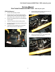
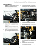
Cub Cadet Commercial M60 Tank - 2002 and prior years Service Manual Cub Cadet Commercial M60 Tank - 2002 and prior years PTO Belt Removal 7. 1. Pivot the seat assembly forward. 2. Remove the lock nut and hex bolt securing the negative battery cable to the negative battery terminal using a 7/16” socket and a 7/16” wrench. 3. Remove the sparkplug wires from the sparkplugs on the engine. 4. Lower the cutting deck to the lowest position. 5.
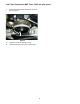
Cub Cadet Commercial M60 Tank - 2002 and prior years 9. Remove the PTO belt from the electric clutch pulley. See Figure 4. PTO Belt Electric Clutch Pulley Figure 4 10. Inspect the V-belt for damage or wear. 11. Install the PTO belt in the reverse order above.
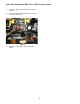
Cub Cadet Commercial M60 Tank - 2002 and prior years Cutting Deck Removal 4. NOTE: Prior to performing this section, the PTO Belt Removal section must be performed. 1. Pull the front mounting rod to the right several inches until the left frame strut and lift brace are free. See Figure 3. Make certain the cutting deck is at the lowest position. See Figure 1.
Cub Cadet Commercial M60 Tank - 2002 and prior years 9. Install the clevis pin and hairpin below the lift handle. 10. Slide the cutting deck assembly out from below the unit. See Figure 5. Cutting Deck Figure 5 11. Install the cutting deck in the reverse order above.
Cub Cadet Commercial M60 Tank - 2002 and prior years Cutting Deck Drive Belt Removal 3. NOTE: Prior to performing this section, the PTO Belt Removal and Cutting Deck Removal sections must be performed. Release the spring tension being applied to the deck drive belt by installing a 1/2" ratchet in the square hole of the idler arm assembly and pulling outward. See Figure 3. 1/2” Ratchet in Square Hole Cutting Deck Idler Arm Assembly Spring Tension Pull Figure 3 4. Figure 1 1.
Cub Cadet Commercial M60 Tank - 2002 and prior years Spindle Removal and Disassembly 5. NOTE: Prior to performing this section, the Cutting Deck Drive Belt Removal section must be performed. 1. Remove the hex flange lock nut securing the blade assembly together using a 1-1/8” socket and a 1-1/8” wrench. 2. Remove the blade and spacer from the large hex cap screw. 3. Remove the large hex cap screw and washer. See Figure 1. Press all of the spindle components apart and inspect for wear or damage.
Cub Cadet Commercial M60 Tank - 2002 and prior years Hydrostatic Drive Belt Removal 1. Pivot the seat assembly forward. 2. Remove the lock nut and hex bolt securing the negative battery cable to the negative battery terminal using a 7/16” socket and a 7/16” wrench. 3. Remove the sparkplug wires from the sparkplugs on the engine. 4. Remove the hex insert lock nuts and flat washers from the input shafts of the right and left hydrostatic pump assemblies using a 3/4" socket. See Figure 1. 5.
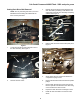
Cub Cadet Commercial M60 Tank - 2002 and prior years 8. 12. Disconnect the PTO clutch connector from the wiring harness connector using a small flat-blade screw driver. See Figure 4. Remove the drive belt from the engine drive pulley. See Figure 6. Engine Drive Pulley Wiring Harness PTO Clutch Connector Figure 6 Figure 4 9. Roll the drive belt up and off of the right transmission pulley. See Figure 5. Drive Belt Transmission Pulley Figure 5 10.
Cub Cadet Commercial M60 Tank - 2002 and prior years Electric PTO Clutch Removal 3. NOTE: Prior to performing this section, the Hydrostatic Drive Belt Removal section must be performed. 1. Loosen the front engine mounting bolts and hex flange lock nuts securing the engine to the frame using a 1/2" socket and a 1/2" wrench. See Figure 3. Remove the hex lock nut securing the negative cable to the right front engine mounting bolt using a 1/2" wrench. See Figure 1.
Cub Cadet Commercial M60 Tank - 2002 and prior years 5. Lift the rear of the engine slightly and remove the electric PTO clutch from the engine crankshaft. See Figure 5. Electric PTO Clutch Figure 5 6. Inspect and test the electric PTO clutch. 7. Install the electric PTO clutch in the reverse order above.
Cub Cadet Commercial M60 Tank - 2002 and prior years Hydrostatic Drive Assembly Removal 6. NOTE: The following section was performed with a lift. Make certain the front castor wheels are rotated rearward for maximum stability. 1. Pivot the seat assembly forward. 2. Remove the lock nut and hex bolt securing the negative battery cable to the negative battery terminal using a 7/16” socket and a 7/16” wrench. 3. Remove the sparkplug wires from the sparkplugs on the engine. 4.
Cub Cadet Commercial M60 Tank - 2002 and prior years 11. Support the bottom of the skid plate assembly from below. 12. Make certain the parking brake is released. See Figure 4. 15. Remove both hairpins and clevis pins securing the brake rod yokes to the brake actuation arms. See Figure 6. Clevis Pin Hairpin Brake Rod Yoke Parking Brake Brake Actuation Arm Figure 6 16. Figure 4 13. NOTE: The brake rod yokes will be pulled forward and out of the way.
Cub Cadet Commercial M60 Tank - 2002 and prior years 18. Remove the hairpin and clevis pin from below the deck lift lever. 19. Push the deck lift lever down as far as it will go and place the clevis pin and hairpin above it. See Figure 8. 21. Remove both of the hex bolts, flat washers and lock nuts securing the right and left hydrostatic pumps to the frame using a 9/16” socket and a 9/16” wrench. See Figure 10.
Cub Cadet Commercial M60 Tank - 2002 and prior years 26. Make certain the hydrostatic fluid drain containers are below the skid plate assembly. 27. Remove all four of the hydraulic line connectors from both hydrostatic pumps using a 3/4" wrench and a 7/8” wrench. 28. Slowly lower the skid plate assembly and remove it from the unit. See Figure 12. Skid Plate Assembly Figure 12 29. Install the hydrostatic drive assembly in the reverse order above.
Cub Cadet Commercial M60 Tank - 2002 and prior years Hydrostatic Pump / Transmission Removal 3. NOTE: The following section has been written for training and includes multiple steps for both the left and right hydrostatic pump / transmission assemblies. Prior to performing this section, the Hydrostatic Drive Assembly Removal section must be performed. Remove both hex bolts and flange lock nuts securing the short connecting rods to the neutral return plates using a 1/2" socket and a 9/16” wrench.
Cub Cadet Commercial M60 Tank - 2002 and prior years 6. Remove all four hex cap screws and flange lock nuts that secure the hydrostatic pump assemblies to the center pump support brackets using a 1/2" socket and a 1/2" wrench. See Figure 5. NOTE: The thick flat washers are used to make up the difference between the hydrostatic pump assembly housings and the skid plate assembly, at the upper rear mounting hole (closest to the dump valve lockout holes). See Figure 7.
Cub Cadet Commercial M60 Tank - 2002 and prior years NOTE: When assembling the transmissions to the skid plate assembly, tighten and then torque the bolts in numerical succession. (outside to inside) See Figure 9. 9 10 11 12 14/15 16/17 2 1 5 6 13 7 8 4 3 Figure 9 Bolt Torque Specifications: Part# Bolt # Size Description Torque 00002528 1-4 3/8-16 x 2.00 Gr 5 Mounts transmission motor to skid plate 33 ft. lbs. 00013198 5-8 5/16-18 x 2.
Cub Cadet Commercial M60 Tank - 2002 and prior years Left Transmission Disassembly and Inspection 3. Remove all four hex flange lock nuts securing the hydrostatic pump assembly to the transmission assembly using a 1/2" socket and a 1/2" wrench. See Figure 3. Transmission Hydrostatic Pump Hex Flange Lock Nuts Figure 1 1. Remove the hex insert lock nut and flat washer securing the hydrostatic fan and pulley to the hydrostatic input shaft using a 3/4" socket. See Figure 2.
Cub Cadet Commercial M60 Tank - 2002 and prior years 6. Set the hydrostatic pump assembly aside. 7. Record the orientation of both hydraulic elbow fittings on the transmission assembly. 8. Remove both hydraulic fittings from the transmission assembly using an 11/16” wrench. See Figure 5. 11. Drive both centering roll pins into the inner case halve using a punch. See Figure 7. Inner Case Half Centering Roll Pins Perimeter Hex Flange Lock nuts and Hex Screws Figure 7 12.
Cub Cadet Commercial M60 Tank - 2002 and prior years 15. Remove the inner housing assembly. 16. Inspect the needle bearing in the inner housing. 19. NOTE: Remove and press in a new bearing if needed. 17. Remove the brake assembly and inspect all of the components. See Figure 11. Brake Retaining Dowel Pins Remove all of the shim washers from the top of the reduction gear. See Figure 9.
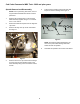
Cub Cadet Commercial M60 Tank - 2002 and prior years 24. Remove the center snap ring securing the axle assembly in position using snap ring pliers. See Figure 13. Center Snap Ring 28. Inspect the outer oil seal and replace it if damaged or worn. See Figure 15. Oil Seal Internal Snap Ring Ball Bearing Axle Assembly Figure 15 Figure 13 25. Press the axle assembly out of the outer ball bearing. See Figure 14. Ball Bearing Axle Assembly Snap Rings Figure 14 26.
Cub Cadet Commercial M60 Tank - 2002 and prior years Left Transmission Shimming and Assembly 6. Secure the axle assembly in position with the center snap ring using snap ring pliers. 1. Make certain both transmission mating faces are clean. 7. 2. If the outer oil seal was removed, press a new one into the outer axle housing until it bottoms out. See Figure 1. Install the output carrier assembly, all three 13T spur gears and the 46T ring gear onto the axle assembly. See Figure 3.
Cub Cadet Commercial M60 Tank - 2002 and prior years 9. Install the reduction gear onto the axle assembly. See Figure 5. Axle Assembly Reduction Gear Figure 5 10. Make certain all of the gears turn smoothly without binding. See Figure 6.
Cub Cadet Commercial M60 Tank - 2002 and prior years Shimming Procedures NOTE: This section requires a measuring device that can measure depth in thousands of an inch. A dial caliper was used to perform this section. Inner Housing 11. Locate a flat section of bar-stock and measure its depth. This is bar-stock (1). See Figure 7. 14. Measure the distance from the top of bar-stock (1) to the top of the center needle bearing boss. 15. Record the measurement._____ This is measurement (B). 16.
Cub Cadet Commercial M60 Tank - 2002 and prior years 22. Measure the total distance of bar-stocks (1) and (2). See Figure 10. (D) Bar Stock 1 (E) Bar Stock 2 Figure 12 25. Figure 10 23. Record the measurement._____ This is measurement (E). 24. Subtract measurement (E) from measurement (D). See Figure 11 and 12. Record this measurement._____ This is measurement (F). NOTE: Measurement (F) is the distance from the mating surface of the outer axle housing to the first shoulder of the axle shaft.
Cub Cadet Commercial M60 Tank - 2002 and prior years 28. 30. Shim the first shoulder of the axle assembly to achieve a 5 to 20 thousands measurement of (Z). See Figure 13. Place a bead of sealant around the outer perimeter of the mating surface. NOTE: Use Loctite 5999 or equivalent. NOTE: Z = 5 to 20 thousands. Shim 31. Set the inner housing on top of the outer axle housing and align the centering roll pins by tapping them into place using a punch and a small hammer. 32.
Cub Cadet Commercial M60 Tank - 2002 and prior years 35. Install both hydraulic elbow fittings to the correct position using an 11/16” wrench. See Figure 16. 40. Place the hydrostatic pulley and fan onto the input shaft. 41. Secure the hydrostatic pulley and fan to the input shaft with a flat washer and hex insert lock nut using a 3/4" socket. See Figure 18.
Cub Cadet Commercial M60 Tank - 2002 and prior years 7 1 3 16 4 7 18 5 11 8 5 10 24 14 13 2 22 15 12 19 9 23 17 21 20 5 5 6 REF. NO. 1. 2. 3. 4. 5. 6. 7. 8. 9. 10. 11. 12. PART NO. 618-3110A 611-3012 710-0852 618-3106 618-3107 618-3109 710-1342 711-1048 712-3027 715-0156 715-0219 715-3045 716-3015 716-3018 18 REF. NO. 13. 14. 15. 16. 17. 18. 19. 20.
Cub Cadet Commercial M60 Tank - 2002 and prior years Neutral Control Adjustment Preparation 4. 1. Check the hydraulic fluid level and raise the rear of the unit off the ground. 2. Remove all four lug nuts securing the right rear wheel assembly to the right axle hub using a 3/4" socket and extension. 3. Remove the right rear wheel assembly.
Cub Cadet Commercial M60 Tank - 2002 and prior years 6. Creep Adjustment Rotate the connecting rods clockwise or counterclockwise until the corresponding lap bars are directly over the neutral slots, and the lap bars pivot out and back freely. See Figure 4. NOTE: If the unit creeps in either direction after the lap bars have been adjusted, and the 1/4" by 28” alignment dowel rod is in place, perform the following steps: 1. Make certain that the rear of the unit is off the ground. 2.
Cub Cadet Commercial M60 Tank - 2002 and prior years 5. 7. Make certain both hydrostatic pump release rods are in the operate position. See Figure 2. With the rear of the unit off the ground, bring the lap bars to the operate position. See Figure 4. Pump Release Rod Figure 2 6. Figure 4 8. Start the unit and release the parking brake. See Figure 3. Identify the rear axle that is creeping. NOTE: The hydraulic fluid must be brought to operating temperature (130 degrees F.) to correctly test for creep.
Cub Cadet Commercial M60 Tank - 2002 and prior years 11. Loosen both hex jam nuts securing the hydrostatic connecting rod in position using a 1/2" wrench and channel locks. 12. Start the unit. 13. Rotate the connecting rod clockwise or counterclockwise until all rear wheel motion has been eliminated. 17. Remove the 1/4" by 28” alignment dowel rod. See Figure 7. CAUTION: The unit will be running during this procedure. 14. Shut the unit off. 15.
Cub Cadet Commercial M60 Tank - 2002 and prior years Parking Brake Adjustment 3. NOTE: Perform the left parking brake adjustment first. 1. Make certain the parking brake lever is fully disengaged. See Figure 1. Place the 1/4" bar-stock between the parking brake lever and the top of the skid plate assembly (at the pump release rod lockout bracket). See Figure 3. 1/4” piece of bar stock Parking Brake Lever Parking Brake Lever (Disengaged) Skid Plate Assembly Figure 3 4. Figure 1 2.
Cub Cadet Commercial M60 Tank - 2002 and prior years 5. 10. Apply light pressure rearward to the brake connecting rod, while turning the front nylon lock nut clockwise or counter-clockwise until the parking brake lever lightly contacts the top of the 1/4" bar-stock using a 9/16” wrench. See Figure 3 on the previous page. Engage the parking brake and inspect for binding. See Figure 7.
Cub Cadet Commercial M60 Tank - 2002 and prior years Mower Deck Leveling Preliminary Setup Side to Side Adjustment 1. Place the unit on level ground and remove the ignition key. 1. 2. Remove both spark plug wires from the engine. 3. Make certain the air pressure in all four tires is set at 10 PSI. Place the clevis pin and hairpin in the three inch setting for the height of cut. See Figure 2.
Cub Cadet Commercial M60 Tank - 2002 and prior years 3. Loosen both of the lower hex jam nuts securing the deck mounting eye bolts to the left deck lift links using two 15/16” wrenches. See Figure 4. Jam Nuts 8. If the right and left measurements are not equal, perform the following steps: 9. Mark the top of each upper hex nut for a reference point. See Figure 6. Mark hex nut with reference point Figure 4 4.
Cub Cadet Commercial M60 Tank - 2002 and prior years Front to Back Adjustment 4. NOTE: For optimum cutting performance, it is important that the cutting deck is level side to side and pitched forward 1/8” to 1/4". 1. Measure the distance from the rear of the cutting blade to the ground and record it._____ NOTE: The front blade measurement should be 1/8” to 1/4" lower than the back blade measurement.
Cub Cadet Commercial M60 Tank - 2002 and prior years Notes: 38
M48 Tank m 1. SECTION 2 - M48/M72 Tank - 2003/04 Update ABOUT THIS SECTION: 3.3. The M48 is part of the Cub Cadet Commercial Tank Series. The 2004 model year M48 is very similar to The 2001 model year Tank. Earlier versions of this machine have been covered in the “2001 Cub Cadet Commercial Technical Handbook”: Form #77010528. 2.
M48 Tank 3.5. 3.7. For complete brake adjustment procedures, refer to the “Brake Adjustment” section of this manual. For the purpose of tracking, insure that the brake linkage bellcranks and rods are well lubricated, not damaged, and work as intended. See Figure 3.5. If in doubt about the source of brake drag, disconnect the brake link rod from the actuator arm on the brake assembly. The actuator arm should return to center, releasing the brakes. See Figure 3.7.
M48 Tank 3.12. If adjustment is necessary, remove the cutting deck. 3.14. Loosen the jam nuts at each end of the hydro control link rods, and rotate the rods to lengthen or shorten them. See Figure 3.14. 3.13. Inspect the return to neutral cylinders, rods, and bellcranks of the hydro control linkages. • The bellcranks should pivot easily without too much play. • The rods should not be bent, and the rod ends should not be loose.
M48 Tank 3.18. If one side does not drive as effectively as the other, test the output of the hydro pump to determine if the problem lies in the pump or the hydro motor. By the process of elimination, if performance is lacking, brake drag is eliminated, adjustment is correct, and the pump is O.K., then the problem is the motor. Pressure and flow tests will be used to determine if the pump is the the source of the problem. 4. 4.4.
M48 Tank 4.15. Remove the stop bolt that sets the end of the travel of the lap bar that controls the hydro pump to be tested. See Figure 4.15. NOTE: The test can be performed at either line between the pump and the motor. The top line on the motor is the in line from the pump when driving forward. The linkage has more travel in forward than it does in reverse, so the test is most easily done on the top line of the pump, driving the pump in the forward direction forward. JAM NUT 4.11.
M48 Tank 4.27. Interpretation: flow droop greater than 1.5 GPM indicates a pump that is not performing as well as it should. 4.23. When the fluid is between 160-210 deg. f. (71-90 deg. c.) apply full forward drive pressure to the lap bar with the engine running at full speed (3600 RPM) while an assistant closes the valve to the point where pressure reaches 300 PSI (21 Bar.). See Figure 4.23. 10 GPM NOTE: A blocked filter may account for some loss of performance. 4.28.
M48 Tank 5.6. Remove the nut, washer, and cooling fan from the hydro pump to be replaced, using a 9/16” wrench. See Figure 5.6. FAN 5.10. Use a small two-jaw puller to remove the pulley from the tapered and keyed input shaft of the hydro pump. See Figure 5.10. NUT PULLER WASHER PULLEY Figure 5.10 Figure 5.6 5.7. Use a 3/8” breaker bar to move the belt tensioner pulley arm, slipping the belt off of the pulley. See Figure 5.7. 5.11.
M48 Tank 5.20. Disconnect the two lines that connect the hydro motor to the back of the hydro pump using a pair of 7/8” wrenches. Plug the lines. See Figure 5.20. 5.14. Open the relief valve on the hydro pump that is to be tested. This will relieve any residual hydraulic pressure. See Figure 5.14. RETURN LINE FEED LINE CLOSE OPEN HYDRO PUMP ELBOW PRESSURE LINES BETWEEN PUMP AND MOTOR HYDRO MOTOR RELIEF VALVE ADAPTORS Figure 5.14 Figure 5.20 5.15.
M48 Tank 5.24. Remove the handle from the relief valve using a 7/16” wrench and a 3/16” allen wrench. 5.29. Position the pulley over the opening in the hydro pump support plate that the pump input shaft will pass through. 5.25. Remove the nuts from the carriage bolts that hold the hydro pump to the hydro pump mounting plate. See Figure 5.25. MOUNTING NUT 5.30.
M48 Tank 5.39. Install the wheels, lower the TANK to the ground, and test run it in a safe area. Make any necessary adjustments before installing the cutting deck. 6. REPLACING THE HYDRO MOTOR 6.1. If the cutting deck is currently on the unit, remove it. 6.2. Safely lift and support the rear of the tank. 6.3. Remove the rear wheels using a 3/4” socket. 6.4. Tilt the seat up, and disconnect the negative battery cable. 6.5.
M48 Tank 6.9. If the brake assembly is to be transferred to the new hydro motor: remove the cotter pin from the castle nut that holds the hub to the axle. 6.13. Disconnect the high pressure lines from the the hydro motor one at a time using a 7/8” wrench. A 1” wrench may be required to hold the fittings on the hydro motor. Plug the lines. See Figure 6.13. 6.10. Loosen, but do not remove the castle nut from the axle using a 11/2” socket.
M48 Tank 6.19. Safely fixture the hydro motor and brake assembly in a minimum 20 Ton press so that the ram presses against the end of the axle, and the assembly is supported by the edge of the brake drum. Press the drum off of the tapered shaft. 6.16. Withdraw the hydro motor, along with the three motor spacers, and place them gently on a work bench. See Figure 6.16. 6.20. Remove the castle nut and brake drum from the axle. See Figure 6.20. ORIENTATION MARKS (ARROW TO FITTINGS) BRAKE DRUM Figure 6.
M48 Tank 6.28. Install the brake arm and clip on the new hydro motor. See Figure 6.28. 7. BRAKE LINKAGE ADJUSTMENT 7.1. With the TANK parked on firm level ground, lift and safely support the back of the unit. 7.2. Remove the hairpin clips that hold the floor panel in position. 7.3. Lift the floor panel up using the grip opening at the top rear edge, slide it to the left, and remove it. See Figure 7.3. Figure 6.28 6.29.
M48 Tank 7.7. 7.11. Remove the hairpin clip and clevis pin that secures the clevis on the end of the brake connector rod to the rear brake arm assembly on both sides. See Figure 7.11. Loosen the jam nut that locks the shoulder nut in position on the brake connector rod using a 9/16” wrench and a 3/4” wrench. See Figure 7.7. REAR BELLCRANK SHAFT BRAKE LINK ROD SHOULDER NUTS BUSHING JAM NUTS REAR BRAKE ARM ASSEMBLY BRAKE CONNECTOR RODS BRAKE CONNECTOR ROD Figure 7.7 Figure 7.11 7.8. 7.9.
M48 Tank 7.13. Confirm that the brake bearing hub, brake handle, and the brake rod that connects them move freely on the front bellcrank shaft. 7.16. Check the brake arm on the brake assembly for freedom of movement. It should return to center. 7.17. Reconnect the brake link rods and brake connecting rods to the rear brake arm assemblies. 7.14.
M48 Tank 7.21. Release the parking brake. 8. 7.22. The brake bracket should draw up against the frame cross member. If this reaction is not consistent, tighten the shoulder nut slightly. There should be roughly 1 1/2” between the head of the shoulder nut and the brake bracket when the brakes are applied. The M72 is based on the same frame design as the smaller members of the TANK series. Some changes have been made to accommodate the larger deck. 8.1. M72 TANK Heavier brackets to suspend the deck.
M48 Tank 8.3. 8.5. The deck lift goes has finer increments of adjustment. See Figure 8.3. Figure 8.3 8.4. Heavier hardware connects the deck to the hangers. See Figure 8.5. Figure 8.5 8.6. The larger, heavier decks have a foot assist pedal to help raise and lower the deck. See Figure 8.4. Heavier front pivot bar and wider front track. See Figure 8.6. Figure 8.6 Figure 8.
M48 Tank 8.7. 8.9. The track at the rear has also increased. Extra brackets have been added to the frame to step the hydro motors out. See Figure 8.7. The parking brake lever has been moved up to a more convenient location. Figure 8.9 Figure 8.7 8.8. 8.10. A larger engine is required to power the larger deck and heavier total weight of the mower. A 28 H.P. Generac Guardian engine is employed. See Figure 8.10.
M48 Tank 9. OTHER TANK FEATURES 9.1. Honda Power is offered on the M48-HN and M54-HN. The M48-HN has a 20 H.P. Honda Vtwin engine. The M54-HN has a 24 H.P. Honda V-twin. See Figure 9.1. 9.3. Figure 9.1 9.2. The TANK exhaust systems all feature a new aluminized finish. This finish resists corrosion better than the heat paint that is more commonly used. It also dissipates heat more effectively, producing noticeable improvements on chassis dynamometers. See Figure 9.3. Figure 9.
M48 Tank 9.6. 1/4” increments on the height adjuster, with foot assist deck lift. See Figure 9.6. 9.8. Figure 9.8 Figure 9.6 9.7. Heavy duty spherical rod ends on the arms at the front of the deck. See Figure 9.8. The deck belt release operates in a vertical plane. It can be tensioned with foot pressure, and the rear wheel does not interfere with its travel. See Figure 9.7. 9.9. The arms themselves are cast iron, and the liftshaft is heavier. See Figure 9.9. Figure 9.9 Figure 9.
M48 Tank 9.10. The deck itself features reversible caster wheel brackets. The same part number applies to both the left and the right brackets. See Figure 9.10. 9.12. The deck support plates are larger this year, to prevent plate bending and separation. See Figure 9.12. Figure 9.10 Figure 9.12 9.11. Improved self-aligning pillow blocks now suspend the deck. See Figure 9.11. 9.13. The baffling, airflow, and strength of the deck have all received some improvements this year. 9.14.
M48 Tank 9.17. The under-deck baffling has been reinforced, and a “stealth baffle” has been added between the second and third blades. See Figure 9.17. 9.15. A guiding baffle near the rear of the opening helps direct the clippings out from under the deck. See Figure 9.15. Figure 9.17 Figure 9.15 9.16. The addition of a “California Gap” at the leading edge also improves airflow, and products the internal shape of the deck from damage if something is hit hard enough to bend the reinforced leading edge.