Professional Shop Manual Medium Frame 2 & 3 Stage Snow Throwers (500, 600 and 700 series) 2005 to present NOTE: These materials are for use by trained technicians who are experienced in the service and repair of outdoor power equipment of the kind described in this publication, and are not intended for use by untrained or inexperienced individuals. These materials are intended to provide supplemental information to assist the trained technician.
Table of Contents Chapter 1: Introduction Professional Service Manual Intent .......................................................................1 Safety ....................................................................................................................1 Fasteners .............................................................................................................. 3 Assembly Instructions ...........................................................................................
Chapter 6: 700 Series 3-Wheel Track-Drive System Track Removal/replacement ............................................................................... 53 Track Drive Assembly ......................................................................................... 58 Drive Axle Assemblies .........................................................................................59 Hex Drive Shaft and Planetary Gears .................................................................
Introduction CHAPTER 1: INTRODUCTION Professional Service Manual Intent This Manual is intended to provide service dealers with an introduction to the mechanical aspects of medium frame two and three stage snow throwers. NOTE: Please refer to the engine’s service manual for all maintenance and repair procedures. Disclaimer: The information contained in this manual is correct at the time of writing. Both the product and the information about the product are subject to change without notice.
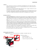
Medium Frame 2 & 3 Stage Snow Throwers ! CAUTION • Be prepared in case of emergency: Keep a fire extinguisher nearby Keep a first aid kit nearby Keep emergency contact numbers handy • Replace any missing or damaged safety labels on shop equipment. • Replace any missing or damaged safety labels on equipment being serviced. • Grooming and attire: ! WARNING Do not wear loose fitting clothing that may become entangled in equipment. Long hair should be secured to prevent entanglement in equipment.
Introduction Fasteners • Most of the fasteners used on these snow throwers have SAE thread sizes.The engines have metric thread sizes. For this reason, wrench sizes are frequently identified in the text, and measurements are given in U.S. and metric scales. • If a fastener has a locking feature that has worn, replace the fastener or apply a small amount of releasable thread locking compound such as Loctite® 242 (blue). • Some fasteners, like cotter pins, are single-use items that are not to be reused.
Medium Frame 2 & 3 Stage Snow Throwers 600 Series The 600 series features: • Solid drive wheel axles • Auger housing width of 22” - 30” • 2 stage augers Figure 1.2 700 Series The 700 series features: • Track drive (2 and 3 wheel versions) • Auger housing width of 24” - 30” • 2 stage and 3 stage augers available. Figure 1.3 Understanding Model And Serial Numbers The model and serial numbers are located on a white sticker with a bar code.
Introduction The model number is 31AH64FG795. The break down of what the model number means is as follows: • 31 - - - - - - - - - - - - - - - - - - - - - - - - Indicates that this is a snow thrower.
Medium Frame 2 & 3 Stage Snow Throwers 6
Belts and Cables Chapter 2: Belts And Cables Auger Belt To remove/replace the Auger Belt: NOTE: Prior to servicing or replacing any belts stop the engine and allow it to cool. Then disconnect spark plug and ground it to the engine 3/8” Hex Screws NOTE: If the unit is throwing the Auger Belt, inspect the round part of the Auger Housing that the impeller spins in. If there is a buckle or a crease in it, the Auger Housing is bent and must be replaced before replacing the belt. 1.
Medium Frame 2 & 3 Stage Snow Throwers 3. Loosen the idler pulley enough for the belt to clear it using a 1/2” wrench. 4. Slip the belt off of the engine pulley. Figure 2.3 5. Drain the fuel into an approved container. 6. Carefully tip the snow thrower forward so it rests on the auger housing. 7. Remove the bottom access panel. See Figure 2.4. 3/8” wrench Figure 2.4 8. Remove the belt guide (the shoulder bolt) with a 3/ 4” wrench and a 9/16” wrench. See Figure 2.5. 9.
Belts and Cables NOTE: On 2005 through 2007 model years, the Return Spring hooked into a hole in the impeller housing. See Figure 2.6. NOTE: The idler bracket has a tab that acts as a brake, pressing against the Auger Belt whenever the Auger Control Lever is released. Return Spring Figure 2.6 10. Pull the belt down past the Auger Pulley. See Figure 2.7. 11. Install the belt by following the previous steps in reverse order. 12. Start the engine. 13.
Medium Frame 2 & 3 Stage Snow Throwers Drive Belt To remove/replace the drive belt: NOTE: Prior to servicing or replacing any belts, stop the engine and allow it to cool. Then disconnect spark plug and ground it to the engine 1. Remove Auger Belt as described on the Auger Belt section of this chapter. 2. Using a 3/8” wrench, rotate the Drive Idler Bracket enough slip the belt off of the engine pulley. See Figure 2.8. Torsion Spring Drive Idler Bracket Figure 2.8 3.
Belts and Cables Auger Control Cable To remove/replace the Auger Control Cable: NOTE: The auger control is on the left side of the handle bars. 1. Place an alignment mark on the adjustment bracket and the frame. See Figure 2.10. 2. Loosen the hex screws securing the adjustment bracket to release tension off of the cable. 3. Detach the cable from the control handles. See Figure 2.11. Alignment mark Figure 2.10 NOTE: On units with threaded Z-fittings: • Loosen the jam nut.
Medium Frame 2 & 3 Stage Snow Throwers 7. Detach the spring end of the cable from the Idler Pulley Bracket. See Figure 2.13. 8. Install the cable by following the previous steps in reverse order. NOTE: When attaching he spring end of the cable, the open side of the spring faces the engine. 9. Test run the snow thrower in a safe area before returning it to service. Idler Pulley Bracket Auger Cable Figure 2.
Belts and Cables Drive Clutch Control Cable To remove/replace the Drive Control Cable: NOTE: The drive control is on the right handle. alignment mark 1. Stop the engine and allow it to cool. Disconnect the spark plug wire and ground it to the engine. 2. Drain the fuel into an approved container. 3. Carefully tip the snow thrower forward so it rests on the auger housing opening. 4. Place an alignment mark on the adjustment bracket and the frame. See Figure 2.14. 5.
Medium Frame 2 & 3 Stage Snow Throwers Auger and Drive Cable Adjustments (500, 600 and 3-wheel Track Drives) NOTE: Prior to servicing or replacing any belts, stop the engine and allow it to cool. Then disconnect spark plug and ground it to the engine 1. Loosen the hex screws that secure the bracket that guides the cable needing adjustment using a 3/8” wrench. See Figure 2.16. 2. Slide the bracket up to add slack to the cable or down to add tension to the cable.
Belts and Cables Auger Cable Adjustments (2-wheel Track Drives) Check the adjustment of the auger control: 1. When the Auger Control Lever is released, in the disengaged or “up” position, the cable should have very little slack. It should not be tight. 2. In a well-ventilated area, start the snow thrower engine. 3. While standing in the operator’s position, behind the snow thrower, engage the auger. 4. Allow the auger to remain engaged for approximately ten seconds before releasing the auger control.
Medium Frame 2 & 3 Stage Snow Throwers Speed Selector Cable To adjust the Speed Selector Cable: NOTE: Inspect the drive platter and friction wheel before adjusting the speed sector cable. Ensure that the friction wheel can freely travel through the whole range of positions. NOTE: A damaged or binding friction wheel can mimic a speed selector cable that is out of adjustment. 1. Place the shift lever in the fastest forward speed position. 2.
Belts and Cables 7. Loosen the cable screw and nut enough to free the zfitting from the from the Speed Control Pivot Bracket. See Figure 2.21. 8. Remove the hair pin clip from the cable end. See Figure 2.22. Screw Nut Figure 2.21 Hair pin clip Figure 2.22 NOTE: Early production units have a hex screw securing the barrel side of the cable to the shifter handle. NOTE: The bracket securing the cable to the shift lever is two pieces 9.
Medium Frame 2 & 3 Stage Snow Throwers Speed Selector Rod To adjust the Speed Selector Rod: NOTE: Inspect the drive platter and friction wheel before adjusting the Speed Selector Cable. Ensure that the friction wheel can freely travel trough the whole range of positions. NOTE: A damaged or binding friction wheel can mimic a speed selector cable that is out of adjustment. 1. Place the Speed Selector Lever in the fastest forward speed position. 2.
Belts and Cables To remove/replace the Speed Selector Rod: 1. Place the shift lever in the fastest forward speed position. 2. Remove the hair pin clip and washer from the upper end of the Selector Rod. See Figure 2.26. 3. Slide the ferrule out of the Speed Selector Lever. 4. Remove the nut that secures the ball joint on the end of the selector rod to the selector assembly, using a 1/2” wrench. See Figure 2.27. 5. Slide the ball joint out of the Selector Assembly. 6.
Medium Frame 2 & 3 Stage Snow Throwers Auger and Drive Lever Interlock To remove/service the Auger And Drive Lever Interlock: 1. Loosen, but do not remove the two screws holding the auger cable using a 3/8” socket. See Figure 2.28. NOTE: Place an alignment mark on the adjustment bracket and the frame for reassembly. Alignment marks Figure 2.28 2. Remove the Z-fitting from the Auger Control Lever with a pair of needle nose pliers. 3. Remove the shoulder bolt using a 3/4” wrench and a 1/2” wrench.
Belts and Cables NOTE: The pivot rod for early production models were nail headed. Current production models have a powered medal end. See Figure 2.31. Nail headed Powdered metal end Figure 2.31 Shoulder nut Hex key NOTE: The shoulder nuts are attached to the clutch lock cams with a socket head screw. The screw can be removed using a 3/16” hex key. NOTE: If the socket head screw is over torqued, the screw head will sink into the plastic material of the Clutch Lock Cam.
Medium Frame 2 & 3 Stage Snow Throwers 22
500 Series Drive System Chapter 3: 500 Series Drive System Axle Assemblies Axle Shafts NOTE: Units with steerable drive wheels have a split axle to allow each wheel to be driven independently of each other. See Figure 3.1. Axle Support Tube Figure 3.1 Axle To remove the axles: 1. With the engine stopped and allowed to cool, disconnect the spark plug wire and ground it to the engine. 2. Drain the fuel into an approved container. 3.
Medium Frame 2 & 3 Stage Snow Throwers 5. Remove the wheels using a 1/2” wrench. NOTE: The ends of the axle shafts are a double-D. See Figure 3.3. Figure 3.3 6. Slide the spacers off of the axle. See Figure 3.4. Spacer Hex Bushing Figure 3.4 7. Carefully pry the 2 split bushings from the axle. See Figure 3.5. Figure 3.
500 Series Drive System 56 tooth gear 8. Slide one of the large 56T gears inward, while gently pulling the axle outward enough to expose the key that engages the gear. See Figure 3.6. 9. Remove the key. 10. Hold the axle support tube and pull the shaft from the housing. 11. Spacer Woodruff key Figure 3.6 Repeat steps 8 through 10 for the opposite axle.
Medium Frame 2 & 3 Stage Snow Throwers Hex Drive Shaft To remove/replace a Hex Drive Shaft: 1. Stop the engine and allow it to cool, disconnect the spark plug wire and ground it to the engine. 2. Drain the fuel into an approved container. 3. Carefully tip the snow thrower forward, so it rests on the auger housing opening. 4. Remove the access panel using 3/8” wrench. 5. Remove both wheels using a 1/2” wrench. 6.
500 Series Drive System Planetary Gears 1. To inspect or repair the planetary gears. it is not necessary to completely remove the drive assembly from the snow thrower. 2. Stop the engine and allow it to cool, disconnect the spark plug wire and ground it to the engine. 3. Drain the fuel into an approved container. 4. Carefully tip the snow thrower forward so it rests on the auger housing opening. 5. Remove the wheel using a 1/2” wrench. 6.
Medium Frame 2 & 3 Stage Snow Throwers 10. Inside of each planetary gear set is a series of planetary gears that rotate around a sun gear and rotate inside of the ring gear. See Figure 3.13. Planetary gears Sun Gear NOTE: The groves are grease grooves. 11. Although the planetary gears rarely have any service issues, a good working knowledge is important. • The hex shaft transfers torque from the rubber drive disc to the sun gear on each end of the hex drive shaft.
500 Series Drive System Friction Wheel Replacement To remove/replace the Friction Wheel: 1. Remove the Hex Drive Shaft by following the procedures described in the Hex Drive Shaft section of this chapter. 2. Remove the bearing from one side of the Hex Drive Shaft. 3. Remove the snap ring that holds the planetary gear set to the Hex Drive Shaft. 4. Slide the planetary gear set off of the Hex Drive Shaft. 5. Slide the Friction Wheel Assembly off of the hex shaft. 6.
Medium Frame 2 & 3 Stage Snow Throwers 30
600 Series Drive System Chapter 4: 600 Series Drive System Axle Assemblies 1. With the engine stopped and allowed to cool, disconnect the spark plug wire and ground it to the engine. 2. Drain the fuel into an approved container. 3. Carefully tip the snow thrower forward, so it rests on the auger housing opening. 4. Remove the bottom access panel. See Figure 4.1. 5. Remove the wheels using a 1/2” wrench. Figure 4.1 NOTE: The ends of the axle shaft are double D. Figure 4.
Medium Frame 2 & 3 Stage Snow Throwers 6. Slide the spacers and washers off of the axle. See Figure 4.3. NOTE: There are usually 2 washers on the left side and only 1 on the right side. Spacer Hex Bushing Washers Figure 4.3 7. Remove the E-rings from the axle shaft. NOTE: Starting in 2013, the E-rings were removed and replaced with a 7” long split spacer. 8. Slide the axle to the left until the woodruff key in the axle is fully exposed. See Figure 4.4. 9. Remove the woodruff key.
600 Series Drive System Hex Drive Shaft Assembly To remove/replace the Hex Drive Shaft Assembly: 1. Remove the Axle Assembly as described in Axle Assemblies section of this chapter. 2. Remove the E-ring from the left side of the drive shaft assembly. See Figure 4.6. 3. Remove the bolt or nut, depending on production date, from the end of the hex shaft using a 9/16” wrench while holding the shaft with a 13/16” wrench. See Figure 4.7. Figure 4.6 9/16” Wrench NOTE: Some units may have a 3/4” hex shaft.
Medium Frame 2 & 3 Stage Snow Throwers 4. Rotate the friction wheel assembly until the collar is free from the pin on the shift assembly. 5. Maneuver the shaft partially through the wheel drive frame, then tilt the assembly forward to free it from the housing. See Figure 4.9. 6. Examine the removed parts: if any failed because of something other that normal wear, identify and correct the cause before returning the snow thrower to service. 7.
600 Series Drive System Friction Wheel Replacement 1. Remove the drive shaft by following the procedures described in the Hex Drive Shaft Assembly section of this chapter. 2. Remove the bearing from one end of the shaft. 3. Slide the Friction Wheel Assembly off of the shaft. NOTE: On the single speed models, drive out the roll pin holding the friction wheel to the hex shaft. Roll pin Figure 4.10 4. Remove the four screws that hold the Friction Wheel Assembly together using a 1/2” wrench.
Medium Frame 2 & 3 Stage Snow Throwers 6. Inspect the parts for damage or wear. 7. Install the rubber Friction Wheel by following the previous steps in reverse order. NOTE: Tighten the screws in a star pattern. See Figure 4.12. NOTE: The torque for the 1/4”-20 screws is 72 - 108 in lbs (8 - 12 Nm). 3 2 1 4 NOTE: The torque for the 5/16”-18 screws is 115 145 in lbs (13 - 16 Nm) NOTE: Make sure the rubber ring is secure within the wheel assembly before installing it in the unit.
700 Series 2-Wheel Track-Drive System Chapter 5: 700 Series 2-Wheel Track-Drive System Track Adjustment To adjust track: Bottom of track Note the direction of the Track Tread Pattern. 1. Disconnect the spark plug wire from the spark plug and ground against engine. 2. Drain fuel from fuel tank. NOTE: The tension on the tracks of the snow thrower can be adjusted. There are track adjusters on each side of the unit. It is important that each track is adjusted equally. J-bolt Front of snow thrower 3.
Medium Frame 2 & 3 Stage Snow Throwers Track and Track Wheels To remove/replace the Track and Track Wheels: Drive wheel NOTE: The Track and Track Wheels are removed and installed as one assembly. 1. Disconnect spark plug wire from spark plug and ground it against the engine. 2. Drain the fuel tank. 3. Tip the snow thrower forward, so that it rests on its auger housing opening. 4. Remove the nut and washer from the drive wheel using a 3/4” wrench. See Figure 5.2. Figure 5.2 5.
700 Series 2-Wheel Track-Drive System Hex Drive Shaft To remove/replace the Hex Drive Shaft: 1. Stop the engine and allow it to cool, disconnect the spark plug wire and ground it to the engine. 2. Drain the fuel tank into an approved container. 3. Carefully tip the snow thrower forward so it rests on the auger housing opening. 4. Remove the access panel using 3/8” wrench. See Figure 5.5. 5. Hold the Hex Drive Shaft with a 3/4” wrench. See Figure 5.6. Figure 5.
Medium Frame 2 & 3 Stage Snow Throwers 8. Remove the Patch Bolt and washer that secures the left Hex Drive Shaft Bearing. See Figure 5.8. 9. Remove the bearing and spacer. Patch bolt Figure 5.8 10. Slide the Hex Drive Shaft out of the unit from the right side. See Figure 5.9. NOTE: The Friction Wheel Assembly is now free. Inspect and replace the Friction Wheel if there are any signs of wear or damage. Figure 5.9 To install the Hex Drive Shaft: 11.
700 Series 2-Wheel Track-Drive System 12. Slide the Hex Drive Shaft into the frame from the right side, passing it through the Friction Wheel Assembly. NOTE: The side without the E-ring goes in first. Figure 5.11 13. Align the Hex Drive Shaft with the sprocket. 14. Pass the Hex Drive Shaft through the sprocket until the E-ring on the shaft rests against the Friction Wheel. See Figure 5.12. Sprocket Figure 5.12 15. Install the spacer on the left side of the Hex Drive Shaft. See Figure 5.13. 16.
Medium Frame 2 & 3 Stage Snow Throwers 19. Install the bearing on the right side. See Figure 5.14. 20. Install the Patch Bolt and washer. 21. Place a small amount of 3-in-1, or similar oil, on a rag. Wipe a light coating of oil on the Hex Drive Shaft. 22. Install the access panel. 23. Test run the unit in a safe area before returning it to service. Right bearing Figure 5.
700 Series 2-Wheel Track-Drive System Friction Wheel Replacement To remove/replace the Friction Wheel: 1. Remove the Hex Drive Shaft by following the procedures described in the Hex Drive Shaft section of this chapter. 2. Slide the Friction Wheel Assembly off of the pin on the Shift Arm. See Figure 5.15. 3. Remove the four screws that hold the Friction Wheel Assembly together, using a 1/2” wrench. Shift Arm Figure 5.15 NOTE: Earlier production units require a 3/8” wrench for the four screws. 4.
Medium Frame 2 & 3 Stage Snow Throwers Axle Shaft To remove/replace an Axle Shaft: 1. Remove the Track and Track Wheels of the affected axle by following the procedures described in the Track and Track Wheels section of this chapter. 2. Remove the bottom access panel. 3. Remove the eight screws that hold the rear aluminum housing in place, using a 1/2” wrench. See Figure 5.18. 4. Lift the housing out of the snow thrower. Figure 5.18 5.
700 Series 2-Wheel Track-Drive System 11. Drive out the old bushings using a drift punch. See Figure 5.21. Figure 5.21 12. Install new bushings in the axle tube. 13. Set the axle tube in place. 14. Slip the chain over the axle tube. 15. Slide the axle into the axle tube. Figure 5.22 16. With the teeth of the sprocket gears next to each other, slip the chain onto both sprockets. 17. Install the two screws that hold the axle tube in place. 18.
Medium Frame 2 & 3 Stage Snow Throwers Planetary Gears and Shaft To remove/replace the planetary gears and shaft: 1. 2. Slip the chains off of both axles by following the procedures described in the Axle Shaft section of this chapter. Triggers Clamp down both steering triggers. See Figure 5.24. Figure 5.24 3. Drive out the roll pin using a 5/32” pin punch. See Figure 5.25. Figure 5.25 4. Remove the nut and washer on each end of the Planetary Shaft. See Figure 5.26. 5.
700 Series 2-Wheel Track-Drive System 6. Slide the Planetary Shaft to the right enough for it to clear the transmission housing. See Figure 5.27. 7. Slip the drive chain off of the sprocket on the end of the shaft. 8. Remove the Planetary Shaft Assembly from the transmission box. 9. Set the shaft on the work bench. See Figure 5.28. Figure 5.27 10. Slide the sprocket off of the shaft. 11. Remove both chains. Figure 5.28 12. Remove the shim washers. 13.
Medium Frame 2 & 3 Stage Snow Throwers 14. Remove the Sun Gear. See Figure 5.30. 15. Remove the Ring Gear and washer. Ring Gear Planetary Gears Sun Gear Figure 5.30 16. Remove the snap ring from the right Planetary Gear Set. See Figure 5.31. 17. Remove the shim washers. 18. Slide the right Planetary Gear Carrier off of the shaft. 19. Remove the Sun Gear. 20. Remove the Ring Gear and washer. 21. Clean and inspect all of the components.
700 Series 2-Wheel Track-Drive System 23. Grease the needle bearing and the planetary gear posts on the carrier with Arctic Grease (737-0318CRTG). See Figure 5.33. 24. Install the planetary gears on the carrier. NOTE: The grooves on the planetary gears are for grease. They are not timing marks. Figure 5.33 25. Slide the washer, from behind the ring gears, onto the shaft. 26. Grease the splines and the part of the shaft where the needle bearings ride with Arctic Grease (7370318-CRTG). See Figure 5.34. 27.
Medium Frame 2 & 3 Stage Snow Throwers 36. Measure the free travel of each Planetary Gear Set using a feeler gauge. NOTE: There should be 0.010” - 0.030” travel. NOTE: If there is too much travel, add a 0.020” shim, part number 936-0502. If there is not enough travel remove a shim. 37. Remove the roll pin, but leave the sprocket on the shaft. NOTE: Installing the drive chain, with the roll pin in place, is very difficult. 38.
700 Series 2-Wheel Track-Drive System Steering Trigger Cables To remove/replace a steering trigger cable: E-ring 1. Disconnect the spark plug wire from spark plug and ground it against the engine. 2. Drain the fuel tank into an approved container. 3. Tip the snow thrower forward so that it rests on its auger housing opening. 4. Remove the E-ring that secures the steering trigger’s Pivot Pin. See Figure 5.37. 5. Remove the Pivot Pin. 6. Unhook the trigger from the cable. See Figure 5.38. 7.
Medium Frame 2 & 3 Stage Snow Throwers 8. Remove the bottom access panel. 9. Remove the eight screws that hold the rear aluminum housing in place, using a 1/2” wrench. See Figure 3.40. 10. Lift the housing out of the snow thrower. Figure 3.40 11. Squeeze the tabs on the end of the cable. See Figure 5.41. Tabs Planetary pawl Figure 5.41 NOTE: A Ford fuel line tool is useful for squeezing the tabs on the end of the cable. See Figure 5.42. 12. Pull the cable out of the rear plate. 13.
700 Series 3-Wheel Track-Drive System Chapter 6: 700 Series 3-Wheel Track-Drive System Track Removal/replacement To remove/replace the Tracks: NOTE: There is a spring loaded idler on both tracks, that will take up the slack in the Tracks as they stretch. Both of the spring loaded idlers need to be held down when doing any work or adjustments to the Tracks. Instructions on how to build a set of tools to hold the idlers down are located at the end of this chapter. See Figure 6.1. 1.
Medium Frame 2 & 3 Stage Snow Throwers 5. Remove the four screws that hold the bottom access panel in place using a 3/8” wrench. 6. Slide the panel out from under the top of the frame. 7. Rotate the panel until it is perpendicular to the frame and slide it out of the slot in the frame. See Figure 6.3. Figure 6.3 8. Remove the nuts from the tensioning J-bolts using a 1/2” wrench. See Figure 6.4. Tensioning J-bolts NOTE: The J-bolts will fall out when the Rear Wheel retaining nuts are removed.
700 Series 3-Wheel Track-Drive System Rear Wheel 10. Slide the Rear Wheel off of the Rear Axle. See Figure 6.6. 11. Remove the Rear Wheel. 12. Lift the Track off of the machine. 13. Repeat on the opposite side. Figure 6.6 To install the tracks: Rear Axle 1. If the Rear Axle fell out, set the it on the machine so that the flanges are inside the slots in the Track Frame. See Figure 6.7. 2. With the idler hold-down tools still in place, set the Track on the drive wheel and Front Wheel.
Medium Frame 2 & 3 Stage Snow Throwers 3. Place the Rear Wheel into its groove in the Track. 4. Slide the Rear Wheel onto the Rear Axle with the Track. See Figure 6.9. 5. Install the retaining nut a couple of threads deep. Groove IMPORTANT: Do not tighten the nut. 6. Repeat steps 2 through 5 on the opposite Track. Figure 6.9 Quick Grip bar clamps 7. Lift the rear axle evenly to install the J-bolts. NOTE: A pair of Quick Grip bar clamps in spreading mode work well for this. See Figure 6.10. 8.
700 Series 3-Wheel Track-Drive System 11. Measure the Track tension: NOTE: Track tension must be checked with the Tracks off of the ground. Pressure reading 11a. Lay a straight edge across the section of Track between the Drive Wheel and the Rear Wheel. 11b. With the idler hold-down tools installed, measure the amount of force required to cause 3/8” deflection. See Figure 6.12. • The reading should be 14 - 20 lbs. • If the reading is too low, tighten both Tracks evenly.
Medium Frame 2 & 3 Stage Snow Throwers Track Drive Assembly To remove/replace the Track Drive Assembly: 1. Remove the Tracks by following the procedures described in the Track removal/replacement section of this chapter. 2. Remove the screw that secures the Drive Wheel to the drive axle using a 1/2” wrench.Figure 6.13. Drive Wheel NOTE: Engaging the Drive Control Lever will help hold the axle while removing the screw that secures the Drive Wheel. 3. Slide the Drive Wheel off of the axle. 4.
700 Series 3-Wheel Track-Drive System Drive Axle Assemblies To remove the Drive Axles: Split bushings 1. Remove the Tracks by following the procedures described in the Track removal/replacement section of this chapter. 2. Remove the Track Drive Assemblies by following the procedures described in the Track Drive Assemblies section of this chapter. 3. Remove the Split Bushings from the Drive Axle 4.
Medium Frame 2 & 3 Stage Snow Throwers Hex Drive Shaft and Planetary Gears To remove the Hex Drive Shaft: 1. Remove the Drive Axles by following the procedures described in the previous section of this chapter. 2. Clamp down both Steering Triggers. See Figure 6.19. Triggers Figure 6.19 3. Remove the four screws that hold the left side Retainer Housing. See Figure 6.20. Shaft Retainer Housing Figure 6.20 4. Rotate the entire Friction Wheel Assembly backwards to free the pin from the Shifter Arm.
700 Series 3-Wheel Track-Drive System Thin Washer Thick Washer 6. Remove the bearing and washers. NOTE: Keep track of the order of the washers for reassembly. See Figure 6.22. Bearing Figure 6.22 7. Carefully remove the E-ring that secures the Planetary Set. See Figure 6.23. 8. Slide the Planetary Gears Set off of the Hex Drive Shaft. 9. Remove the washer that was behind the Gear Set. E-ring Figure 6.23 Thinest washer NOTE: The washer behind the Gear Set is the thinnest of the three washers.
Medium Frame 2 & 3 Stage Snow Throwers 12. Inside of each Planetary Gear Set is a series of Planetary Gears that rotate around a Sun Gear and rotate inside of the Ring Gear. See Figure 6.25. Planetary Gears NOTE: The groves are grease grooves. 13. Although the Planetary Gears rarely have any service issues, a good working knowledge is important. • The Hex Drive Shaft transfers torque from the Friction Wheel to the Sun Gear on each end of the Hex Drive Shaft.
700 Series 3-Wheel Track-Drive System Friction Wheel Replacement To remove/replace the Friction Wheel: 1. Remove the Hex Drive Shaft by following the procedures described in the Hex Drive Shaft section of this chapter. 2. Remove the bearing and washers from one side of the Hex Drive Shaft. 3. Remove the E-ring that holds the Planetary Gear Set to the Hex Drive Shaft. 4. Slide the Planetary Gear Set and washer off of the Hex Drive Shaft. See Figure 6.28.
Medium Frame 2 & 3 Stage Snow Throwers Idler Hold Down Tools Two tools are needed to hold down the spring loaded idlers. The components needed to assemble the tools are: • (2) forked angle brackets (50 x 55 mm). • (2) angle brackets (45 x 55mm). • (2) 5.25” x 1” x 0.25” pieces of flat stock steel. • (8) 1/4” x 20 x 5/8” bolts • (8) 1/4” x 20 nuts Bolt heads NOTE: The print for the angle brackets and the flat stock is on the next page.
15 mm 65 mm NOTE: All holes are 0.25” 28 mm 15 mm 25 mm 20 mm 50 mm 27.5 mm 15 mm 12.5 mm 10 mm 1” 4 mm 44 mm Flat stock should be 0.25” thick 27 mm 11 mm 11 mm 11 mm 45 mm 55 mm 11 mm 2 Angle brackets. 10 gauge steel minimum 45 mm 12.5 mm 15 mm 2 Angle brackets. 10 gauge steel minimum 700 Series 3-Wheel Track-Drive System 50 mm 65 5.
Medium Frame 2 & 3 Stage Snow Throwers 66
Auger Housing and Gear Box Chapter 7: Auger Housing and Gear Box NOTE: The Shave Plate and Skid Shoes on the bottom of the snow thrower are subject to wear. They should be checked periodically and replaced when necessary. Skid Shoes Reversible Reversible NOTE: There is a variety of Skid Shoes available for medium frame snow throwers. Most of them are reversible. See Figure 7.1. To remove the Skid Shoes: Reversible Non-Reversible Figure 7.1 1.
Medium Frame 2 & 3 Stage Snow Throwers Shave Plate To remove/replace the Shave Plate: 1. Drain the fuel from the fuel tank. 2. Tip the snow thrower back enough to access the shave plate. NOTE: Laying the snow thrower on its back will cause the engine cylinder to fill with oil. 3. Remove the nuts and carriage bolts (indicated by the arrows in Figure 7.3.) that hold the Shave Plate to the Auger Housing using a 1/2” wrench. Figure 7.
Auger Housing and Gear Box Auger Housings To remove/replace the Auger Housing: 3/8” Hex Screws 1. Disconnect and ground the spark plug wire. 2. Remove the Discharge Chute by following the procedures described in appropriate discharge chute chapter. 3. Remove the two screws that secure the belt cover using a 3/8” wrench. See Figure 7.5. 4. Lift the Belt Cover off of the unit. 5. Loosen the Idler Pulley enough for the belt to clear it using a 1/2” wrench. See Figure 7.6. 6.
Medium Frame 2 & 3 Stage Snow Throwers NOTE: On 2-Wheel Track units: • Remove the six nuts that hold the Auger Housing to the transmission box using a 1/2” wrench. See Figure 7.8. 8. Separate the Auger Housing from the transmission box. 9. Disconnect the Auger Control Cable from the Idler Bracket. 10. Remove the Auger Gear Box Assembly by following the procedures described in the Auger Assemblies removal section of this chapter. Figure 7.8 11.
Auger Housing and Gear Box Auger Assemblies To remove/replace the Auger Assembly: NOTE: The procedures for removing/replacing the Auger Assemblies are basically the same for a 2-stage and a 3-stage unit. Any differences will be covered when they arise. 1. Separate the Auger Housing from the Transmission Box by following the procedures described in the Auger Housing section of this chapter. 2. Remove the Auger Belt. 3. Use a block of wood to prevent the augers from turning. See Figure 7.11. 4.
Medium Frame 2 & 3 Stage Snow Throwers 6. Remove the screws holding the Bearing Housing on each side. See Figure 7.14. NOTE: This is a good opportunity to inspect the Auger Bearing for signs of wear. Figure 7.14 7. Pull the auger from the housing. Slight rotation of the assembly may be necessary to pull the Impeller Shaft clear of the rear bearing. See Figure 7.15. NOTE: The most common cause of Auger GearBox damage is an impact with solid objects. This damage is not warrantable.
Auger Housing and Gear Box NOTE: 3-stage units have augers on the front and back of the Gear Box called Accelerators. See Figure 7.17. 9. Pry off the front cap. 10. Remove the screw and washer from the end of the Input Shaft. 11. Remove the Shear Pin. 12. Slide the Accelerator, washer and spacer off of the front of the Gear Box. Accelerator Figure 7.17 Spacers Hex Bushing 13. Slide the impeller off of the D section of the Gear Box Input Shaft.
Medium Frame 2 & 3 Stage Snow Throwers 2-Stage Gear Boxes To rebuild a 2-stage Gear Box: 1. Remove the Gear Box by following the procedures described in the Auger Assemblies section of this chapter. 2. Gently pry out the Fill Plug. See Figure 7.20. 3. Turn the transmission over and drain any oil into an approved container. Fill Plug NOTE: The transmission is filled with grease, but the grease will break down and release its oil over time. Figure 7.20 4.
Auger Housing and Gear Box 6. Remove the Input Shaft Assembly. 7. Disassemble the Input Shaft Assembly. Input Shaft Figure 7.23 NOTE: The Input Shaft might be a little swollen at the double D, preventing the bushing and collar from sliding off. If necessary, file down the swollen area until the bushing clears. 8. Inspect the shaft, bushings, pin and collar. If there are any signs of wear or damage, replace the affected part(s). 9. Remove the Output Shaft, washers and Worm Gear. Figure 7.
Medium Frame 2 & 3 Stage Snow Throwers 12. Remove the seals from the housings. 13. Thoroughly clean the housings and remove all of the old sealant. 14. Press new seals into the housings. See Figure 7.26. Seal Figure 7.26 15. Reassemble the Output Shaft, Worm Gear and washers. 16. Insert the Output Shaft Assembly into one of the housings. See Figure 7.27. Figure 7.27 17. Reassemble the Input Shaft Assembly with a new seal. 18.
Auger Housing and Gear Box 19. Apply 1.5 - 2 oz of 737-0168A grease to the gears and inside of the housing. See Figure 7.29. 20. Work the gears to distribute the grease between them. Figure 7.29 Thin bead of sealant 21. Apply a small bead of Loctite Ultra Grey, or similar sealant, along the inside of the bolt holes on one of the housings. See Figure 7.30. NOTE: A small bead is all that is needed. A thick bead of sealant is a waste of sealant and can cause excess sealant to get into the bearings. 22.
Medium Frame 2 & 3 Stage Snow Throwers 3-Stage Gear Boxes To rebuild a 3-stage Gear Box: 1. Remove the Gear Box by following the procedures described in the Auger Assemblies section of this chapter. 2. Remove the four screws that secure the cover to the gear box housing using a 3/8” wrench. See Figure 7.31. 3. Gently lift the cover off of the Gear Box. 4. Drain the gear box into an approved container. Cover Figure 7.31 5. Remove the left seal, as viewed from the operator’s position. 6.
Auger Housing and Gear Box 8. Remove the rear Input Shaft (long side) Seal. 9. Remove the snap ring. See Figure 7.34. Snap Ring Figure 7.34 10. Remove the Input Shaft from the rear of the Gear Box. 11. Lift the Worm Gear out of the Gear Box. See Figure 7.35. Worm Gear Figure 7.35 12. Drive out the right side bearing.Figure 7.36. 13. Remove the seal. Figure 7.
Medium Frame 2 & 3 Stage Snow Throwers 14. Drive out the front bearing.Figure 7.37. 15. Remove the seal. 16. Clean and dry all components. 17. Inspect the components. NOTE: If there are signs of wear or damage, replace the affected component(s). Figure 7.37 18. Install the front bearing, using a brass punch to seat it. See Figure 7.38. NOTE: The front Bearing Pocket does not have a snap ring grove, the rear does. Figure 7.38 19. Install the right bearing, using a brass punch to seat it.
Auger Housing and Gear Box 20. Set the Worm Gear inside the housing. See Figure 7.40. Figure 7.40 Short end 21. Insert the Input Shaft into the housing so that the short end rests in the front bearing. See Figure 7.41. 22. Install the rear bearing. Front Bearing Rear Bearing Figure 7.41 23. Install the rear snap ring. See Figure 7.42. Snap Ring Figure 7.
Medium Frame 2 & 3 Stage Snow Throwers 24. Insert the key into the Output Shaft. 25. Insert the Output Shaft into the housing from the left side, passing it through the Worm Gear. See Figure 7.43. 26. Rotate the Output Shaft until the key lines up with the slot in the Worm Gear. 27. Push the shaft into the housing until the key passes into the Worm Gear. 28. Install the left bearing. Figure 7.43 29. Install the left snap ring. See Figure 7.44. 30. Install new seals for all four bearings.
Discharge Chute and Controls (Manual Crank) Chapter 8: Discharge Chute and Controls (Manual Crank) Remote Pitch Control Head (Plastic Chutes) To remove/replace the Remote Pitch Control Head: NOTE: The Remote Pitch Control Head consists of a Cable Guide, Cable Guide Bracket, and the cables that run to the pitch control lever/joystick. 1. Remove the wing nut and carriage bolt that holds the left side of the Chute Deflector to the Discharge Chute. 2. Remove the nut (indicated by the arrow in Figure 8.
Medium Frame 2 & 3 Stage Snow Throwers 5. Slide the Cable Guide out from in between the Cable Bracket and the Discharge Chute. See Figure 8.3. 6. Disconnect the cables from the cable guide. Cable bracket Cable guide Figure 8.3 7. Mark one of the cables and its location in the Cable Bracket. See Figure 8.4. 8. Unhook the cable assemblies from the Chute Deflector. 9. Remove both of the cables. Mark the cable and bracket Figure 8.4 To install the Chute Deflector: 1.
Discharge Chute and Controls (Manual Crank) 4. Attach the cables to the Cable Guide. See Figure 8.6. 5. Slide the Chute Deflector onto the Discharge Chute. NOTE: Do not apply grease to the inside surface of the Chute Deflector or the outside surface of the Discharge Chute. Cable ends 6. Install the carriage bolts and nuts that hold the Chute Deflector to the Discharge Chute. NOTE: Thread the nuts on to the carriage bolts until a couple of threads stick out past the nylon locking feature.
Medium Frame 2 & 3 Stage Snow Throwers Remote Pitch Control Head (Steel Chutes) To remove/attach the Pitch Control Head to/from the Chute Deflector: NOTE: The Remote Pitch Control Head consists of a Cable Guide, Cable Guide Bracket, and the cables that run to the pitch control lever/ joystick. 1. Remove the wing nut, washer and carriage bolt that holds the left side of the Chute Deflector to the Discharge Chute. 2. Remove the nut, indicated by the arrow in Figure 8.
Discharge Chute and Controls (Manual Crank) 8. Disconnect the cables from the Cable Guide. See Figure 8.10. 9. Unhook the Cable Bracket from the Chute Deflector. Figure 8.10 To install the Chute Deflector: 1. Hook the Cable Bracket onto the Chute Deflector. See Figure 8.11. 2. Attach both cables to the Cable Guide. NOTE: Forward movement of pitch control lever/joystick should result in the Chute Deflector moving down. NOTE: If the cables are reversed, the chute operation will be reversed.
Medium Frame 2 & 3 Stage Snow Throwers 5. Set the Chute Wiper in place. 6. Set the Chute Deflector on the chute. Wiper Figure 8.13 7. Align the deflector and the chute by inserting a carriage bolt through the chute, wiper, deflector, Cable Guide and the Cable Bracket. See Figure 8.13. NOTE: Do not apply grease to the inside surface of the Chute Deflector or the outside surface of the Discharge Chute. 8. Install the nut on the carriage bolt installed in the previous step.
Discharge Chute and Controls (Manual Crank) Discharge Chute (Manual Crank, Cork Screw Style) To remove/replace the Discharge Chute: 1. Pry open the three Flange Keepers securing the discharge chute to the chute adapter.Figure 8.15 2. Lift the chute assembly off the mounting base of the main housing. NOTE: If the unit is equipped with remote pitch control, refer to the Remote Pitch Control Head section to remove the control head. To install the chute: Flange Keeper Figure 8.15 1.
Medium Frame 2 & 3 Stage Snow Throwers Discharge Chute (with Remote Head) 1. Remove the hair pin clip that secures the shaft from the hand crank or joystick, if equipped. See Figure 8.16. Hair Pin Clip Figure 8.16 2. Remove the bow tie clip. 3. Remove the clevis pin that holds the Remote Head to the Support Bracket. See Figure 8.17. 4. Remove the wing nut. Bow Tie Clip Wing Nut Figure 8.17 NOTE: Units with a steel chute have a lock nut instead of a wing nut. See Figure 8.18.
Discharge Chute and Controls (Manual Crank) 5. Remove the bolt that secures the Remote Head to the Discharge Chute. See Figure 8.19. 6. The Discharge Chute will lift off of the Chute Collar. See Figure 8.20. 7. Separate the Remote Head from the chute. See Figure 8.21. 8. Install the chute by following the previous steps in reverse order. Figure 8.19 Figure 8.20 NOTE: Some early production units with a remote head had Flange Keepers.
Medium Frame 2 & 3 Stage Snow Throwers Manual Crank, Cork Screw Style To remove/replace the Chute Crank: 1. Remove the flat washer and hair pin clip from the end of the Chute Crank. See Figure 8.22. 2. Remove the wing nut from the eye bolt that attaches the crank to the handle. 3. Slide the eye bolt out of the handle 4. Pull the crank out of the Chute Bracket. 5. Install the crank by following the previous steps in reverse order. 6.
Discharge Chute and Controls (Manual Crank) Remote Head To disassemble a manual crank Remote Head: NOTE: Procedures for rigid and flexible shaft Remote Heads are the same. Figure 8.24 1. Remove the hair pin clip that attaches the crank to the Remote Head. 2. Slide the shaft out of the Remote Head. 3. Remove the bolt that attaches the Remote Head to the chute using a 1/2” wrench. See Figure 8.24. 4. Remove the wing nut from the underside of the Remote Head. 5.
Medium Frame 2 & 3 Stage Snow Throwers 8. Move the remote head to a workbench for service. 9. Remove the four screws that hold the Gear Support to the cover using a 5/16” wrench. See Figure 8.27. Figure 8.27 10. Lift the Gear Set out of the Remote Head Cover. See Figure 8.28. 11. Lift the Pinion Gear out of the Gear Set. Pinion Gear Figure 8.28 12. Lift the Worm Gear and shaft out of the Gear Support Bracket. See Figure 8.29. 13. Remove the Pinion Gear Bushing. Worm Gear Figure 8.
Discharge Chute and Controls (Manual Crank) 14. Insert a pick or similar tool into the hole in the Gear Shaft while removing the nut with a 9/16” wrench. See Figure 8.30. Figure 8.30 15. Remove the hex bushings, spring and washers from the shaft. Figure 8.31 To assemble the Remote Head: Hole 1. Slide the Worm Gear onto the Gear Shaft so that the alignment mark is facing and is aligned with the holes in the gear shaft. NOTE: Slide the gear onto the shaft from the side with the holes.
Medium Frame 2 & 3 Stage Snow Throwers 2. Install the large holed washers and hex bushings onto the gear shaft. 3. Install the small holed washers and the spring onto the Gear Shaft. 4. Install the lock nut. Tighten it to a torque of 35 - 50 in lbs (4 - 6 Nm). See Figure 8.33. Figure 8.33 5. Install the Pinion Bushing in the Gear Support Bracket. 6. Install the Gear Shaft Assembly into to Support Bracket. 7. Test the Gear Shaft for binding.
Discharge Chute and Controls (Joystick, Cable Style) Chapter 9: Discharge Chute and Controls (Joystick, Cable Style) Remote Pitch Control Head (Plastic Chutes) To remove/replace the Pitch Control Head: NOTE: The Remote Pitch Control Head consists of a Cable Guide, Cable Guide Bracket, and the cables that run to the pitch control lever/joystick. 1. Remove the wing nut and carriage bolt that holds the left side of the Chute Deflector to the Discharge Chute. 2.
Medium Frame 2 & 3 Stage Snow Throwers 5. Slide the Cable Guide out from in between the Cable Bracket and the Discharge Chute. See Figure 9.3. 6. Disconnect the cables from the Cable Guide. Cable Bracket Cable Guide Figure 9.3 7. Unhook the cable assembly from the Chute Deflector. 8. Mark one of the cables and its location in the Cable Bracket. See Figure 9.4. 9. Remove both of the cables. Mark the cable and bracket Figure 9.4 To install the Chute Deflector: 1.
Discharge Chute and Controls (Joystick, Cable Style) 4. Attach the cables to the Cable Guide. See Figure 9.6. 5. Slide the Chute Deflector onto the Discharge Chute. NOTE: Do not apply grease to the inside surface of the Chute Deflector or the outside surface of the Discharge Chute. Cable ends 6. Install the carriage bolts and nuts that hold the Chute Deflector to the Discharge Chute. NOTE: Thread the nuts on to the carriage bolts until a couple of threads stick out past the nylon locking feature.
Medium Frame 2 & 3 Stage Snow Throwers Discharge Chute (with Remote Head) 1. Remove the pitch control by following the procedures in the Remote Pitch Control Head section of this chapter. 2. Remove the bow tie clip. 3. Remove the clevis pin that holds the Remote Head to the Support Bracket. See Figure 9.7. 4. Remove the wing nut. Wing Nut Bow Tie Clip Figure 9.7 5. Remove the bolt that secures the Remote Head to the Discharge Chute. See Figure 9.8. Figure 9.8 6.
Discharge Chute and Controls (Joystick, Cable Style) 7. Separate the Remote Head from the chute. See Figure 9.10. 8. Install the chute by following the previous steps in reverse order. NOTE: Some early production units with a remote head had Flange Keepers. If there were Flange Keepers on the discharge chute remove and discard them. Do not install them when installing the chute. 9. Separate Test run the snow thrower in a safe area before returning it to service. Figure 9.
Medium Frame 2 & 3 Stage Snow Throwers Joystick (Cable Style) To remove/replace the joystick: NOTE: The Remote Head and cables are part of the joystick and can not be serviced separately. NOTE: The procedures described here will cover the 2-way and the 4-way joystick. 1. Remove the bow tie clip from the clevis pin that holds the pivoting assembly to the support bracket. See Figure 9.11. 2. Remove the wing nut and screw directly in front of the clevis pin, Bow Tie Clip Wing Nut Figure 9.11 3.
Discharge Chute and Controls (Joystick, Cable Style) 6. Remove the six screws that fasten the joystick to the dash with a 3/8” wrench. See Figure 9.14. NOTE: Folding the handle bars down will allow easier access to the joystick assembly. Mounting bracket 7. Remove the joystick and its mounting bracket. 8. Install the joystick by following the previous steps in reverse order. NOTE: Unwind the cables prior to attaching them to the snow thrower. Allow the cables to flow without tangling or twisting.
Medium Frame 2 & 3 Stage Snow Throwers 104
Discharge Chute and Controls (Joystick, Hex Shaft) Chapter 10: Discharge Chute and Controls (Joystick, Hex Shaft) Remote Pitch Control Head (Plastic Chutes) To remove/replace the Remote Pitch Control Head: NOTE: The Remote Pitch Control Head consists of a Cable Guide, Cable Guide Bracket, and the cables that run to the pitch control lever/joystick. 1. Remove the wing nut and carriage bolt that holds the left side of the Chute Deflector to the Discharge Chute. 2.
Medium Frame 2 & 3 Stage Snow Throwers 5. Slide the Cable Guide out from in between the Cable Bracket and the Discharge Chute. See Figure 10.3. 6. Disconnect the cables from the Cable Guide. Cable Bracket Cable Guide Figure 10.3 7. Mark one of the cables and its location in the Cable Bracket. See Figure 10.4. 8. Unhook the cable assembly from the Chute Deflector. 9. Remove both of the cables. Mark the cable and bracket Figure 10.4 To install the Chute Deflector: 1.
Discharge Chute and Controls (Joystick, Hex Shaft) Cable ends 4. Attach the cables to the Cable Guide. See Figure 10.6. 5. Slide the Chute Deflector onto the Discharge Chute. NOTE: Do not apply grease to the inside surface of the Chute Deflector or the outside surface of the Discharge Chute. 6. Install the carriage bolts and nuts that hold the Chute Deflector to the Discharge Chute. NOTE: Thread the nuts on to the carriage bolts until a couple of threads stick out past the nylon locking feature.
Medium Frame 2 & 3 Stage Snow Throwers Remote Head (Joystick, Hex Shaft) To disassemble the Remote Head: 1. Remove the two screws, indicated by the arrows in Figure 10.7, from the grip assembly using a #2 Phillips screwdriver. 2. Slide the grip assembly off of the metal lever. Figure 10.7 3. Remove the final screw with the grip held in a horizontal position. See Figure 10.8. • A wedge on the trigger fits into a recess in the guide.
Discharge Chute and Controls (Joystick, Hex Shaft) 11. Separate here Separate the Remote Head from the chute. See Figure 10.10. Figure 10.10 Flat washer NOTE: There is a flat washer between the Remote Head and the chute. If this washer is missing, the Remote Head may bind up. See Figure 10.11. Figure 10.11 12. Move the Remote Head and cable to a workbench for service. 13. Remove the four screws that hold the Gear Support to the cover using a 5/16” wrench. See Figure 10.12. Figure 10.
Medium Frame 2 & 3 Stage Snow Throwers 14. Lift the Gear Support out of the cover enough to unhook the cable from the lock. See Figure 10.13. 15. Remove the Gear Set from the cover Cable Figure 10.13 NOTE: If the cable or housing is to be replaced, disconnect it from the Remote Head Housing. See Figure 10.14. Figure 10.14 16. Pivot the Latch Pawl away from the Pinion Gear, then slip the Pinion Gear out of the bushing that supports it. See Figure 10.15. Pinion Gear Latch Pawl Figure 10.
Discharge Chute and Controls (Joystick, Hex Shaft) 17. Lift the Worm Gear Assembly out of the Gear Support. 18. Slide the bushings washers and the Worm Gear off of the Gear Shaft. See Figure 10.16. Figure 10.16 19. Swing the Latch Pawl clockwise until there is enough clearance to remove the Pinion Gear Bushing. See Figure 10.17. 20. Remove the Pinion Gear Bushing. Pinion Gear Bushing Figure 10.17 To reassembly the Remote Head: 21. Install the Pinion Shaft Bushing. 22. Install the Pinion Gear. 23.
Medium Frame 2 & 3 Stage Snow Throwers 24. Slide the Worm Gear onto the Gear Shaft so that the alignment marks are facing and in-line with the holes in the Gear Shaft. See Figure 10.19. NOTE: If the worm gear is install backwards, the chute will not have full rotation. 25. Place the washers and hex bushings on the gear shaft. Figure 10.19 26.
Discharge Chute and Controls (Joystick, Hex Shaft) 28. Set the housing on top of the Gear Set. Install the four screws using a 5/16” wrench.Tighten the screws to a torque of 20 - 30 in lbs (2 - 3 Nm). See Figure 10.22. 29. Install the Remote Head on the chute by following the procedures described in the Discharge Chute (with Remote Head) section of this chapter. Figure 10.22 Oval Hole 30. Route the Latch Cable through the oval-shaped hole in the joystick housing. See Figure 10.23. Figure 10.
Medium Frame 2 & 3 Stage Snow Throwers Joystick (Hex Shaft) To disassemble a joystick: NOTE: The procedure to rebuild a 2-way and a 4way joystick are very similar, any differences will be call out when necessary. 1. Remove the two screws, indicated by the arrows in Figure 10.25, from the grip assembly using a #2 Phillips screwdriver. 2. Slide the grip assembly off of the metal lever Figure 10.25 3. Remove the hairpin clip from the hex shaft coupler. 4.
Discharge Chute and Controls (Joystick, Hex Shaft) NOTE: If working on a 2-way joystick, skip to step 11. 10. Remove the lock nut from the left side housing using a 1/2” wrench. See Figure 10.28. Lock nut Figure 10.28 11. Remove the eight screws that holds the housing assembly together using a #2 Phillips screwdriver. See Figure 10.29. 12. Lift the right housing off of the left housing. Figure 10.29 Identifying Mark NOTE: If working on a 2-way joystick, skip to step 15. 13.
Medium Frame 2 & 3 Stage Snow Throwers 15. Lift the shaft and Sector Gear out of the housing. See Figure 10.31. 16. Slide the Sector Gear and washers off of the shaft. 17. The shaft can be separated by removing the roll pins. 18. Remove the Pinion Gear. 4-way 2-way Figure 10.31 To assemble a joystick: NOTE: If working on a 2-way joystick, skip to step 5. 1. Install the cables, insuring that they are in the proper holes.
Discharge Chute and Controls (Joystick, Hex Shaft) Arrow 5. Pin the Pinion Gear to the Sector Gear with a 1/8” hex key, so that the arrow on the Pinion Gear is facing the handle. See Figure 10.34. 6. Set the Pinion Gear, Sector Gear and shaft into the left housing with the hex key still in place. Handle Figure 10.34 NOTE: The left housing has a “L” on it. See Figure 10.35. L Key hangs over edge of housing Figure 10.
Medium Frame 2 & 3 Stage Snow Throwers 8. Set the right housing on top of the left housing. Install the eight screws. 9. Slide the hex key out of the housing. See Figure 10.37. 10. On 4-way units, install the lock nut and ground wire (if equipped) on the left side of the housing. 11. Install the joystick assembly by following steps 1 through 11 of the disassembly section in reverse order. 12. On 4-way units, install the Pitch Control Remote Head. 13.
Discharge Chute and Controls (Electric) Chapter 11: Discharge Chute and Controls (Electric) Remote Pitch Control Head (Plastic Chutes) To remove/replace the Remote Pitch Control Head: NOTE: The Remote Pitch Control Head consists of a Cable Guide, Cable Guide Bracket, and the cables that run to the Chute Control Assembly. 1. Remove the wing nut and carriage bolt that holds the left side of the Chute Deflector to the chute. 2. Remove the nut, indicated by the arrow in Figure 11.
Medium Frame 2 & 3 Stage Snow Throwers 5. Slide the Cable Guide out from in between the Cable Bracket and the Chute Deflector. See Figure 11.3. 6. Disconnect the cables from the Cable Guide. Cable Bracket Cable Guide Figure 11.3 7. Unhook the cable assembly from the Chute Deflector. 8. Mark one of the cables and its location in the Cable Bracket. See Figure 11.4. 9. Remove both of the cables. Mark the cable and bracket Figure 11.4 To install the Chute Deflector: 1.
Discharge Chute and Controls (Electric) Cable Ends 4. Attach the cables to the Cable Guide. See Figure 11.6. 5. Slide the Chute Deflector onto the Discharge Chute. NOTE: Do not apply grease to the inside surface of the Chute Deflector or the outside surface of the Discharge Chute. 6. Install the carriage bolts and nuts that hold the Chute Deflector to the Discharge Chute. NOTE: Thread the nuts on to the carriage bolts until a couple of threads stick out past the nylon locking feature.
Medium Frame 2 & 3 Stage Snow Throwers Remote Pitch Control Head (Steel Chutes) To remove/replace the Remote Pitch Control Head: NOTE: The Remote Pitch Control Head Consists of a Cable Guide, Cable Guide Bracket, and the cables that run to the Chute Control Assembly.. 1. Remove the wing nut, washer and carriage bolt that holds the left side of the chute deflector to the discharge chute. 2. Remove the nut, indicated by the arrow in Figure 11.
Discharge Chute and Controls (Electric) 8. Disconnect the cables from the Cable Guide. See Figure 11.10. 9. Unhook the Cable Bracket from the Chute Deflector. Figure 11.10 To install the Chute Deflector: 1. Hook the Cable Bracket onto the Chute Deflector. See Figure 11.11. 2. Attach both cables to the Cable Guide. NOTE: Forward movement of joystick should result in the Chute Deflector moving down. NOTE: If the cables are reversed, the chute operation will be reversed. Figure 11.
Medium Frame 2 & 3 Stage Snow Throwers 5. Set the Chute Wiper in place. 6. Set the Chute Deflector on the chute. Wiper Figure 11.13 7. Align the deflector and the chute by inserting a carriage bolt through the cute, wiper, deflector, Cable Guide and the Cable Bracket. See Figure 11.13. NOTE: Do not apply grease to the inside surface of the Chute Deflector or the outside surface of the Discharge Chute. 8. Install the nut on the carriage bolt installed in the previous step.
Discharge Chute and Controls (Electric) Discharge Chute 1. Remove the hair pin clip that secures the shaft to the Remote Head. See Figure 11.15. 2. Remove the bow tie clip. 3. Remove the clevis pin that holds the Remote Head to the Support Bracket. See Figure 11.16. 4. Remove the wing nut. Hair Pin Clip Figure 11.15 Bow Tie Clip Wing Nut Figure 11.16 NOTE: Units with a steel chute have a lock nut instead of a wing nut. See Figure 11.17.
Medium Frame 2 & 3 Stage Snow Throwers 5. Remove the bolt that secures the Remote Head to the Discharge Chute. See Figure 11.18. Figure 11.18 6. The Discharge Chute will lift off of the Chute Collar. See Figure 11.19. Figure 11.19 7. Separate the Remote Head from the chute. See Figure 11.20. NOTE: On units with electric chute control, there is a metal clip to reinforce the socket on the chute. 8. Install the chute by following the previous steps in reverse order. 9.
Discharge Chute and Controls (Electric) Remote Head (Electric) 1. Remove the Remote Head by follow the procedures described in the Discharge Chute section of this chapter. 2. Move the Remote Head to a workbench for service. 3. Remove the five screws that hold the Gear Support to the cover using a 5/16” wrench. See Figure 11.21. 4. Lift the Gear Support out of the housing. 5. Remove the Pinion Gear. See Figure 11.22. 6. Lift the Worm Gear Assembly out of the Gear Support. 7.
Medium Frame 2 & 3 Stage Snow Throwers 8. Remove the Pinion Gear Bushing. See Figure 11.24. Pinion Gear Bushing Figure 11.24 To reassembly the Remote Head: 9. Slide the Worm Gear onto the Gear Shaft so that the alignment marks are facing and in-line with the holes in the Gear Shaft. See Figure 11.25. NOTE: If the worm gear is install backwards, the chute will not have full rotation. 10. Place the washers and hex bushings on the Gear Shaft. Alignment Mark Figure 11.25 11.
Discharge Chute and Controls (Electric) 3/4” 13. Insert the Pinion Gear so that the travel stop is 3/4” from the edge of the bracket. NOTE: Lubricate all friction surfaces with Renolit Polar Grease part number 937-04085. Figure 11.27 14. Set the housing on top of the Gear Set. Install the five screws using a 5/16” wrench.Tighten the screws to a torque of 20 - 30 in lbs (2 - 3 Nm). See Figure 11.28. 15.
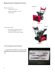
Medium Frame 2 & 3 Stage Snow Throwers Electric Chute Control Starting in 2012, an electric 4-way chute control system is available for some snow thrower models. There are two versions of the system: • Electric chute control with heated hand grips • Electric chute control without heated hand grips Both systems have two motors, one for pitch and the other for chute rotation. Both systems also have a module that supplies power to the electric motors.
Discharge Chute and Controls (Electric) Electric Joystick and Harness To remove/replace an electric joystick and harness: NOTE: The joystick is soldered into the harness. If the joystick needs to be replaced, the whole harness must be replaced. Ground lead 1. Remove the screw that holds the harness ground lead to the engine using a 10 mm wrench. See Figure 11.31. NOTE: On some models, the ground wire is attached to the engine next to the starter. 2. Disconnect the Alternator Connection. 3.
Medium Frame 2 & 3 Stage Snow Throwers 9. Remove the nut that is holding the joystick in place. See Figure 11.34. 10. Gently remove the joystick from the Joystick Bracket. 11. Install the joystick and harness by following the previous step in reverse order. NOTE: Make sure the harness grommet is seated in the Joystick Bracket. 12. Test run the unit in a safe area before returning it to service. Figure 11.34 Electric Joystick Bracket To remove/replace the joystick bracket: 1.
Discharge Chute and Controls (Electric) 6. Remove the right hand grip. NOTE: Unit without Heated Hand Grips can skip to step 7. 6a. Remove the two screws that hold the hand grip in place using a #2 Phillips screwdriver. See Figure 11.37. 6b. Slide the grip off of the handle. Figure 11.37 7. Loosen the screws that hold the right Cable Guide Pulley to the bracket enough to slip the cable off of the pulley. See Figure 11.38. 8. Disconnect the Drive Cable from the Control Lever. 9.
Medium Frame 2 & 3 Stage Snow Throwers 10. Loosen, but do not remove, the two screws that hold the control panel to the right handle bar. Figure 11.40 Shoulder Nut 11. Shoulder Bolt While holding the Cam Lock’s shoulder nut with a 1/ 2” wrench, remove the shoulder bolt with a 3/4” wrench. See Figure 11.41. Figure 11.41 12. Gently pry the Cam Lock’s tab out of the Control Lever. See Figure 11.42. Cam Lock’s Tab Figure 11.
Discharge Chute and Controls (Electric) 13. Slip the Control Lever and Torsion Spring out of the machine. See Figure 11.43. Figure 11.43 14. Remove the two screws that are holding the Joystick Bracket to the handle bar with a #2 Phillips screwdriver. See Figure 11.44. 15. Install the bracket by following the previous steps in reverse order. 16. Test run the unit in a safe area before returning it to service. Figure 11.
Medium Frame 2 & 3 Stage Snow Throwers Chute Control Assembly To remove/replace the Chute Control Assembly: 1. Remove the hair pin clip that secures the shaft to the Remote Head. NOTE: The shaft has an offset so that it can be used to manually rotate the chute. 2. Slide the shaft forward until it clears the Chute Control Assembly’s Coupler. See Figure 11.45. 3. Remove the shaft. 4.
Discharge Chute and Controls (Electric) Chute Control Motors To remove/replace a Chute Control Motor: 1. Remove the Chute Control Assembly by following the procedures described in the previous section of this chapter. 2. Remove the screws, indicated by the arrows in Figure 11.48, using a #2 Phillips screwdriver. 3. Depress the five tabs, indicated by the arrows in Figure 11.49, while separating the two housing halves. Figure 11.48 Figure 11.49 Grommet NOTE: For the Pitch Motor, skip to step 7. 4.
Medium Frame 2 & 3 Stage Snow Throwers 6. Slide the coupler off of the motor. Figure 11.51 7. Remove the Chute Pitch Adapter. See Figure 11.52. NOTE: The pitch adapter may have fallen off when the housings where separated. Chute Pitch Adapter Figure 11.52 8. Turn the housing over. 9. Remove the screw, indicated by the arrow in Figure 11.53, with a 5/16” wrench. 10. Slide the motor out of the housing. Figure 11.
Discharge Chute and Controls (Electric) Chute Pitch Adapter 11. Install the motors by following the previous steps in reverse order. NOTE: Make sure the Chute Pitch Adapter engages the Cable Guide as the housings are brought together. See Figure 11.54. NOTE: Tighten the screw that was removed in step 9 to a torque of 15 - 25 in lbs (2 - 3 Nm). Cable Guide Figure 11.54 NOTE: Make sure the Rotation Motor Harness Grommet is seated in the notch in the housings.
Medium Frame 2 & 3 Stage Snow Throwers Electric Chute Control Pitch Cables To remove/replace the Pitch Cables: 1. Remove the Chute Control Assembly by following the procedures described in the Chute Control Assembly section of this chapter. 2. Remove the screws, indicated by the arrows in Figure 11.56, using a #2 Phillips screwdriver. Figure 11.56 3. Depress the five tabs, indicated by the arrows in Figure 11.57, while separating the two housing halves. Figure 11.57 4.
Discharge Chute and Controls (Electric) Cable Guide 5. Disconnect the cables from the Cable Guide. See Figure 11.59. 6. Squeeze in the barbs on the Cable Jacket End, while pulling the cable out of the housing. See Figure 11.60. 7. Install the cables by following the previous steps in reverse order. Figure 11.59 Figure 11.60 Chute Pitch Adapter NOTE: Forward movement of joystick should result in the Chute Deflector moving down.
Medium Frame 2 & 3 Stage Snow Throwers NOTE: Make sure the Rotation Motor Harness Grommet is seated in the notch in the housings. NOTE: Make sure both motor harnesses are routed to the rear of the assembly as the housings are brought together. See Figure 11.55. NOTE: Tighten the three housing screws to a torque of 10 - 20 in lbs (1 - 2 Nm). 8. Install the Chute Control Assembly by following the procedures described in the Chute Control Assembly section of this chapter. 9.
Discharge Chute and Controls (Electric) Schematics Up, down, right and left refers to chute direction, which corresponds to back, forward, right and left respectively on the joystick.
Medium Frame 2 & 3 Stage Snow Throwers 144
MTD Products Inc - Product Training and Education Department FORM NUMBER - 769-09302 09/2013