Safe Operation Practices • Set-Up • Operation • Maintenance • Service • Troubleshooting • Warranty Operator’s Manual 4 x 4 Utility Vehicle - Models M465 & M467 WARNING READ AND FOLLOW ALL SAFETY RULES AND INSTRUCTIONS IN THIS MANUAL BEFORE ATTEMPTING TO OPERATE THIS MACHINE. FAILURE TO COMPLY WITH THESE INSTRUCTIONS MAY RESULT IN PERSONAL INJURY. CUB CADET LLC, P.O. BOX 361131 CLEVELAND, OHIO 44136-0019 Printed In USA Form No.
1 To The Owner Thank You Thank you for purchasing a Utility Vehicle manufactured by Cub Cadet LLC. It was carefully engineered to provide excellent performance when properly operated and maintained. Please read this entire manual prior to operating the equipment. It instructs you how to safely and easily set up, operate and maintain your machine. Please be sure that you, and any other persons who will operate the machine, carefully follow the recommended safety practices at all times.
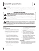
2 Important Safe Operation Practices WARNING: This symbol points out important safety instructions which, if not followed, could endanger the personal safety and/or property of yourself and others. Read and follow all instructions in this manual before attempting to operate this machine. Failure to comply with these instructions may result in personal injury. When you see this symbol.
Never leave vehicle unattended with the key in the ignition. Always turn key to the “Stop” position, set the parking brake and remove key. 21. Check overhead clearances carefully before driving under low hanging tree branches, wires, power lines, bridges, before entering or leaving buildings, or in any other situation where the operator and/or operator protective structure (OPS) may be struck, which could result in serious injury. 22.
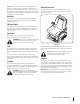
2. Travel slowly while on a slope. Always keep the forward speed limited when going down slopes to take advantage of the motor braking action. Cargo Box Lift 1. Stop vehicle on level ground and set Parking Brake before raising cargo box. 3. Keep all movement on the slopes slow and gradual. Avoid starting or stopping on a slope. 2. 4. Avoid slopes with slippery, loose, or bumpy surfaces as they are especially hazardous. On manual lift units, unload cargo box before raising cargo box. 3.
2. 3. e. Use extreme care while approaching blind corners, doorways, shrubs, trees or other objects that may block your vision of a child who may run into the path of the vehicle. 12. Use proper containers when draining fluids. Do not use food or beverage containers that may mislead someone into drinking from them. Properly dispose of the containers immediately following the draining of fluids. f. Remove key when vehicle is unattended to prevent unauthorized operation. 13.
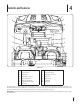
4 Controls and Features F A G B H I C J D K E L M N O Figure 4-1 A Check Engine Light I 12 Volt Power Outlet B Ignition Switch J Accelerator Pedal C Brake Pedal K Adjustable Seat Lever D Differential Lock Lever L Shift Lever E Parking Brake Lever M Cup Holders F Warning Light Cluster N Seat Belts G Engine Over-Temp Light O Fuel Tank H 4x4 Switch Read this operator’s manual, safety labels, and operating instructions on the vehicle before operating.
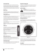
Accelerator Pedal Engine Over-Temp Light The accelerator pedal is located on the right side of the floor beneath the dash panel. Depressing the accelerator pedal will move the vehicle in the direction selected on the gearshift. As the pedal is depressed, speed will increase to the maximum selected range. Releasing the pedal reduces the speed, but does not stop the vehicle. The brake must be applied to stop vehicle. See Fig. 4-1.
NOTE: Every 50 hours a “change oil” message will flash on the display for 2 minutes every time the tractor is started. This message will repeat for the first two after each 50 hour interval. The oil pressure indicator light will also flash when this display is active. Before the interval expires, change the crankcase oil level as instructed in the Engine Manual.
5 Operation Filling Fuel Tank Stopping Engine 1. Stop vehicle on a level surface and apply parking brake. 1. 2. Turn the ignition key to the STOP position and remove the key. To stop utility vehicle, release accelerator pedal and depress brake pedal until vehicle comes to a complete stop. 3. Allow engine to cool several minutes before you add fuel. 2. Put unit back into Neutral. 4. Clean area around fuel cap and remove cap. 3. Lock parking brake and turn key switch to STOP position. 5.
Engaging 4x4 Electric Lift (Optional) The 4x4 switch is located on the right side of the dash panel. See the Controls & Features section. 1. Park the vehicle safely and turn key to the RUN position. 2. Raise cargo box by pressing and holding top of electric lift switch. Release switch when box is at desired dump height or when maximum height is reached. 1. To engage, stop or slow vehicle speed and push up on the switch. All four wheels will now continue to have power.
Towing Loads WARNING: To help prevent personal injury due to loss of control or tipping, always tow a load slowly enough to maintain control. 1. 2. Do not tow a load that exceeds 1,400 lbs. rolling weight (i.e. trailer plus cargo) and never exceed 140 lbs. tongue weight. Go slow when towing a heavy load. Allow for increased braking distance. Tow load at a speed slow enough to maintain control. This utility vehicle is equipped with a Operator Protection Structure (OPS) and seat belts.
6 Maintenance & Adjustments Engine Read the Kohler engine operator’s manual for any service or maintenance information pertaining to the engine. Engine Coolant Checking Engine Coolant Level Before each use, the engine coolant level in the overflow reservoir should be checked to ensure it is within the operating range. Engine coolant absorbs heat from the engine and transfers the heat to the air flowing through the radiator.
WARNING: Coolant is a toxic substance. Dispose in 4. an environmentally safe manner. Contact your area EPA office for proper disposal methods and recycling center locations. 7. Reinstall the drain plug and turn clockwise until fully tightened. 8. Turn the radiator cap counterclockwise to the first stop, then push downward on the cap and turn counterclockwise to remove. 9. In stages, SLOWLY pour the coolant solution into the filler neck, allowing as much air as possible to escape through the neck.
Battery 1. WARNING: The battery produces a flammable and Connect positive (+) jumper cable to booster battery positive (+) post (A). See Fig. 6-3. explosive gas. Do not smoke near battery. Wear eye protection and gloves when handling the battery. Do not allow direct metal contact across battery posts. The battery is sealed and is maintenance free. Acid levels cannot be checked and fluid can not be added.
Tire Pressure CV Boots WARNING: Explosive separation of tire and rim parts is possible when they are serviced incorrectly. Do not stand in front or over tire assembly when inflating. The recommended operating tire pressure is approximately 14-18 psi for all tires. Overinflating above recommended tire pressure can reduce the life of the tire. Check tire pressure before driving the vehicle.
Rear Knuckles Draining CVT Cover Lubricate two grease fittings on each axle with 2 or 3 shots of grease every 50 hours or after each use if consistently running unit in water deeper than axle. See Fig. 6-6. Drain CVT cover every 50 hours or after driving vehicle through more than 12” of water. 1. Remove CVT cover drain plug. See Fig. 6-7. Lube Figure 6-6 Figure 6-7 2. Allow water to completely drain out. 3. Reinstall drain plug, and tighten securely.
7 Service Headlight Bulbs Fuses 1. Raise hood to get access to the headlight assembly. 1. 2. Turn the bulb/socket assembly approximately a quarter turn counterclockwise to align its tabs with the notches of the reflector, then remove from the reflector. See Fig. 7-1. Unlatch and lift hood forward to get access to under the dash panel. 2. Remove fuse holder cover. See Fig. 7-2. Figure 7-2 Figure 7-1 3. Unplug the wire harness from the bulb/socket assembly. 4.
Wheels Changing Brake Pads WARNING: Using an unstable lifting device and WARNING: Using an unstable lifting device and vehicle support may result in bodily injury. Use a safe lifting device and supports to work on raised vehicle. vehicle support may result in bodily injury. Use a safe lifting device and supports to work on raised vehicle. 1. Stop the vehicle on a level surface and apply parking brake. 2. Turn the ignition key to the STOP position and remove the key.
8 Maintenance Chart Maintenance Schedule Before Each Use First 10 Hours Every 50 Hours P Check Transfer Case Oil P Change Transfer Case Oil* P Tighten Wheel Bolts Check Engine Coolant Level Every 100 Every 500 Hrs. or Yearly Hrs. or 2 Yrs. P P Change Engine Coolant P Inspect Cooling System Hoses Lubricate Rear Knuckles † P P P P Inspect OPS Inspect Front and Rear Shocks Inspect Ball Joints Inspect CV Boots Drain CVT Cover †† P P P * Change at the first 50 hours, then again at 500 hours.
Accessories 9 NOTE: For parts or accessories, contact your local Cub Cadet dealer. To locate the dealer nearest you call 877-282-8684 or log onto www.cubcadet.com.
10 Specifications NOTE: Specifications subject to change without notice. Engine/Electrical Dimensions Make 31HP* Kohler® Aegis EFI Length/ Width 119” x 63.5” Type/ Cylinders 4 Cycle Gas/ 3 Cylinders Tread Center F: 52”/ R: 50” Displacement 748cc Height (Overall) 78” Maximum Torque 45.4 ft. lb. @ 2400 RPM Wheelbase 78” Ignition Mechanically Controlled 1,650 lbs.
11 Troubleshooting Problem Engine will not start Cause(s) 1. Battery has low voltage. 2. Loose or corroded battery connections. 3. Fuse is blown. 4. Spark plug wire is loose or disconnected. 5. Faulty spark plug or coil. 6. No Fuel or improper fuel. 7. Plugged fuel filter. 8. Defective starter solenoid. 9. Open-circuit in wiring. Engine is difficult to start 1. Engine is cold. 2. Plugged fuel filter. 3. Carburetor not adjusted properly or dirty. 4. Engine oil viscosity too heavy. 5.
Problem Engine overheats Cause(s) 1. Air cleaner element missing or plugged. 2. Carburetor air intake tube plugged. 3. Engine oil low. 4. Engine operated too long at slow engine speed. Engine knocks 1. Low engine speed. 2. Stale or low octane fuel. 3. Engine overloaded. Engine loses power 1. Engine overheating. 2. Too much oil in engine. 3. Faulty spark plug. 4. Fuel supply being restricted. 5. Fuel filter plugged. 6. Fuel line pinched or kinked. 7. Fuel pump output not adjusted to specification. 8.
Problem Battery will not take a charge Cause(s) 1. Dead battery. 2. Loose or corroded connections. 3. Sulfated or worn-out battery. 4. Fluid level low. Difficult to shift Gears not lined up. Flip throttle and let it return to idle. If still hard to shift, contact your nearest Cub Cadet dealer.
FEDERAL and CALIFORNIA EMISSION CONTROL WARRANTY STATEMENT YOUR WARRANTY RIGHTS AND OBLIGATIONS The California Air Resources Board, the United States Environmental Protection Agency, and MTD Consumer Group Inc are pleased to explain the evaporative emission control system warranty on your 2008 off-road engine and equipment.
WARRANTED PARTS: The repair or replacement of any warranted part otherwise eligible for warranty coverage may be excluded from such warranty coverage if MTD Consumer Group Inc demonstrates that the off-road engine and equipment has been abused, neglected, or improperly maintained, and that such abuse, neglect, or improper maintenance was the direct cause of the need for repair or replacement of the part.
CUB CADET LLC MANUFACTURER’S LIMITED WARRANTY FOR utility vehicles The limited warranty set forth below is given by Cub Cadet LLC with respect to new merchandise purchased and used in the United States, its possessions and territories, and by MTD Products Limited with respect to new merchandise purchased and used in Canada and/or its territories and possessions.