Operator’s Manual SERIES 1000 Hydrostatic Lawn Tractor Models LT1042 LT1045 LT1046 LT1050 IMPORTANT: READ SAFETY RULES AND INSTRUCTIONS CAREFULLY Warning: This unit is equipped with an internal combustion engine and should not be used on or near any unimproved forest-covered, brush-covered or grass-covered land unless the engine’s exhaust system is equipped with a spark arrester meeting applicable local or state laws (if any).
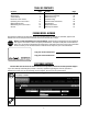
TABLE OF CONTENTS Content Important Safe Operation Practices Slope Gauge Tractor Set-up Know Your Lawn Tractor Operating Your Lawn Tractor Making Adjustments Maintaining Your Lawn Tractor Service Page 3 7 8 9 12 17 19 25 Content Off-season Storage Maintenance Schedule Maintenance Log Troubleshooting Attachments & Accessories Specifications Replacement Parts Warranty Information Page 30 30 31 32 33 35 34 37 FINDING MODEL NUMBER This Operator’s Manual is an important part of your new lawn tractor.
SECTION 1: IMPORTANT SAFE OPERATION PRACTICES WARNING: This symbol points out important safety instructions which, if not followed, could endanger the personal safety and/or property of yourself and others. Read and follow all instructions in this manual before attempting to operate this machine. Failure to comply with these instructions may result in personal injury. When you see this symbol—heed its warning.
23. Muffler and engine become hot and can cause a burn. Do not touch. 24. Check overhead clearances carefully before driving under low hanging tree branches, wires, door openings etc., where the operator may be struck or pulled from the unit, which could result in serious injury. 25. Disengage all attachment clutches, depress the brake pedal completely and shift into neutral before attempting to start engine. 26. Your machine is designed to cut normal residential grass of a height no more than 10”.
e. Use extreme care when approaching blind corners, doorways, shrubs, trees or other objects that may block your vision of a child who may run into the machine. f. To avoid back-over accidents, always disengage the cutting blade(s) before shifting into reverse. The “Reverse Caution Mode” should not be used when children or others are around. g. Keep children away from hot or running engines. They can suffer burns from a hot muffler. h. Remove key when machine is unattended to prevent unauthorized operation.
8. Never tamper with the safety interlock system or other safety devices. Check their proper operation regularly. 9. After striking a foreign object, stop the engine, disconnect the spark plug wire(s) and ground against the engine. Thoroughly inspect the machine for any damage. Repair the damage before starting and operating. 10. Never attempt to make adjustments or repairs to the machine while the engine is running. 11.
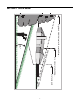
SECTION 2: SLOPE GAUGE OR A CORNER OF A BUILDING OR A FENCE POST PE S A SLO E RE P R E S ENT D LIN LO N G D OTTE &OLD A 3IGHT AND HOLD THIS LEVEL WITH A VERTICAL TREE 7
SECTION 3: TRACTOR SET-UP Gas and Oil Fill-up Shipping Brace Removal The gasoline tank is located under the fender and has a capacity of three and-a-half gallons. Unthread the fuel cap by turning it counterclockwise. Use only clean, fresh (under 30 days old), unleaded gasoline. Fill tank to no more than four inches below the top of the filler neck to allow space for fuel expansion. Do not overfill.
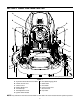
SECTION 4: KNOW YOUR LAWN TRACTOR A B G C + BATTERY PTO / BLADE ENGAGE OIL PRESSURE HOURS 1/10 H PARKING P BRAKE I J D K L E F M NOTE: Steering Wheel not shown for clarity.
Throttle Control Lever The throttle control lever is located on the left side of the tractor’s dash panel. This lever controls the speed of the engine. When set in a given position, the throttle will maintain a uniform engine speed. Ignition Switch Module Fast Position WARNING: Never leave a running machine unattended. Always disengage PTO, move shift lever into neutral position, set parking brake, stop engine and remove key to prevent unintended starting.
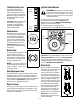
Systems Indicator Monitor / Hour Meter Electric PTO / Blade Engage Knob To engage the power to the cutting deck or other (separately available) attachments, pull outward on the PTO/Blade Engage knob. Push the PTO/ Blade Engage knob inward to disengage the power to the cutting deck or other (separately available) attachments. 42.0 NOTE: The PTO/Blade Engage knob must be in the disengaged (OFF) position when starting the engine.
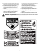
SECTION 5: OPERATING YOUR LAWN TRACTOR WARNING: Use extreme caution while WARNING operating the tractor in the REVERSE CAUTION MODE. Always look down and behind before and while backing. Do not operate the tractor when children or others are around. Stop the tractor immediately if someone enters the area. AVOID SERIOUS INJURY OR DEATH • • • • • • • • • • • • GO UP AND DOWN SLOPES, NOT ACROSS. AVOID SUDDEN TURNS. DO NOT OPERATE THE UNIT WHERE IT COULD SLIP OR TIP.
Setting the Gauge Wheels • If the gauge wheels have excessive clearance with the surface below, lower the wheels to the index hole that provides the approximate 1/2" clearance as described above. Refer to Leveling the Deck on page 17 of this manual for more detailed instructions regarding various deck adjustments. Select the height position of the cutting deck by placing the deck lift lever in any of the six different cutting height notches on the right fender.
Engaging the Parking Brake • To engage the parking brake: • Fully depress the brake pedal and hold it while gently pushing the parking brake lever downward. • Hold the parking brake lever down while removing your foot from the brake pedal. • Once engaged, the parking brake lever and the brake pedal will lock in the “down” position. To disengage the parking brake: • IMPORTANT: Do NOT attempt to change the direction of travel when the tractor is in motion.
• Depress the brake pedal to disengage the cruise control and stop the tractor. • Lightly depress the drive pedal. To change the direction of travel to reverse when operating with cruise control, depress the brake pedal to disengage the cruise control and bring the tractor to a complete stop. Then slowly depress the rear portion of the drive pedal with the ball of your foot to travel in reverse.
• • • • • • For best results it is recommended that the first two laps be cut with the discharge thrown towards the center. After the first two laps, reverse the direction to throw the discharge to the outside for the balance of cutting. This will give a better appearance to the lawn. Do not cut the grass too short. Short grass invites weed growth and yellows quickly in dry weather. Mowing should always be done with the engine at full throttle.
SECTION 6: MAKING ADJUSTMENTS WARNING: Never attempt to make any • adjustments while the engine is running, except where specified in the operator’s manual. • Leveling the Deck Tighten the inner hex nuts front against the front hanger bracket to raise the front of the deck; loosen the hex nuts to lower the front of the deck. See Figure 10. Retighten the two lock nuts against the inner hex nuts when proper adjustment is achieved.
Parking Brake Adjustment WARNING: Never attempt to adjust the brakes while the engine is running. Always disengage PTO, stop engine and remove key to prevent unintended starting. If the tractor does not come to a complete stop when the brake pedal is completely depressed, or if the tractor’s rear wheels can roll with the parking brake applied, the brake is in need of adjustment. The brake disc can be found on the right side of the transmission in the rear of the tractor. Adjust if necessary as follows.
SECTION 7: MAINTAINING YOUR LAWN TRACTOR NOTE: Refer to Maintenance Chart on page 30 for a TEMPERATURE / OIL VISCOSITY CHART reference of recommended maintenance intervals. WARNING: Before performing any maintenance or repairs, disengage PTO, set parking brake, stop engine and remove key to prevent unintended starting.
IMPORTANT: The engine may overheat and/or damage may result if the oil level is below the ADD or over the FULL on the dipstick. • Oil Fill Cap / Dipstick Reinstall the oil fill cap/dipstick securely onto the oil fill tube. IMPORTANT: The oil fill cap/dipstick must be installed securely onto the tube at all times when the engine is operating. Severe engine damage could result from failure to do so.
• • Service Paper Element Slowly pour oil into the fill tube. Fill the crankcase until the oil level reaches the full (F) mark on the dipstick (Refer to Figure 14 on Page 19). Reinstall the oil fill cap/dipstick securely into the oil fill tube. The paper element should be replaced at least every 100 hours of operation. Replace more frequently if the tractor is operated under extremely dusty conditions.
• Check the gap using a feeler gauge and adjust, if necessary, by carefully bending the ground electrode. See Figure 15. Set the spark plug gap to .76 mm (0.030 in.). 1. Drive the tractor to a level, clear spot on your lawn, near enough for your garden hose to reach. IMPORTANT: Make certain the tractor’s discharge chute is directed AWAY from your house, garage, parked cars, etc. Feeler Gauge 2. Disengage the PTO (Blade Engage), set the parking brake and stop the engine. 3.
Lubrication Carburetor WARNING: Before lubricating, repairing, or NOTE: Carburetor adjustments should be made only inspecting, always disengage PTO, set parking brake, stop engine and remove key to prevent unintended starting. after the engine has warmed up. The engines on Cub Cadet Series 1000 tractors are equipped with a fixed main jet carburetor. Engine Carburetors are equipped with a idle speed adjustment screw and a low idle fuel mixture screw.
• Make sure fuel is reaching the carburetor. Check the fuel lines and fuel pump for restrictions or faulty components, replace as necessary. • Make sure the air cleaner element is clean and all air cleaner element components are secure. If, after checking the items listed above, the engine is hard to start, runs roughly, or stalls at low idle speed, it may be necessary to adjust or service the carburetor. 3. Low Idle Speed Setting: Place the throttle control into the “idle” or “slow” position.
SECTION 8: SERVICE Tires • WARNING: Never exceed the maximum inflation pressure shown on the sidewall of the tire. Place a block of wood between the center deck housing baffle and the cutting blade to act as a stabilizer. See Figure 20. Hex Flange Nut Wood Block The recommended operating tire pressure is approximately 10 psi for the rear tires and 14 psi for the front tires. Refer to the tire sidewall for exact tire manufacturer’s recommended or maximum psi. Do not overinflate.
Battery Cutting Deck Removal The battery is sealed and is maintenance-free. Acid levels cannot be checked and fluid can not be added. To remove the cutting deck, proceed as follows: • Place the PTO/Blade Engage knob in the disengaged (OFF) position and engage the parking brake. • Lower the deck by moving the deck lift lever into the bottom notch on the right fender. • Remove the deck belt from around the tractor’s electric PTO clutch (refer to Changing the Deck Belt).
Hydrostatic Transmission Changing the Deck Belt Keep the area around the transmission cooling fan free of grass and debris at all times. The hydrostatic transmission is sealed at the factory and is maintenance free. The fluid level cannot be checked and on most models, cannot be changed. WARNING: Be sure to shut the engine off, remove ignition key, disconnect the spark plug wire(s) and ground against the engine to prevent unintended starting before removing the belt(s).
46-inch Decks 50-inch Decks • • Carefully grasp the idler pulley and pivot it toward the tractor’s left side to relieve tension on the belt. See Figure 24. To ease in removing the belt in later steps, loosen, but do not remove, the bolt which secures the pivoting idler pulley to the idler bracket. See Figure 25.
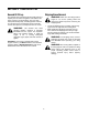
LT1042 LT1045 & LT1046 LT1050 29
SECTION 9: OFF-SEASON STORAGE Clean and lubricate the tractor as instructed in Section 7: MAINTAINING YOUR LAWN TRACTOR on page 19 of this manual before storing for an extended period. To empty the system, run the engine until the tank and system are empty. WARNING: Allow engine to cool. Extinguish cigarettes, cigars, pipes, and other sources of ignition prior to draining fuel. Drain fuel only into an approved container outdoors, away from an open flame.
SECTION 11: MAINTENANCE LOG Please keep a record of the maintenance performed on your tractor.
SECTION 12: TROUBLESHOOTING Trouble Possible Cause(s) Corrective Action Engine fails to start PTO/Blade Engage knob engaged. Parking brake not engaged. Spark plug wire(s) disconnected. Throttle control lever not in correct starting position. Choke not activated Fuel tank empty, or stale fuel. Blocked fuel line. Faulty spark plug. Engine flooded. Unit running with CHOKE activated. Spark plug wire(s) loose. Blocked fuel line or stale fuel. Place knob in disengaged (OFF) position. Engage parking brake.
SECTION 13: ATTACHMENTS & ACCESSORIES The following attachments and accessories are compatible for Series 1000 Lawn Tractors. See your Cub Cadet dealer or the retailer from which you purchased your tractor for information regarding price and availability. NOTE: Cub Cadet Series 1000 lawn tractors are NOT designed for use with any type of ground-engaging attachments (e.g. tiller or mulboard plow). Use of this type of equipment WILL void the tractor’s warranty.
SECTION 14: REPLACEMENT PARTS NOTE: Download a complete Cub Cadet Series 1000 Parts Manual free of charge at www.cubcadet.com or phone (800) 800-7310 to purchase a Parts Manual (Form No. 769-10578F). Champion Spark Plug(s) Kohler Air Filter (Paper Element) Kohler Air Filter (Precleaner) Kohler Oil Filter Kohler Fuel Filter Drive Belt (Transmission) Drive Belt (Mowing Deck) Deck Blades LT1042 RC12YC 20-083-02-S 20-083-03-S 52-050-02-S 25-050-22-S 754-0461 754-04060B 742-04126 (Qty.
SECTION 15: SPECIFICATIONS* LT1042 LT1045 LT1046 LT1050 Capacities Fuel Tank 13.2 liters (3.5 gallons) 13.2 liters (3.5 gallons) 13.2 liters (3.5 gallons) 13.2 liters (3.5 gallons) Engine Crankcase (w/ filter) 1.5 liters (50.75 oz.) 1.5 liters (50.75 oz.) 1.7 liters (57.5 oz.) 1.7 liters (57.5 oz.) Transmission 2.25 liters (76 oz.) 2.25 liters (76 oz.) 2.25 liters (76 oz.) 2.25 liters (76 oz.
CALIFORNIA EMISSION CONTROL WARRANTY STATEMENT YOUR WARRANTY RIGHTS AND OBLIGATIONS The California Air Resources Board and Cub Cadet LLC are pleased to explain the evaporative emission control system warranty on your 2006 lawn mower. In California, new lawn mower must be designed, built and equipped to meet the State’s stringent anti-smog standards.
KOHLER CO. FEDERAL AND CALIFORNIA EMISSION CONTROL SYSTEMS LIMITED WARRANTY UTILITY AND LAWN AND GARDEN ENGINES The U.S. Environmental Protection Agency (EPA), the California Air Resources Board (CARB), and Kohler Co. are pleased to explain the Federal and California Emission Control Systems Warranty on your small off-road equipment engine. For California, engines produced in 1995 and later must be designed, built and equipped to meet the state’s stringent anti-smog standards.
CUB CADET LLC MANUFACTURER’S LIMITED WARRANTY FOR SERIES 1000 & SERIES 1500 TRACTORS IMPORTANT: To obtain warranty coverage owner must present an original proof of purchase and applicable maintenance records to the servicing dealer. Please see the operator’s manual for information on required maintenance and service intervals.
CUB CADET LLC, P.O.