Operator’s Manual SERIES 1000 CVT Lawn Tractor Model LT1040 IMPORTANT: READ SAFETY RULES AND INSTRUCTIONS CAREFULLY Warning: This unit is equipped with an internal combustion engine and should not be used on or near any unimproved forest-covered, brush-covered or grass-covered land unless the engine’s exhaust system is equipped with a spark arrester meeting applicable local or state laws (if any). If a spark arrester is used, it should be maintained in effective working order by the operator.
TABLE OF CONTENTS Content Important Safe Operation Practices Slope Gauge Tractor Set-up Know Your Lawn Tractor Operating Your Lawn Tractor Making Adjustments Maintaining Your Lawn Tractor Service Page 3 7 8 9 12 17 19 24 Content Off-season Storage Maintenance Schedule Maintenance Log Troubleshooting Attachments & Accessories Specifications Replacement Parts Warranty Information Page 27 27 28 29 30 32 31 34 FINDING MODEL NUMBER This Operator’s Manual is an important part of your new lawn tractor.
SECTION 1: IMPORTANT SAFE OPERATION PRACTICES WARNING: This symbol points out important safety instructions which, if not followed, could endanger the personal safety and/or property of yourself and others. Read and follow all instructions in this manual before attempting to operate this machine. Failure to comply with these instructions may result in personal injury. When you see this symbol—heed its warning.
. Follow the manufacturer’s recommendations for wheel weights or counterweights to improve stability. 5. Use extra care with grass catchers or other attachments. These can change the stability of the machine. 6. Keep all movement on the slopes slow and gradual. Do not make sudden changes in speed or direction. Rapid engagement or braking could cause the front of the machine to lift and rapidly flip over backwards which could cause serious injury. 7. Avoid starting or stopping on a slope.
e. Extinguish all cigarettes, cigars, pipes and other sources of ignition. f. Never fuel machine indoors. g. Never remove gas cap or add fuel while the engine is hot or running. Allow engine to cool at least two minutes before refueling. h. Never over fill fuel tank. Fill tank to no more than ½ inch below bottom of filler neck to allow space for fuel expansion. i. Replace gasoline cap and tighten securely. j. If gasoline is spilled, wipe it off the engine and equipment. Move unit to another area.
For safety protection, frequently check components and replace immediately with original equipment manufacturer’s (O.E.M.) parts only, listed in this manual. “Use of parts which do not meet the original equipment specifications may lead to improper performance and compromise safety!” 12. Do not change the engine governor settings or overspeed the engine. The governor controls the maximum safe operating speed of the engine. 13. Maintain or replace safety and instruction labels, as necessary. 14.
SECTION 2: SLOPE GAUGE OR A CORNER OF A BUILDING OR A FENCE POST PE S A SLO E RE P R E S ENT D LIN O N G D OTTE L &OLD A 3IGHT AND HOLD THIS LEVEL WITH A VERTICAL TREE 7
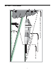
SECTION 3: TRACTOR SET-UP Gas and Oil Fill-up Shipping Brace Removal The gasoline tank is located under the fender and has a capacity of three gallons. Remove the fuel cap by turning it counterclockwise. Use only clean, fresh (under 30 days old), unleaded gasoline. Fill tank to no more than four inches below the top of the filler neck to allow space for fuel expansion. Do not overfill.
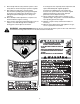
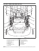
SECTION 4: KNOW YOUR LAWN TRACTOR A H B I C J K D L E M F G NOTE: Steering Wheel not shown for clarity. Figure 2 A B C D E F G Systems Indicator Monitor/Hour Meter Throttle Control Lever Choke Control Parking Brake Lever Shift Lever Seat Adjustment Lever Cup Holder H I J K L M Ignition Switch Module PTO (Blade Engage) Knob Brake Pedal Drive Pedal Cruise Control Lever Deck Lift Lever NOTE: Any reference in this manual to the RIGHT or LEFT side of the tractor is observed from operator’s position.
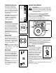
Throttle Control Lever The throttle control lever is located on the left side of the tractor’s dash panel. This lever controls the speed of the engine. When set in a given position, the throttle will maintain a uniform engine speed. Ignition Switch Module Fast Position WARNING: Never leave a running machine unattended. Always disengage PTO, move shift lever into neutral position, set parking brake, stop engine and remove key to prevent unintended starting.
Systems Indicator Monitor / Hour Meter Deck Lift Lever Found on your tractor’s right fender, the deck lift lever is used to change the height of the cutting deck. To use, move the lever to the left, then place in the notch best suited for your application. Electric PTO / Blade Engage Knob 42.0 To engage the power to the cutting deck or other (separately available) attachments, pull outward on the PTO/Blade Engage knob.
SECTION 5: OPERATING YOUR LAWN TRACTOR WARNING: Use extreme caution while operating the tractor in the REVERSE CAUTION MODE. Always look down and behind before and while backing. Do not operate the tractor when children or others are around. Stop the tractor immediately if someone enters the area. WARNING AVOID SERIOUS INJURY OR DEATH • • • • • • • • • • • • GO UP AND DOWN SLOPES, NOT ACROSS. AVOID SUDDEN TURNS. DO NOT OPERATE THE UNIT WHERE IT COULD SLIP OR TIP.
Setting the Gauge Wheels • If the gauge wheels have excessive clearance with the surface below, lower the wheels to the index hole that provides the approximate 1/2" clearance as described above. Refer to Leveling the Deck on page 17 of this manual for more detailed instructions regarding various deck adjustments. Select the height position of the cutting deck by placing the deck lift lever in any of the six different cutting height notches on the right fender.
Engaging the Parking Brake Driving On Slopes To engage the parking brake: Refer to the SLOPE GAUGE on page 7 to help determine slopes where you may operate the tractor safely. • Fully depress the brake pedal and hold it while gently pushing the parking brake lever downward. • Hold the parking brake lever down while removing your foot from the brake pedal. • Once engaged, the parking brake lever and the brake pedal will lock in the “down” position.
Using the Deck Lift Lever Mowing To raise the cutting deck, move the deck lift lever to the left, then place it in the notch best suited for your application. Refer to Setting The Cutting Height earlier in this section. WARNING: To help avoid blade contact or a thrown object injury, keep bystanders, helpers, children and pets at least 75 feet from the machine while it is in operation. Stop machine if anyone enters the area.
Mulching cutting deck without mulching, simply remove the mulch plug by unthreading the plastic wing nut which fastens it to the cutting deck. This will allow the clippings to discharge out the side. See Figure 7. Cub Cadet Series 1000 tractors are equipped with a mulch kit which incorporates special blades, already standard on your tractor, in a process of recirculating grass clippings repeatedly beneath the cutting deck.
SECTION 6: MAKING ADJUSTMENTS WARNING: Never attempt to make any • adjustments while the engine is running, except where specified in the operator’s manual. Side to Side Retighten the outer lock nut against the inner hex nut when proper adjustment is achieved. Leveling the Deck If the cutting deck appears to be mowing unevenly, a side to side adjustment can be performed. Adjust if necessary as follows: NOTE: Check the tractor’s tire pressure before • performing any deck leveling adjustments.
Parking Brake Adjustment If the tractor does not come to a complete stop when the brake pedal is completely depressed, or if the tractor’s rear wheels can roll with the parking brake applied (and the hydrostatic relief valve open), the brake is in need of adjustment. See your Cub Cadet dealer to have the brake properly adjusted.
SECTION 7: MAINTAINING YOUR LAWN TRACTOR NOTE: Refer to Maintenance Chart on page 27 for a TEMPERATURE / OIL VISCOSITY CHART reference of recommended maintenance intervals. WARNING: Before performing any maintenance or repairs, disengage PTO, set parking brake, stop engine and remove key to prevent unintended starting.
Changing the Engine OIl Changing the Oil Filter After draining the oil, proceed as follows: The engine oil and oil filter should be changed after every 50 hours of tractor operation. NOTE: Refer to the Replacement Parts table found on page 30 of this manual for the proper oil filter. WARNING: If the engine has been recently • run, the engine, muffler and surrounding metal surfaces will be hot and can cause burns to the skin.
Air Filter • The engine is equipped with a replaceable, high density paper air cleaner element and an oiled, foam precleaner. Always examine the air cleaner before starting the engine. Check for a buildup of dirt and debris around the air cleaner system. Keep this area clean. Also check for loose or damaged components. Replace all bent or damaged air cleaner components.
Fuel Filter 5. Turn the water on. 6. While sitting in the operator’s position on the tractor, start the engine and place the throttle lever in the FAST (rabbit) position. 7. Move the tractor’s PTO (Blade Engage) into the ON position. 8. Remain in the operator’s position with the cutting deck engaged for a minimum of two minutes, allowing the underside of the cutting deck to thoroughly rinse. 9. Move the tractor’s PTO (Blade Engage) into the OFF position. 10.
Deck Wheels Lean Each of the tractor deck’s front gauge wheels is equipped with a grease fitting. Lubricate with a No. 2 multi-purpose grease applied with a grease gun after every 25 hours of tractor operation. Adjust to Midpoint Carburetor NOTE: Carburetor adjustments should be made only after the engine has warmed up. The engines on Cub Cadet Series 1000 tractors are equipped with a fixed main jet carburetor.
SECTION 8: SERVICE Tires • WARNING: Never exceed the maximum inflation pressure shown on the sidewall of the tire. • The recommended operating tire pressure is approximately 10 psi for the rear tires and 14 psi for the front tires. Remove the deck from beneath the tractor (refer to Cutting Deck Removal on page 25), then gently flip the deck over to expose its underside. Place a block of wood between the center deck housing baffle and the cutting blade to act as a stabilizer. See Figure 17.
Battery IMPORTANT: When charging your tractor’s battery, use only a charger designed for 12V lead-acid batteries. Read your battery charger’s Owner’s Manual prior to charging your tractor’s battery. Always follow its instructions and heed its warnings. California Proposition 65 Warning: Battery posts, terminals, and related accessories contain lead and lead compounds, chemicals known to the State of California to cause cancer and reproductive harm. Wash hands after handling.
Changing The Transmission Drive Belt To change or replace the deck belt on your tractor, proceed as follows: NOTE: Several components must be removed and • special tools (i.e. air/impact wrench) used in order to change the tractor’s transmission drive belt. See your Cub Cadet dealer to have your drive belt replaced. • • Changing the Deck Belt WARNING: Be sure to shut the engine off, • • and remove the ignition key to prevent unintended starting before removing the belt.
SECTION 9: OFF-SEASON STORAGE Clean and lubricate the tractor as instructed in Section 7: MAINTAINING YOUR LAWN TRACTOR on page 19 of this manual before storing for an extended period. To empty the system, run the engine until the tank and system are empty. WARNING: Drain fuel only into an approved container outdoors, away from an open flame. Allow engine to cool. Extinguish cigarettes, cigars, pipes, and other sources of ignition prior to draining fuel.
SECTION 11: MAINTENANCE LOG Please keep a record of the maintenance performed on your tractor.
SECTION 12: TROUBLESHOOTING Trouble Possible Cause(s) Corrective Action Engine fails to start PTO/Blade Engage knob engaged. Parking brake not engaged. Spark plug wire(s) disconnected. Throttle control lever not in correct starting position. Choke not activated Fuel tank empty, or stale fuel. Blocked fuel line. Faulty spark plug. Engine flooded. Unit running with CHOKE activated. Spark plug wire(s) loose. Blocked fuel line or stale fuel. Place knob in disengaged (OFF) position. Engage parking brake.
SECTION 13: ATTACHMENTS & ACCESSORIES The following attachments and accessories are compatible for Series 1000 Lawn Tractors. See your Cub Cadet dealer or the retailer where you purchased your tractor for information regarding price and availability. NOTE: Cub Cadet Series 1000 lawn tractors are NOT designed for use with any type of ground-engaging attachments (e.g. tiller or moldboard plow). Use of this type of equipment WILL void the tractor’s warranty. LT1040 19A-102 16 cu. ft.
FA CT UIN TS EN E G SECTION 14: REPLACEMENT PARTS O R Y PA R NOTE: Phone (800) 965-4CUB to order replacement parts or a complete Parts Manual (have your full model number and serial number ready). Parts Manual downloads are also available free of charge at www.cubcadet.com.
SECTION 15: SPECIFICATIONS* LT1040 Capacities Fuel Tank 3.0 gal. (11.4 liters) Engine Crankcase (w/ filter) 50.75 oz. (1.5 liters) Continuously Variable Transmission Forward Speed 0 m.p.h. - 5.2 m.p.h. Reverse Speed 0 m.p.h. - 2.3 m.p.h. Engine (Air-cooled, 4-cycle) Make Kohler Courage Model SV540 Cylinders Single Bore 89 mm (3.50 in.) Stroke 86 mm (3.38 in.) Displacement 535 cc (32.6 cubic in.) Power @3600 RPM 18 HP (13.4 kW)** Maximum Torque 43.5 Nm (32.1 ft. lb.
CALIFORNIA EMISSION CONTROL WARRANTY STATEMENT YOUR WARRANTY RIGHTS AND OBLIGATIONS The California Air Resources Board and Cub Cadet LLC are pleased to explain the evaporative emission control system warranty on your 2007 lawn mower. In California, new lawn mower must be designed, built and equipped to meet the State’s stringent anti-smog standards.
KOHLER CO. FEDERAL AND CALIFORNIA EMISSION CONTROL SYSTEMS LIMITED WARRANTY UTILITY AND LAWN AND GARDEN ENGINES The U.S. Environmental Protection Agency (EPA), the California Air Resources Board (CARB), and Kohler Co. are pleased to explain the Federal and California Emission Control Systems Warranty on your small off-road equipment engine. For California, engines produced in 1995 and later must be designed, built and equipped to meet the state’s stringent anti-smog standards.
CUB CADET LLC MANUFACTURER’S LIMITED WARRANTY FOR SERIES 1000 & SERIES 1500 TRACTORS IMPORTANT: To obtain warranty coverage owner must present an original proof of purchase and applicable maintenance records to the servicing dealer. Please see the operator’s manual for information on required maintenance and service intervals.
CUB CADET LLC, P.O.