Operator’s Manual SERIES 1000 Hydrostatic Lawn Tractor Model LT1024 IMPORTANT: READ SAFETY RULES AND INSTRUCTIONS CAREFULLY Warning: This unit is equipped with an internal combustion engine and should not be used on or near any unimproved forest-covered, brushcovered or grass-covered land unless the engine’s exhaust system is equipped with a spark arrester meeting applicable local or state laws (if any). If a spark arrester is used, it should be maintained in effective working order by the operator.
TABLE OF CONTENTS Content Page Important Safe Operation Practices ............................................................................... 3 Slope Gauge .................................................................................................................. 7 Tractor Set-up ................................................................................................................ 8 Know Your Lawn Tractor ................................................................................
SECTION 1: IMPORTANT SAFE OPERATION PRACTICES WARNING: This symbol points out important safety instructions which, if not followed, could endanger the personal safety and/or property of yourself and others. Read and follow all instructions in this manual before attempting to operate this machine. Failure to comply with these instructions may result in personal injury. When you see this symbol—heed its warning.
unload properly. 23. Muffler and engine become hot and can cause a burn. Do not touch. 24. Check overhead clearances carefully before driving under low hanging tree branches, wires, door openings etc., where the operator may be struck or pulled from the unit, which could result in serious injury. 25. Disengage all attachment clutches, depress the brake pedal completely before attempting to start engine. 4. 5. 6. 26. Your machine is designed to cut normal residential grass of a height no more than 10”.
gasoline dispenser nozzle. d. Keep the nozzle in contact with the rim of the fuel tank or container opening at all times until fueling is complete. Do not use a nozzle lock-open device. e. Extinguish all cigarettes, cigars, pipes and other sources of ignition. f. Never fuel machine indoors. g. Never remove gas cap or add fuel while the engine is hot or running. Allow engine to cool at least two minutes before refueling. h. Never over fill fuel tank.
over-speed the engine. The governor controls the maximum safe operating speed of the engine. 12. Maintain or replace safety and instruction labels, as necessary. 13. Observe proper disposal laws and regulations for gas, oil, etc. to protect the environment. 14. Grass catcher components and the discharge cover are subject to wear and damage which could expose moving parts or allow objects to be thrown.
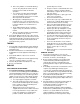
SLOPE GAUGE FO LD O ND OTT ED L I NE 15° NTIN G A 15 °S LO P E OR A FENCE POST A CORNER OF A BUILDING A POWER POLE SIGHT AND HOLD THIS LEVEL WITH A VERTICAL TREE , RE P RE SE WARNING Do not mow on inclines with a slope in excess of 15 degrees (a rise of approximately 2-1/2 feet every 10 feet). A riding mower could overturn and cause serious injury.
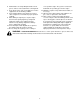
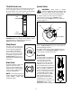
SAFETY LABELS TO REDUCE THE RISK OF INJURY, DO NOT OPERATE UNLESS DISCHARGE COVER OR GRASS CATCHER IS IN ITS PROPER PLACE. IF DAMAGED, REPLACE IMMEDIATELY. WARNING TO AVOID SERIOUS INJURY OR DEATH DANGER AVOID SE RIOUS INJURY OR DEATH • K EEP AND M S AND FEET AWAY FRO R O T A THI N G PARTS .40 THE • REMOV Y BLA DE INE OBJECTS THAT CAN BE THROWNLBASSES. ANY DIRECTION. WEAR SAFETY G • D O NOT O W W H E N C H IL D R E N O R O T H E R S A R E A R O U N D. .
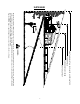
SECTION 3: KNOW YOUR LAWN TRACTOR A B G C H + BATTERY PTO / BLADE ENGAGE OIL PRESSURE HOURS 1/10 PARKING P BRAKE I J D K L E F M NOTE: Steering Wheel not shown for clarity.
Throttle Control Lever Ignition Switch The throttle control lever is located on the left side of the tractor’s dash panel. This lever controls the speed of the engine. When set in a given position, the throttle will maintain a uniform engine speed. See Figure 2. WARNING: Never leave a running machine unattended. Always disengage the PTO, set parking brake, stop engine and remove key to prevent unintended starting.
Hour Meter Electric PTO / Blade Engage Knob Located in the center of the tractor’s console, the hour meter operates whenever the engine is running and records the actual hours of tractor operation. See Figure 4. PTO To engage the power to the cutting deck or other (separately available) attachments, pull OFF ON outward on the PTO/Blade Engage knob. Push the PTO/ Blade Engage knob inward to disengage the power to the cutting deck.
Seat Adjustment Lever Deck Lift Lever To adjust the seat forward or backward, slide the seat adjustment lever to the left and reposition the seat to the desired position. Once a comfortable position is found, release the seat adjustment lever to lock the seat in place. Refer to Seat Adjustment on page 17 of this manual for more detailed instructions. Found on your tractor’s right fender, the deck lift lever is used to change the height of the cutting deck.
Stopping the Engine WARNING: If you strike a foreign object, stop the engine, disconnect the spark plug wire(s) and ground against the engine. Thoroughly inspect the machine for any damage. Repair the damage before restarting and operating Shoulder Screw Lock Nut • Shoulder Screw • • Lock Nut • If the blades are engaged, place the PTO/Blade Engage knob in the disengaged (OFF) position. Place the throttle control near the FAST position Turn the ignition key counterclockwise to the STOP position.
• Setting The Cruise Control To travel FORWARD, slowly depress the upper portion of the drive pedal forward until the desired speed is achieved. See Figure 6. NOTE: The cruise control feature should only be utilized while traveling in the forward direction. Brake Pedal • • • • Drive Pedal Slowly depress the upper portion of the drive pedal until the desired speed is achieved. Lightly depress the cruise control lever.
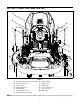
Moving The Tractor Manually • Top View Front View Your tractor’s transmission is equipped with a hydrostatic relief valve for occasions when it is necessary to move the tractor manually. Opening this valve permits the fluid in the transmission to bypass its normal route, allowing the rear tires to "freewheel." To open the hydrostatic relief valve, proceed as follows: PTO ON OFF OFF ON Locate the hydrostatic bypass rod in the rear of the tractor. See Figure 7.
SECTION 5: MAKING ADJUSTMENTS WARNING: Never attempt to make any • adjustments while the engine is running, except where specified in the operator’s manual. • Leveling the Deck Locate the two lock nuts on the opposite side of the stabilizer bracket. See Figure 9. Tighten the lock nuts to raise the front of the deck; loosen the lock nuts to lower the front of the deck. Retighten the two jam nuts loosened earlier when proper adjustment is achieved.
Parking Brake Adjustment Hex Nut and Lock Washer WARNING: Never attempt to adjust the brakes while the engine is running. Always disengage PTO, stop engine and remove key to prevent unintended starting. Pivot Bar Axle If the tractor does not come to a complete stop when the brake pedal is completely depressed, or if the tractor’s rear wheels can roll with the parking brake applied, the brake is in need of adjustment.
SECTION 6: MAINTAINING YOUR LAWN TRACTOR NOTE: Refer to Maintenance Chart on page 24 for a • Service the oil filteras instructed in the separate Briggs & Stratton Operator/Owner Manual packed with your unit. Perform the above steps in the opposite order after oil has finished draining. reference of recommended maintenance intervals. WARNING: Before performing any maintenance or repairs, disengage PTO, set parking brake, stop engine and remove key to prevent unintended starting.
Deck Spindles and Deck Idler Bracket Front Wheels Grease fittings can be found on the top of each deck spindle shaft as well as on the idler bracket. See Figure 14. Lubricate with 251H EP grease or an equivalent No. 2 multi-purpose lithium grease. Each of the front wheel axles and rims is equipped with a grease fitting. See Figure 15. Lubricate with a grease gun after every 25 hours of tractor operation.
• • Place a block of wood between the deck housing baffle and the cutting blade to act as a stabilizer. See Figure 16. • Hex Flange Nut Wood Block After cleaning the battery and terminals, apply a light coat of petroleum jelly or grease to both terminals Always keep the rubber boot positioned over the positive terminal to prevent shorting. IMPORTANT: If removing the battery for any reason, disconnect the NEGATIVE (Black) wire from it’s terminal first, followed by the POSITIVE (Red) wire.
Fuse • A fuse is installed in your tractor’s wiring harness to protect the tractor’s electrical system from damage caused by excessive amperage. • If the electrical system does not function, or your tractor’s engine will not crank, first check to be certain that the fuse has not blown. • It can be found under the hood mounted behind the top of the dash panel on the support bar. Pull the fuse out and inspect it to determine if it is good or blown.
Electric PTO Clutch Fixed Idler Pulley Deck / PTO Belt Pivoting Idler Pulley Idler Bracket Right Hand Pulley (beneath belt guard) Right Hand Pulley (beneath belt guard) Self-Tapping Screws Grease Fitting Figure 19 • • Changing The Transmission Drive Belt Grasp the ratchet’s handle and pivot it toward the tractor’s right side to relieve tension on the belt. With belt tension relieved, carefully remove the belt from around theleft-hand spindle pulley.
• • • • • • Pivot the double-idler bracket forward slightly before removing the idler extension spring from the stud and the double-idler bracket itself. Do NOT discard the spring. Roll the drive belt out from around both the v-idler pulley and the flat idler pulley found on the doubleidler bracket. Carefully unplug the tractor’s wire harness from the connector on the electric PTO clutch. Note the orientation of the electric PTO clutch.
SECTION 8: OFF-SEASON STORAGE Clean and lubricate the tractor as instructed in Section 7: MAINTAINING YOUR LAWN TRACTOR on page 18 of this manual before storing for an extended period. To empty the system, run the engine until the tank and system are empty. WARNING: Drain fuel only into an approved container outdoors, away from an open flame. Allow engine to cool. Extinguish cigarettes, cigars, pipes, and other sources of ignition prior to draining fuel.
SECTION 10: TROUBLESHOOTING Trouble Possible Cause(s) Corrective Action Engine fails to start PTO/Blade Engage knob engaged. Parking brake not engaged. Spark plug wire(s) disconnected. Throttle control lever not in correct starting position. Choke not activated Fuel tank empty, or stale fuel. Blocked fuel line. Faulty spark plug. Engine flooded. Unit running with CHOKE activated. Spark plug wire(s) loose. Blocked fuel line or stale fuel. Place knob in disengaged (OFF) position. Engage parking brake.
SECTION 12: SPECIFICATIONS Capacities Fuel Tank Crankcase (approximately) 3 gallons (11.4 l) 4 pints / 64 oz. (1.9 l) Hydrostatic Transmission Make and Model Hydro-Gear 311-0510 Gear Ratio 22.2:1 Forward Speed 0 m.p.h. - 5.2 m.p.h. Reverse Speed 0 m.p.h. - 2.3 m.p.h. Engine (Air-cooled, 4-cycle) Make, Model & Type Briggs &Stratton 446777-0302 Cylinders Bore Twin 3.12 in. (79.25 mm) Stroke Displacement 2.89 in. (73.4 mm) 44.2 cu. in. (725 cc) Maximum Power @3600 RPM 26 HP (19.
CUB CADET LLC MANUFACTURER’S ONE YEAR LIMITED WARRANTY (COMMERCIAL USE) The limited warranty set forth below is given by CUB CADET LLC (“CUB CADET”) with respect to new merchandise purchased and used in the United States, its possessions and territories.
CUB CADET LLC MANUFACTURER’S LIMITED WARRANTY (RESIDENTIAL USE) The limited warranty set forth below is given by CUB CADET LLC (“CUB CADET”) with respect to new merchandise purchased and used in the United States, its possessions and territories.