Hydrostatic Zero-Turn Commercial Riding Mower Professional Turf Equipment 60" Fabricated Deck ILLUSTRATED PARTS LIST
TABLE OF CONTENTS Frame Assembly . . . . . . . . . . . . . . . . . . . . . . . . . . . . . . . . . . 3 60" Fabricated Cutter Deck. . . . . . . . . . . . . . . . . . . . . 4 and 5 60" Spindle Assembly. . . . . . . . . . . . . . . . . . . . . . . . . 6 and 7 Hydro Tank and Hose Assembly. . . . . . . . . . . . . . . . . . . . . . 8 Brake Motor Mount and Hub. . . . . . . . . . . . . . . . . . . . . . . . . 9 Brake Assembly . . . . . . . . . . . . . . . . . . . . . . . . . . . 10 and 11 Fuel Tank Assembly . . .
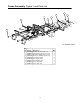
Frame Assembly- Figure 1 and Parts List 1 3 4 7 2 5 8 9 6 GD: 02000020-10/20/04 Ref. No. 1 2 3 4 5 6 7 8 9 Part No. 00022560 01000372 01001713 01003282 01003993 01005160 01008225 02000019 02000129 Description Hex Nut, 3/8-16 Flange Lock Carriage Bolt, 3/8-16 x .75 Long Bracket Assembly, Frame, Front Clevis Pin, .625 Dia x 4.375 Long Linch Pin, 3/16 Dia. Plug, Square Tube Push Retainer, 3/8 Frame Assembly Cover, Hydro Fan 3 Qty.
60" Fabricated Cutter Deck - Figure 6 37 44 41 38 22 46 45 26 39 33 4 18 9 20 6 40 23 35 19 28 36 15 18 42 7 8 3 27 13 31 2 11 2 17 16 30 43 1 21 32 23 5 17 10 34 12 12 14 12 25 29 6 24 12 12 17 GD: 01009439-01/06/05 4
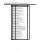
60" Fabricated Cutter Deck - Parts List for Figure 6 Ref. No. 1 2 3 4 5 6 7 8 9 10 11 12 13 14 15 16 17 18 19 20 21 22 23 24 25 26 27 28 29 30 31 32 33 34 35 36 37 38 39 40 41 42 43 44 45 46 Part No.
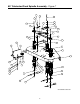
0" Fabricated Deck Spindle Assembly - Figure 7 7 11 33 10 14 22 28 5 35 27 32 25 31 30 18 13 16 34 24 28 23 6 26 27 9 36 37 19 2 20 15 8 17 1 4 18 21 25 3 2 29 12 GD: 01005433-10/21/04 6
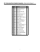
60" Fabricated Deck Spindle Assembly - Parts List for Figure 7 Ref. No. 1 2 3 4 5 6 7 8 9 10 11 12 13 14 15 16 17 18 19 20 21 22 23 24 25 26 27 28 29 30 31 32 33 34 35 36 Part No.
Hydro Tank and Hose Assembly - Figure 8 and Parts List 1 10 7 8 9 5 14 27 6 11 12 19 26 20 18 4 17 2 16 24 25 22 21 15 23 13 3 13 3 21 18 22 2 Ref. No. 1 2 3 4 5 6 7 8 9 10 11 12 13 Part No. 00006144 00012288 00012426 00012470 00013131 00017665 01004166 00022560 00030261 00031994 00012132 01000372 01004516 01002606 Description Hex Cap Screw, 3/8-16, 1 Fitting 1/2 x 3/4 - O Ring Fitting 1/2 x 1/2 - O Ring to Flare Cable Tie, 3/16 x .05 x 7.4 Hex Cap Screw, 1/4-20, .
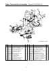
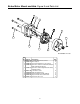
Brake Motor Mount and Hub- Figure 9 and Parts List 2 5 1 6 3 8 10 1 7 9 GD: 01008055-11/17/03 Ref. No. 1 2 3 4 Part No. 00012428 01009775 01008449 01008436 5 01008437 6 7 8 9 10 00012168 01007048 01007049 01007464 01007773 Description Qty. Lock Nut, Nylon Insert, 1/2-13 8 Motor Spacer 2 Socket Head Capscrew, 1/2-13; 6-1/2 8 Hyd. Motor, Parker Left Hand Assembly w/ 1 Brake & Drum (Not Shown) Hyd.
Brake Assembly - Figure 10 18 30 21 15 14 13 29 3 12 6 22 27 10 2 7 13 11 31 26 1 10 28 8 17 5 19 20 23 4 24 9 10 16 9 13 25 GD: 01009516-05/04/04 10
Brake Assembly - Parts List for Figure 10 Ref. No. 1 2 3 4 5 6 7 8 9 10 11 12 13 14 15 16 17 18 19 20 21 22 23 24 25 26 27 28 29 30 31 Part No. 741-0598 00011459 01000371 00012382 00012152 00022560 00027279 00071691 01000393 01000635 01000897 01002751 01002771 01003468 01003595 01003574 01003575 01003716 01008600 01008607 01008886 01008889 01009561 01009566 01009568 01009569 01009601 01009602 00013092 01000629 01000723 Description Hex Flange Bearing, .
Fuel Tank Assembly - Figure 11 and Parts List 8 9 20" Length 3 4 10 13 11 12 7 32.0" Length 2 27.5" Length 1 6 5 GD: 01007424-11/28/01 Ref. No. 1 2 3 4 5 6 7 8 9 10 11 12 13 Part No. 01000723 -00012235 01000069 01000368 00012157 01007218 01007425 01000281 01003473 00031081 00012470 01000600 Description Flat Washer, .406 ID, 1.0 OD, .105 Hose, 1/4" Fuel Line (in inches) Clamp, Union Fuel Cap, 3.5 Hex, Cap Screw, 3/8-16, .
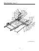
Rear Bumper - Figure 12 and Parts List 3 6 1 4 2 5 GD: 02000180-10/21/04 Ref. No. 1 2 3 4 5 6 Part No. 00012428 00022560 00030046 01003534 01009992 02000453 Description Hex Nut, 1/2-13, Insert Lock Nut, Hex 3/8-16 Flange Lock HHCS, 1/2-13, 3.00 Carriage Bolt, 3/8-16 x 2.75 Bar, Weight Rear Bumper Plate 13 Qty.
Front Caster Assembly - Figure 14 and Parts List 16 17 18 15 13 12 4 3 11 7 2 5 14 2 9 6 4 21 1 10 8 20 19 19 GD: 02000369-10/21/04 Ref. No. 1 2 3 4 5 6 7 8 9 10 11 Part No. 00023287 01006294 00060078 02000588 02000589 01000678 01006309 01006913 01007407 01006961 02000439 Description Nut, 1/2-20, Center Lock Bell Washer, 1.25 ID Grease Fitting Flat Washer, 1.00 ID Spacer, 1.005 ID x 1.25 OD x 3.6 Nut, Jam, 1.0-14, Insert Lock Hex Cap Screw, 1-14 x 5.0 Wheel, 13 x 6.
60" Wheel Assembly - Figure 15 and Parts List 2 1 GD: 01002572-09/27/00 Ref. No. Part No. Description 1 00012187 Lug Nut, 1/2-20 2 01002182 Wheel Assembly, 24 x 12-8, Dr, White: Includes 01004473 Tire, Turf Saver, 24 x 12.00-12, 2-Ply OPTIONAL TIRES 01006324 Turf Master, Rear Wheel Assembly 15 Qty.
Control Assembly- Figure 16 44 24 9 30 28 26 8 42 13 33 18 6 48 7 3 2 27 14 12 43 50 45 14 34 9 35 5 17 41 22 8 25 31 29 9 47 21 37 36 32 8 46 10 38 10 23 1 11 40 19 49 39 20 9 16 15 4 29 14 GD: 02000030-10/20/04 16
Control Assembly - Parts List for Figure 16 Ref. No. 1 2 3 4 5 6 7 8 9 10 11 12 13 14 15 16 17 18 19 20 21 Part No. 00008495 00009812 00011861 00012168 00012226 00013092 00013406 00022560 01000372 01000450 01000451 01000628 01000629 01000635 01000643 01000960 01001727 01002511 01002986 01002988 01003044 01004265 22 01003011 23 01003045 01004265 24 01004889 Description Capscrew, 3/8-16 x 1-3/4 Flat Washer, 5/16 HHCS, 3/8-16, 2.25 5/16, Lock Washer Grease Fitting, 90° HHCS, 5/16-18 x 1.
Hydro Pump Assembly- Figure 17 and Parts List 18 10 4 5 13 19 15 11 9 16 5 8 1 20 2 17 3 5 8 5 8 12 5 6 7 7 6 14 GD: 01008051-01/12/05 Ref. No. 1 2 3 4 5 6 7 8 9 10 Part No. 00012157 00012152 00019962 00020628 00022560 01000369 750-3119 01000643 00011925 01000872 Ref. Description Qty. No. Part No. Description Washer lock 3/8 zinc 2 11 01002010 Carriage Screw, 3/8-16 x 1.
Seat Assembly- Figure 18 and Parts List 4 2 5 7 8 3 6 GD: 01005780-01/10/05 1 Ref. No. 1 2 3 4 Part No. 00022560 750-3119 01000635 01010115 5 6 7 8 01001630 01002634 01002753 01000960 Description Nut, Hex 3/8-16 Flange Lock Spacer, 0.406 ID x 1.00 OD x .38 Lock Nut, Hex Flange, 5/16-18 Adjustable Seat, Black embossed, Includes Seat Switch Mounting Bracket, Seat Shoulder Screw, .50x2.345, 3/8-16 Grommet, 2.5 OD x 1.0 Long Washer 19 Qty.
27HP Kohler Engine Assembly - Figure 19 15 12 33 34 5 26 23 11 13 6 27 3 22 14 1 20 18 21 30 19 28 5 32 17 4 29 31 8 2 11 25 24 9 2 10 7 16 Description Air Filter (Primary) Air Filter (Safety) Fuel Filter Oil Filter Spark Plug Part Number KH-25-083-01-S KH-25-083-04-S KH-25-050-08-S KH-12-050-08 759-3336 GD: 01008286-10/11/04 20
27HP Kohler Engine Assembly - Parts List for Figure 19 Ref No Part No. Description Qty. 1 00005763 Hex Nut, 7/16-14 1 2 00006129 HHCS, 5/16-18, 1-3/4 4 3 00014602 Round Hd. Machine Screw, 10-32 x 3/4 2 4 00014608 Lock Nut, Nylon Insert, 10-32 2 5 00022560 Flange Lock, Hex Nut, 3/8-16 2 6 00060056 Nut Washer, W/Star, 8-32 2 7 00060078 Grease Fitting, 1/4-28 x 3/16 1 8 01000199 Extension Spring, 1.0 OD x 5.125 1 9 01000302 Shoulder Screw, 7/16-14 1 10 01000364 Hex Carriage Screw, 3/8-16, 1.
25HP Kawasaki Engine Assembly - Figure 20 17 14 26 29 3 32 8 27 16 1 15 13 4 20 25 23 22 6 7 24 28 31 5 2 33 21 10 19 34 30 13 11 12 9 18 Description Air Filter Air Filter (Inner) Fuel Filter Oil Filter Spark Plug Part Number KM-11013-7020 KM-11013-7019 KM-49019-7001 KM-49065-2078 KM-BPR4ES GD: 01007227-10/11/04 22
25HP Kawasaki Engine Assembly - Parts List for Figure 20 Ref No 1 2 3 4 5 6 7 8 9 10 11 12 13 14 15 16 17 18 19 20 21 22 23 24 25 26 27 28 29 30 31 32 33 34 Part No. 00005763 00006129 01000811 00014602 00014608 01005856 00022560 00060056 00060078 01000199 01000302 01000364 01000389 01000635 01000721 01000728 00012169 01001395 01001979 01002601 01006456 01003269 01003271 01003272 01003283 01008525 01004004 01004081 01009299 01005006 01007015 01008623 01005104 01005314 Description Qty.
Electrical Assembly Kohler - Figure 23 16 5 1 4 12 2 20 25 14 22 24 9 18 21 7 6 17 8 11 26 15 19 13 Fasten relay (01002251) with self-tapping screw (01000443) on LH control panel shown in Fig. 16.
Electrical Assembly Kohler - Parts List for Figure 23 Ref. No. 1 2 3 4 5 6 7 8 9 10 11 12 13 14 15 16 17 18 19 20 21 22 23 24 25 26 Part No. 00012032 00012289 00012470 00013131 00013258 00014608 00030906 00032097 01000628 01001811 01002111 01002766 01003581 01003649 01004040 01004078 01005389 01008042 01009905 01009995 02000024 02000165 02000592 02000349 02000348 01002251 Description Battery, 12V 225CCA 30 Min Cable, Battery, Red, 36" Tie, Cable, 3/16 x .05 x 7.4" Screw, Hex, Cap, 1/4-20 x .
25HP Electrical Assembly Kawasaki - Figure 24 19 1 5 15 6 10 24 5 29 21 7 3 14 17 2 26 28 11 22 25 8 7 20 9 13 30 18 23 4 16 Fasten relay (01002251) with self-tapping screw (01000443) on LH control panel shown in Fig. 16.
25HP Electrical Assembly Kawasaki - Parts List for Figure 24 Ref. No. 1 2 3 4 5 6 7 8 9 10 11 12 13 14 15 16 17 18 19 20 21 22 23 24 25 26 27 28 29 30 Part No. 00012032 00012152 00012165 00012470 00013131 00013258 00014608 00030906 00032097 00095773 01000628 01001811 01002111 01002228 01002766 01003581 01003649 01004040 01004078 01005389 01005406 01008042 01009905 01009995 02000024 02000165 02000591 02000349 02000348 01002251 Description Qty.
Lift Assembly - Figure 25 19 27 26 5 18 41 5 34 5 33 17 10 7 9 39 2 3 46 7 12 6 25 40 13 17 22 32 23 47 14 38 4 45 5 37 29 24 15 35 22 20 11 7 16 43 36 44 4 27 28 8 31 21 28 42 30 1 GD: 01008452-11/22/04 28 9
Lift Assembly - Parts List for Figure 25 Ref. No. 1 2 3 4 5 6 7 8 9 10 11 12 13 14 15 16 17 18 19 20 21 22 23 24 25 26 27 28 29 30 31 32 33 34 35 36 37 38 39 40 41 42 43 44 45 46 47 Part No.
Foot Pedal Deck Lift Assembly - Figure 26 and Part List 5 2 3 9 8 12 11 1 7 4 6 10 12 1 GD: 01008360-05/06/03 Ref. No. 1 2 3 4 5 6 7 8 9 10 11 12 Part No. 00012152 00012577 01006786 00013131 00022560 01000944 01004118 01006409 01006352 01008359 01006418 00062715 Description Lock Nut, Nylon Insert, 1/4-20 Washer, 1/2 x 1 Shim Detent Pin w/12" Lanyard Hex Cap Screw, 1/4-20, .75 Hex Nut, Flange Lock 3/8-16 Hex Cap Screw, 1/4-20, 1.00 Shoulder Screw, .50 x .27 Lg.
Floor Panel Assembly- Figure 27 and Parts List 2 5 12 4 6 8 13 9 1 7 3 10 11 GD: 02000360-10/21/04 Ref. No. 1 2 3 4 5 6 7 8 9 10 11 12 13 Part No. 00012132 00012158 00013131 00014608 00021956 00030906 00083192 01001170 01001638 01004992 02000361 02000362 02000433 Description Qty. Lock Washer, 1/4 2 Washer AR Hex Cap Screw, 1/4-20, .75 2 Lock Nut, Nylon Insert, 10-32 3 Hair Pin, 3/8-1/2 2 Screw, Phillips Head, Machine, 10-32 x 5/8 3 Washer 2 Rubber Bumper, .62 OD x .
Cub Cadet Commercial P.O. Box 368023 Cleveland, OH 44136 Form No. 02000530 Rev.