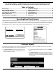
Safety • Assembly • Operation • Adjustments • Maintenance • Troubleshooting • Parts Lists • Warranty OPERATOR’S MANUAL Zero Turn Riding Mower Time Saver Models i1046 i1050 IMPORTANT READ SAFETY RULES AND INSTRUCTIONS CAREFULLY BEFORE OPERATION Warning: This unit is equipped with an internal combustion engine and should not be used on or near any unimproved forest-covered, brushcovered or grass-covered land unless the engine’s exhaust system is equipped with a spark arrester meeting applicable local or sta
This Operator’s Manual is an important part of your new lawn mower. It will help you assemble, prepare, and maintain the unit for best performance. Please read and understand what it says. Table of Contents Slope Gauge............................................................... 3 Safe Operation Practices........................................... 4 Setup and Adjustment............................................... 8 Operating Your Lawn Mower.................................... 10 Making Adjustments ...
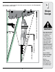
Use this page as a guide to determine slopes where you may not operate safely. Do not operate your lawn mower on such slopes. 1 Slope Gauge 3IGHT AND HOLD THIS LEVEL WITH A VERTICAL TREE &O OR A FENCE POST OR A CORNER OF A BUILDING OT LD ALO NG D ESEN TED L I N E REPR LOPE TS A S WARNING Do not mow on inclines with a slope in excess of 15 degrees (a rise of approximately 2-1/2 feet every 10 feet). A riding mower could overturn and cause serious injury.
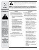
2 Safe Operation Practices WARNING This symbol points out important safety instructions which, if not followed, could endanger the personal safety and/or property of yourself and others. Read and follow all instructions in this manual before attempting to operate this machine. Failure to comply with these instructions may result in personal injury. When you see this symbol.
General Operation: 14. Watch for traffic when operating near or crossing roadways. This machine is not intended for use on 1. Read, understand, and follow all instructions on the any public roadway. machine and in the manual(s) before attempting to 15. Do not operate the machine while under the influassemble and operate. Keep this manual in a safe ence of alcohol or drugs. place for future and regular reference and for ordering 16. Mow only in daylight or good artificial light. replacement parts. 2.
2 Safe Operation Practices This symbol points out important safety instructions which, if not followed, could endanger the personal safety and/or property of yourself and others. Read and follow all instructions in this manual before attempting to operate this machine. Failure to comply with these instructions may result in personal injury. When you see this symbol.
Service 1. 2. 3. 4. 5. 6. 7. 8. 9. 10. Never attempt to make adjustments or repairs to the machine while the engine is running. Never run an engine indoors or in a poorly ventilated 11. Grass catcher components and the discharge area. Engine exhaust contains carbon monoxide, an cover are subject to wear and damage which could odorless, and deadly gas. expose moving parts or allow objects to be thrown.
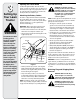
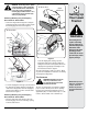
3 Setting Up Your Lawn Tractor Opening the Tractor Hood Gas and Oil Fill-up To attach the negative battery cable and check the engine oil level the hood must be open. Locate the hood lift notch (Refer to Figure 4 on page 10) at the front/center of the dash panel. Grasping the hood at the notch, lift and pivot the hood forward to open. WARNING: Use extreme care when handling gasoline. Gasoline is extremely flammable and the vapors are explosive.
WARNING: The mowing deck is capable of throwing objects. Never operate the mower deck without the chute deflector in its down position, even with the mulching plug installed. Failure to do so could result in serious personal injury and/or property damage.
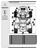
4 Know the Controls Read this owner’s manual and safety rules before operating your lawn mower. Compare the figure below with your lawn tractor to learn about the location and purpose of various controls and adjustments. Save this manual for future reference. It is very important to follow the instructions and operate the controls properly. Q Operation A C B E D NOTE: Any reference in this manual to the RIGHT or LEFT side of the tractor is observed from operator’s position.
Throttle Control Lever The throttle control lever controls the speed of the engine. When set in a given position, the throttle Fast will maintain a uniform engine Position speed. IMPORTANT: When operating the tractor with the cutting deck engaged, throttle control lever must always be in the FAST (rabbit) position. Slow Position Choke Control The choke control knob is located on the lower left side of the dash panel and is activated by pulling outward.
4 Operation Systems Indicator Monitor/Hour Meter Oil Pressure Indicator Light This warning lamp indicates low engine oil pressure. If this indicator illuminates, stop the tractor immediately and check the engine oil level. If the oil level is within the operating range, but the light remains on, contact your Cub Cadet dealer. NOTE: The oil pressure indicator may illuminate when the key switch is turned to an on position, but should turn off when the engine is started.
Cargo Net WARNING: Tampering with or attempting to bypass the Safety Interlock Switches in any way will void your tractor’s warranty. Do not operate the tractor if the interlock system is malfunctioning. Conveniently located on the tractor’s dash panel, the cargo net can be used to store personal items while operating the lawn tractor. Hydro Transmission Bypass Rods Reverse Caution Mode The hydro transmission bypass rods are located at the back of the tractor above the rear hitch plate.
4 Operation Starting the Engine Stopping the Engine NOTE: Refer to the TRACTOR SET-UP on page 8 of this manual for gasoline and oil fill-up instructions. 1. Insert the tractor key into the key switch module. WARNING: If you strike a foreign object, stop the engine and disconnect the spark plug wire(s). Thoroughly inspect the machine for any damage. Repair damage before restarting. 2. Disengage the PTO (Blade Engage) lever/knob. 3. Engage the tractor’s parking brake. 1.
Steering the Tractor Your i1000 series tractor is equipped with an innovative steering design which is somewhat different from that of the traditional steering wheel type lawn tractor. Turning the steering wheel not only turns the front wheels, but also controls the drive linkage of the two hydro transmissions that drive the tractor. This feature allows you to vary the radius of turns from a normal wide turn down to a zero turn.
4 Operation • • • Under heavier conditions it may be necessary to go back over the cut area a second time to get a clean cut. Do not attempt to mow heavy brush and weeds and extremely tall grass. Your tractor is designed to mow lawns, not clear brush. Keep the blades sharp and replace the blades when worn. Refer to Cutting Blades on page 25 of this manual for proper blade sharpening instructions. WARNING The mowing deck is capable of throwing objects.
Making Adjustments 3. Once the desired position is reached, release the seat lever. Slide the seat slightly fore and aft as necessary to engage the seat lever into one of the eight adjustWARNING: Never attempt to make ment positions in the index plate. Make certain the any adjustments while the engine is seat is locked in position. running, except where specified in the operator’s manual. Disconnect spark plug wire(s) before performing any Leveling the Deck adjustments, repairs or maintenance.
5 Making Adjustments WARNING Never attempt to make any adjustments while the engine is running, except where specified in the operator’s manual. Stop the engine before performing any adjustments. Front To Rear Leveling Deck Gauge Wheel Adjustment The front of the cutting deck is supported by an adjustable front deck hanger rod. This rod can be adjusted to set the front to rear pitch of the deck. The front of the deck should be between 1/4-inch and 3/8-inch lower than the rear of the deck.
Deck Rear Roller Adjustment The rear rollers on the mower deck are not designed to carry the weight of the deck. The rear rollers should be adjusted to approximately 1/4" to 1/2" above the ground when the deck is moved to the desired cutting height. Place the tractor on a smooth, flat surface, move the deck to the desired cutting height, and check the height of the rear rollers.
6 Maintaining Your Tractor Maintaining Your Lawn Tractor 10w30 5W20, 5W30 Checking Engine Oil Level Check engine oil level before each use as follows: • Place the tractor on a flat surface and stop the engine. Allow the engine to cool long enough for the oil to drain into the engine sump. • Clean the area around the oil dipstick/fill cap. unscrew the dipstick/fill cap from the fill tube on the engine. Remove the dipstick and wipe the oil off.
threaded hole. Stop pouring when the oil reaches the bottom of the threads. Allow a few minutes for the oil to be absorbed by the filter material. • Apply a thin coat or new oil on the rubber gasket of the new oil filter. • Install the new oil filter on the filter adapter. Hand tighten until the filter gasket contacts the adapter, then tighten the filter an additional 3/4-1 turn. • Refill the engine with the proper type oil. The engine oil capacity is approximately 1.7-1.9 quarts (1.6 -1.8 L).
6 Steering Maintenance • Check the gap using a wire feeler gauge. Adjust the gap to .030 in. (0.76mm) by carefully bending the ground electrode. See Figure 19. Steering Lubrication The steering arms, pivot shafts, and axles must be lubricated if ever the steering effort increases, or after every 25 hour of operation. Lubricate using a pressure grease gun and Cub Cadet 251H EP grease, or an equivalent No. 2 multipurpose lithium grease.
3. If there is no side play, lower the tractor to the ground and have the steering linkage inspected by you Cub Cadet dealer. If there is side play, tighten the pivot bar as follows: • Support the pivot bar, then remove the hex lock nuts securing the two shoulder bolts that pass through the pivot bar bracket, the pivot bar, and frame. Refer to Figure 20. • Slide a half inch flat washer, with a maximum thichness of .030 inch, onto each shoulder bolt.
6 Maintaining Your Tractor Tires 2. Connect the other jumper cable to the negative terminal of the good battery, then to the frame of the unit with the dead battery. WARNING: Never exceed the maximum inflation pressure shown on the sidewall of tire. WARNING: Failure to use this procedure could cause sparking, and the gas in either battery could explode.
7. Move the deck lift lever into the top notch on the right fender to raise deck lift arms up and out of the way. 8. Carefully slide the cutting deck forward and remove the deck belt from around the tractor’s PTO pulley on the bottom of the engine. 9. Continue to roll the deck toward the front of the tractor until the front deck hanger rod can be removed from the slots of the hanger bracket at the front of the deck. 10.
6 Maintaining Your Tractor Fuses • A 20 amp fuse is installed in your tractor’s wiring harness to protect the tractor’s electrical system from damage caused by excessive amperage. • If the electrical system does not function, or your tractor’s engine will not crank, first check to be certain that the fuse has not blown. • The fuse can be found inside of the dash panel behind the battery tray. You may need to remove the battery to gain access to the fuse.
• After first making sure the deck belt is properly engaged in all of the deck pulleys, route the deck belt forward through the center of the front deck hanger rod and toward the PTO pulley on the bottom of the engine. • Using the deck lift handle, raise the deck to the position that gives you the most horizontal run of the belt between the deck pulleys and the PTO pulley on the bottom of the engine.
6 Maintaining Your Tractor Maintenance Schedule Before Each Use Every 10 Hours Every 25 Hours Every 50 Hours Every 100 Hours Prior to Storing Check Engine Oil Level Check Air Cleaner Check Engine Air Intake Areas & Clean as Needed Clean and Re-oil Air Filter’s Foam Precleaner Check Air Cleaner Paper Element & Clean as Needed Replace Air Cleaner Paper Element & Precleaner Change Engine Oil & Filter IMPORTANT IMPORTANT: Failure to perform the scheduled maintenance may void your warranty.
If the machine is to be inoperative for a period longer than 30 days, the following procedures are recommended: • Drain any large volume of fuel from the tank by disconnecting the fuel line from the in-line fuel filter near the engine. • Reconnect the fuel line and run the engine until it starts to falter, then use the choke to keep the engine running until all fuel in the carburetor has been exhausted. • Again disconnect the fuel line and drain any remaining gasoline from the system.
8 Warning/Instruction Label On Center of Fender Running Board Safety Labels DANGER • • • • TO START 1. DISENGAGE BLADES/PTO, (POWER TAKE OFF) ROTATING BLADES CAUSE SERIOUS INJURY OR DEATH DO NOT MOW WHEN CHILDREN OR OTHERS ARE AROUND NEVER CARRY CHILDREN EVEN WITH BLADE(S) OFF. LOOK DOWN AND BEHIND BEFORE AND WHILE BACKING. MOWING IN REVERSE IS NOT RECOMMENDED. 2. ENGAGE THE TRACTOR’S PARKING BRAKE. 3. SET THROTTLE TO FAST “RABBIT” POSITION AND PULL CHOKE KNOB OUT. 4. TURN KEY TO START ENGINE.
Problem Engine fails to start Cause 1. PTO engaged. 2. Spark plug wire(s) disconnected. 3. Fuel tank empty or stale fuel. 4. Choke not activated. 5. Faulty spark plug. 6. Blocked fuel line. 7. Engine flooded. 8. Parking brake not engaged. 9. Throttle control lever not in correct starting position. Engine runs erratic 1. Unit running with CHOKE applied. 2. Spark plug wire(s) loose. 3. Blocked fuel line or stale fuel. 4. Vent in gas cap plugged. 5. Water or dirt in fuel system. 6. Dirty air cleaner.
9 Trouble Shooting Problem Steering effort increases 1. Lack of Lubrication. 2. Debris in steering gears. Remedy 1. Apply grease through six lube fittings on axle pivot bar and steering arms. 2. Remove steering gear covers and clean gears. Tight spot in steering or steering jams 1. Debris in steering gears. 1. Remove steering gear covers and clean gears. Excessive play when turning steering wheel 1. Side play between axle pivot bar and pivot bar bracket/frame. 1.
NOTE: Contact your Cub Cadet dealer to order replacement parts. If you do not have a dealer, call the Customer Dealer Referral Line at 1-877-282-8684 or visit www.cubcadet.com to find the nearest Cub Cadet dealer in your area. Time SaverTM Lawn Tractor Description Model i1046 Replacement Parts Model i1050 Lower Drive Belt - Contact Dealer 954-04134 954-04134 Engine to Deck/ Deck Spindle Belt 954-04118 954-04077 942-04124 (Qty. 1) 942-04053A (Qty.
KOHLER CO. FEDERAL AND CALIFORNIA EMISSION CONTROL SYSTEMS LIMITED WARRANTY UTILITY AND LAWN AND GARDEN ENGINES The U.S. Environmental Protection Agency (EPA), the California Air Resources Board (CARB), and Kohler Co. are pleased to explain the Federal and California Emission Control Systems Warranty on your small off-road equipment engine. For California, engines produced in 1995 and later must be designed, built and equipped to meet the state’s stringent anti-smog standards.
CALIFORNIA EMISSION CONTROL WARRANTY STATEMENT YOUR WARRANTY RIGHTS AND OBLIGATIONS The California Air Resources Board and MTD Consumer Group Inc are pleased to explain the evaporative emission control system warranty on your 2007 lawn mower. In California, new lawn mower must be designed, built and equipped to meet the State’s stringent anti-smog standards.
CUB CADET LLC MANUFACTURER’S LIMITED WARRANTY FOR SERIES 1000 & SERIES 1500 TRACTORS IMPORTANT: To obtain warranty coverage owner must present an original proof of purchase and applicable maintenance records to the servicing dealer. Please see the operator’s manual for information on required maintenance and service intervals.