Safe Operation Practices • Set-Up • Operation • Maintenance • Service • Troubleshooting • Warranty Operator’s Manual Zero Turn Riding Mower Time Saver Models i1046 i1050 WARNING READ AND FOLLOW ALL SAFETY RULES AND INSTRUCTIONS IN THIS MANUAL BEFORE ATTEMPTING TO OPERATE THIS MACHINE. FAILURE TO COMPLY WITH THESE INSTRUCTIONS MAY RESULT IN PERSONAL INJURY. CUB CADET LLC, P.O. BOX 361131 CLEVELAND, OHIO 44136-0019 Printed In USA FORM NO.
1 To The Owner Thank You Thank you for purchasing a Lawn Tractor manufactured by Cub Cadet LLC. It was carefully engineered to provide excellent performance when properly operated and maintained. Please read this entire manual prior to operating the equipment. It instructs you how to safely and easily set up, operate and maintain your machine. Please be sure that you, and any other persons who will operate the machine, carefully follow the recommended safety practices at all times.
2 Important Safe Operation Practices WARNING: This symbol points out important safety instructions which, if not followed, could endanger the personal safety and/or property of yourself and others. Read and follow all instructions in this manual before attempting to operate this machine. Failure to comply with these instructions may result in personal injury. When you see this symbol.
c. When practical, remove gas-powered equipment from the truck or trailer and refuel it on the ground. If this is not possible, then refuel such equipment on a trailer with a portable container, rather than from a gasoline dispenser nozzle. 7. Plan your mowing pattern to avoid discharge of material toward roads, sidewalks, bystanders and the like. Also, avoid discharging material against a wall or obstruction which may cause discharged material to ricochet back toward the operator. d.
25. 26. 27. 28. 29. Disengage all attachment clutches, depress the brake pedal completely and shift into neutral before attempting to start engine. Your machine is designed to cut normal residential grass of a height no more than 10”. Do not attempt to mow through unusually tall, dry grass (e.g., pasture) or piles of dry leaves. Dry grass or leaves may contact the engine exhaust and/or build up on the mower deck presenting a potential fire hazard.
5. 6. Check the blade(s) and engine mounting bolts at frequent intervals for proper tightness. Also, visually inspect blade(s) for damage (e.g., excessive wear, bent, cracked). Replace the blade(s) with the original equipment manufacturer’s (O.E.M.) blade(s) only, listed in this manual. “Use of parts which do not meet the original equipment specifications may lead to improper performance and compromise safety!” Mower blades are sharp.
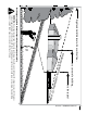
d o t t e d lin 15° s l o p e) or a fence post repr e s e n ts a e( or a corner of a building... ng Fold a lo Sight and hold this level with a vertical tree... 15° Use this page as a guide to determine slopes where you may not operate safely. WARNING: Do not operate your lawn mower on such slopes. Do not mow on inclines with a slope in excess of 15 degrees (a rise of approximately 2-1/2 feet every 10 feet). A riding mower could overturn and cause serious injury.
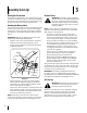
3 Assembly & Set-Up Opening the Tractor Hood Gasoline Fill-up WARNING: Use extreme care when handling gasoline. Gasoline is extremely flammable and the vapors are explosive. Never fuel machine indoors or while the engine is hot or running. Extinguish cigarettes, cigars, pipes, and other sources of ignition. To attach the negative battery cable and check the engine oil level the hood must be open. Locate the hood lift notch at the front/center of the dash panel.
Mulching Plug & Shipping Brace Removal WARNING!: Make sure the riding mower’s engine is off, remove the ignition key, and set the parking brake before removing the shipping brace. WARNING!: The shipping brace, used for packaging purposes only, must be removed and discarded before operating your riding mower. WARNING!: The mowing deck is capable of throwing objects. Never operate the mower deck without the chute deflector in its down position, even with the mulching plug installed.
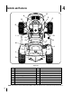
4 Controls and Features R A C B E D G I Q P F K H J L O M N Figure 4-1 A Systems Indicator Monitor/ Hour Meter J Deck Lift Lever B Throttle Control Lever K Cup Holder C Key Switch Module L Seat Adjustment Lever D Choke Control Knob M Fuel Fill Cap E PTO (Blade Engage)Control Switch N Hydro Transmission Bypass Rods F Parking Brake Lever O Fuel Level Window G Forward Control Pedal P Cargo Net H Reverse Control Pedal Q 12 V Power Outlet I Brake Pedal R Hood Lift
Systems Indicator Monitor/Hour Meter Your tractor is equipped with a Systems Indicator Monitor as shown in Figure 5. The monitor records the accumulated hours of tractor operation, and displays the information on the LCD hour meter display (tenths of an hour - right most digit). The monitor also has four indicator lights that show the status of various functions of the tractor. Oil Battery LCD Hour Meter 123.4 and check the engine oil level.
Choke Control The choke control knob is located on the lower left side of the dash panel and is activated by pulling outward. Activating the choke control closes the choke plate on the carburetor and aids in starting the engine. PTO (Blade Engage) Control Switch To engage the electric PTO and provide power to the cutting deck, pull outward on the PTO control switch knob. Push the switch knob inward to disengage the PTO and stop the cutting deck.
5 Operation WARNING Reverse Caution Mode • DO NOT OPERATE THE UNIT WHERE IT COULD SLIP OR TIP. • IF MACHINE STOPS GOING UPHILL, STOP BLADE(S) AND BACK DOWNHILL SLOWLY. • DO NOT MOW WHEN CHILDREN OR OTHERS ARE AROUND. WARNING: Use extreme caution while operating the tractor in the REVERSE CAUTION MODE. Always look down and behind before and while backing. Do not operate the tractor when children or others are around. Stop the tractor immediately if someone enters the area.
Starting the Engine WARNING: Do not operate the tractor if the interlock system is malfunctioning. This system was designed for your safety and protection. NOTE: Refer to the engine Owner’s Manual for gasoline and oil fill-up instructions. 1. Insert the tractor key into the key switch module. 2. Disengage the PTO (Blade Engage) lever/knob. 3. Engage the tractor’s parking brake. 4. Pull the choke control knob outward into the full choke position (a warm engine may not require choking). 5.
the desired turn. Turn the steering wheel back to the center position as the turn is completed. NOTE: It is not necessary to release the drive pedal when making a turn. The change to the transmission linkage occurs regardless of how far the drive pedal is depressed. When the steering wheel is straightened, the tractor will return to the speed set by the drive pedal.
Mulching The i1000 series tractor decks are equipped with a mulching kit. The mulch kit which incorporates special blades, already on your tractor, in a process of recirculating grass clippings repeatedly beneath the cutting deck. The ultra-fine clippings are then forced back into the lawn where they act as a natural fertilizer. Observe the following points for best results when mulching: • Never attempt to mulch if the lawn is damp.
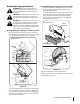
6 Maintenance & Adjustments Maintenance Warning! Before performing any maintenance or repairs, disengage the PTO, move the drive control levers fully outward in the neutral position, engage the parking brake, stop the engine and remove the key to prevent unintended starting. Engine Refer to the Kohler Owner’s Manual for all engine maintenance intervals, procedures, specifications and instructions.
Cleaning Steering Gears Using Deck Wash System™ Once a year, or if a tight spot is experienced when turning the steering wheel, remove the steering gear cover on each end of the pivot bar and clean the two steering gears. • From beneath the cover base plate on each end of the pivot bar, remove the three hex screws securing the steering gear cover. Remove the covers and clean the gears. It is not necessary to lubricate the gears. Refer to Figure 6-2.
Moving the Tractor Manually If for any reason the tractor will not drive or you wish to move the tractor, engage the two hydro transmission bypass rods to manually move the tractor short distances. IMPORTANT: Never tow or drag the tractor with the rear wheels on the ground. Even with the bypass rods engaged. Doing so will damage the transmissions. To engage a bypass rod, pull the rod rearward so that the flange on the rod passes through the larger/rounded part of the keyhole slot.
3. Working from the left side of the tractor, loosen, but do not remove, the hex cap screw on the left deck hanger bracket.Working from the left side of the tractor, loosen, but do not remove, the hex cap screw in the left deck adjustment bracket. See Figure 6-6. 50” Mower Deck Shown 4. Use a open end wrench to turn the inner hex nuts to adjust the front of the deck. Turn the hex nuts clockwise to raise the front of the deck, or counterclockwise to lower the front of the deck.
• Secure the roller assembly with the four self tapping screws. Refer to Figure 6-9. NOTE: The self tapping screws should be in the corresponding holes of both the left and right roller index brackets. Lock Nut Front Index Bracket Shoulder Bolt 50" Deck ONLY The 50" deck roller assembly index bracket has five adjustment positions holes. • While supporting the roller assembly, remove click pin and withdraw the clevis pin from both the left and right roller index brackets. See Figure 6-10. Index Brkt.
Maintenance Schedule Before Each use Check Air Filter for Dirty, Loose or Damaged Parts Every 25 Hours P P P Change Engine Oil and Replace Oil Filter P P P P P Lube Mid Steering Arms, Pivot Shafts, and Axles Lube Front Wheel Bearings Clean Engine Cooling Fins Lube Front Deck Wheels P Lube Pedal Pivot Points Check Spark Plug Condition & Gap Replace Fuel Filter 22 Section 6— Maintenance & Adjustments Prior to Storing P Replace Air Filter Element Lube Deck Spindles and Idler Bracket Every 100 Ho
7 Service Pivot Bar adjustment If excessive play is experienced in the steering wheel, check the pivot bar for forward/rearward movement. 1. Raise the front of the tractor and set it on jack stands, so the front wheels are suspended above the ground. 2. Grasping the ends of the pivot bar, attempt to move each end of the axle forward and rearward to check for side play. There should be minimal or no side play. 3.
IMPORTANT: Never jump your tractor’s dead battery with the battery of a running vehicle. 1. Connect end of one jumper cable to the positive terminal of the good battery, then the other end to the positive terminal of the dead battery. 2. Connect the other jumper cable to the negative terminal of the good battery, then to the frame of the unit with the dead battery. WARNING!: Failure to use this procedure could cause sparking, and the gas in either battery could explode. 10.
• It is important that each cutting blade edge be ground equally to maintain proper blade balance. • A poorly balanced blade will cause excessive vibration and may cause damage to the tractor and result in personal injury. The blade can be tested by balancing it on a round shaft screwdriver. Grind metal from the heavy side until it balances evenly. IMPORTANT: When replacing the blades, make certain the side of the blade marked ‘‘Bottom’’ faces the ground when the mower is turned to the operating position.
NOTE: References to left and right are from the front of the tractor in the following instructions. • • Pull the right side of the belt forward and place the narrow V side of the belt into the PTO pulley. While holding the belt and pulley together, rotate the pulley to the left. Continue holding and rotating the pulley and belt until the belt is fully rolled into the PTO pulley. Refer to Figure 7-6. WARNING!: Use caution to prevent pinching your fingers when rolling the belt onto the PTO pulley.
Off Season Storage If the machine is to be inoperative for a period longer than 30 days, the following procedures are recommended: WARNING: Never store the machine or fuel container indoors where there is an open flame, spark or pilot light such as on water heater, furnace, clothes dryer or other gas appliance. IMPORTANT: Fuel left in the fuel tank during warm weather deteriorates and will cause serious starting problems.
8 Troubleshooting Problem Engine fails to start Remedy 1. PTO/Blade Engage knob engaged. 1. Place knob in disengaged (OFF) position. 2. Parking brake not engaged. 2. Engage parking brake. 3. Spark plug wire(s) disconnected. 3. Connect wire(s) to spark plug(s). 4. Throttle control lever not in correct starting position. 4. Place throttle lever to FAST position. 5. Choke not activated 5. Pull the CHOKE control outward. 6. Fuel tank empty, or stale fuel. 6.
9 Replacement Parts Contact your Cub Cadet dealer to order replacement parts. If you do not have a dealer, call the Customer Dealer Referral Line at 1-877282-8684 or visit www.cubcadet.com to find the nearest Cub Cadet dealer in your area. Phone (800) 965-4CUB to order replacement parts or a complete Parts Manual (have your full model number and serial number ready). Parts Manual downloads are also available free of charge at www.cubcadet.com.
Attachments & Accessories 10 The following attachments and accessories are availalbe for the Model i1046 and/or i1050 Lawn Tractors. See the retailer from which you purchased your tractor, or an authorized Cub Cadet Dealer for information regarding price and availability.
CALIFORNIA EMISSION CONTROL WARRANTY STATEMENT YOUR WARRANTY RIGHTS AND OBLIGATIONS The California Air Resources Board and MTD Consumer Group Inc are pleased to explain the evaporative emission control system warranty on your 2008 lawn mower. In California, new lawn mower must be designed, built and equipped to meet the State’s stringent anti-smog standards.
CUB CADET LLC MANUFACTURER’S LIMITED WARRANTY FOR SERIES 1000 & SERIES 1500 TRACTORS IMPORTANT: To obtain warranty coverage owner must present an original proof of purchase and applicable maintenance records to the servicing dealer. Please see the operator’s manual for information on required maintenance and service intervals. In the U.S.A.: Check your Yellow Pages, or contact Cub Cadet LLC at P.O. Box 361131, Cleveland, Ohio 44136-0019, call 1-877-282- 8684 or log on to our website at www.cubcadet.com.