Safe Operation Practices • Set-Up • Operation • Maintenance • Service • Troubleshooting • Warranty Operator’s Manual HP LS 27 CC — Log Splitter WARNING READ AND FOLLOW ALL SAFETY RULES AND INSTRUCTIONS IN THIS MANUAL BEFORE ATTEMPTING TO OPERATE THIS MACHINE. FAILURE TO COMPLY WITH THESE INSTRUCTIONS MAY RESULT IN PERSONAL INJURY. CUB CADET LLC, P.O. BOX 361131 CLEVELAND, OHIO 44136-0019 Printed In USA Form No.
1 To The Owner Thank You Thank you for purchasing a Cub Cadet Log Splitter. It was carefully engineered to provide excellent performance when properly operated and maintained. Please read this entire manual prior to operating the equipment. It instructs you how to safely and easily set up, operate and maintain your machine. Please be sure that you, and any other persons who will operate the machine, carefully follow the recommended safety practices at all times.
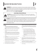
2 Important Safe Operation Practices WARNING! This symbol points out important safety instructions which, if not followed, could endanger the personal safety and/or property of yourself and others. Read and follow all instructions in this manual before attempting to operate this machine. Failure to comply with these instructions may result in personal injury. When you see this symbol.
If your machine is equipped with an internal combustion engine and is intended for use near any unimproved forest, brush, or grass covered land, the engine exhaust should be equipped with a spark arrestor. Make sure you comply with applicable local, state, and federal codes. Take appropriate firefighting equipment with you. c. Never fuel machine indoors. d. Never remove gas cap or add fuel while the engine is hot or running. e. Allow engine to cool at least two minutes before refueling. 14.
11. When splitting in the vertical position, stabilize the log before moving the control handle. Split as follows: a. Place log on the end plate and turn until it leans against the beam and is stable. b. When splitting extra large or uneven logs, the log must be stabilized with wooden shims or split wood placed between the log and end plate or ground. 12. Always keep fingers away from any cracks that open in the log while splitting. They can quickly close and pinch or amputate your fingers. 13.
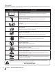
Safety Symbols This page depicts and describes safety symbols that may appear on this product. Read, understand, and follow all instructions on the machine before attempting to assemble and operate. Symbol Description READ THE OPERATOR’S MANUAL(S) Read, understand, and follow all instructions in the manual(s) before attempting to assemble and operate WARNING— CRUSHING HAZARD Keep hands away from wedge, end plate, partially split wood and moving parts.
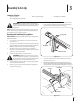
3 Assembly & Set-Up Contents of Carton • One Log Splitter • One Engine Operator’s Manual • One Tongue Assembly WARNING! Use extreme caution unpacking this machine. Some components are very heavy and will require additional people or mechanical handling equipment. 7. • One Operator’s Manual Remove the spring clip and clevis pin from the jack stand on the tongue and then pivot the jack stand towards the ground into the operating position. See Fig. 3-1.
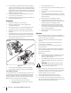
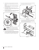
10. Align the holes in the tongue with the holes in the tank bracket and secure with the hardware just removed. See Fig. 3-2. 14. Disconnect the dislodger from the beam weld bracket by removing the six hex screws. See Fig. 3-4. NOTE: The high pressure hose, which runs from the gear pump to the bottom of the control valve, must be above the tongue assembly. 11. The log splitter is shipped with the beam in a vertical position. Remove any bolts or straps securing the end plate to the bottom of the crate.
16. Lift and slide the cylinder up to the top of beam and into the weld brackets. See Fig. 3-6. Cylinder 20. Cut the metal strap securing the log splitter to the bottom of the crate and remove the wood under the engine and/or any other wood, then roll the log splitter off the bottom of the shipping crate. 21. The control handle is shipped hanging from the valve on the handle link. 22. Remove the clevis pin and bow-tie cotter pin from the control handle. See Fig. 3-8.
Set-Up 3. Gas and Oil Fill-Up NOTE: Approved fluids include Shell Tellus® S2 M 32 Hydraulic Fluid, Dexron® III/Mercon® automatic transmission fluid, Pro-Select™ AW-32 Hydraulic Oil or 10WAW-ISO viscosity grade 32 hydraulic oil. It is not recommended that fluids be mixed, to top off the reservoir tank during initial set-up use Shell Tellus® S2 M 32 Hydraulic Fluid only. Service the engine with gasoline and oil as instructed in the engine manual packed with your log splitter.
4 Controls & Features Cylinder Log Dislodger Control Handle Horizontal Beam Lock Tongue Wedge Beam Log Tray End Plate Jack Stand Vertical Beam Lock Engine Controls Figure 4-1 See the Engine Operator’s Manual for the location and function of the controls on the engine. Beam Locks These two locks, as their name suggests, are used to secure the beam in the horizontal or the vertical position. The vertical beam lock is located next to the oil filter.
5 Operation Starting & Stopping the Engine b. To lock the beam in the vertical position, pull out on the vertical beam lock and rotate it to secure the beam. See Fig. 5-2. Refer to the Engine Operator’s manual packed with your log splitter for instructions on starting and stopping the engine. Using the Log Splitter Operating Positions 1. Place the log splitter on flat, dry, solid ground. 2. Block the front and back of both wheels. See Fig. 5-1. 2 Vertical 1 Vertical Beam Lock Figure 5-2 5.
3. Using the Control Handle The control handle has three positions. See Fig. 5-4. Forward (To split wood) Neutral (To stop wedge) WARNING! Never place a hand on the ends of the log, between the log or end plate and the splitting wedge. Reverse (To return wedge) WARNING! Only one operator permitted. Adult who loads and stabilizes the log, must be the person who operates the control handle. 4. Move the control handle to the forward position to split the wood. 5.
Operating Tips Transporting the Log Splitter 1. Lower the beam to its horizontal position. Make certain the beam is locked securely with the horizontal beam lock. Always: 2. Remove the spring clip and clevis pin from the jack stand. 1. Use clean fluid and check the fluid level regularly. 3. Support the tongue and pivot the jack stand up against the tongue. See Fig. 5-5. 2. Use an approved hydraulic fluid.
6 Maintenance & Adjustments WARNING! Do not make any adjustments without stopping the engine, disconnecting the spark plug wire, grounding it against the engine and relieving the hydro system pressure. Always wear safety glasses during operation or while performing any adjustments or repairs. 3. Carefully unthread the inlet filter and clean it with penetrating oil. See Fig. 6-2. Engine Refer to the Engine Operator’s Manual packed with your log splitter for all engine maintenance.
11. If necessary Refill the reservoir within range marked on the dipstick. See Fig. 6-3. Dipstick MAX MIN Flexible Pump Coupler The flexible pump coupler is a nylon “spider” insert, located between the pump and the engine shaft. Over time, the coupler will harden and deteriorate. If you detect vibration or noise coming from the area between the engine and the pump contact an authorized service dealer. If the coupler fails completely, you will experience a loss of power.
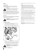
7 Service Flexible Pump Coupler 9. The flexible pump coupler is a nylon “spider” insert, located between the pump and the engine shaft. Over time, the coupler will harden and deteriorate. Replace the coupler if you detect vibration or noise coming from the area between the engine and the pump. If the coupler fails completely, you will experience a loss of hydraulic power. Align the pump coupling half with the nylon “spider” by rotating the engine using the starter handle.
8 Troubleshooting Problem Cylinder rod will not move Slow cylinder shaft speed while extending and retracting Leaking Cylinder 18 Cause Remedy 1. Broken drive shaft. 1. See authorized service dealer. 2. Shipping plugs left in hydraulic hoses. 2. Disconnect hydraulic hoses, remove shipping plugs, reconnect hoses. 3. Set screws in coupling not adjusted properly. 3. See authorized service dealer. 4. Loose shaft coupling. 4. Correct engine/pump alignment as necessary. 5. Gear sections damaged.
Problem Wood will not split or wood splits too slowly Leaking pump shaft seal Cause Remedy 1. Small gear section damaged. 1. See authorized service dealer. 2. Pump check valve leaking. 2. See authorized service dealer. 3. Excessive pump inlet vacuum. 3. Make certain pump inlet hoses are clear and unblocked. 4. Incorrect oil level. 4. Check oil level. 5. Contaminated oil. 5. Drain oil, clean reservoir and refill. 6. Control valve leaking internally. 6. See authorized service dealer. 7.
9 Replacement Parts Component Part Number and Description 737-0348A Vented Dipstick 735-04103 718-04395 718-04392 710-1842A Spider Bushing Coupling, .875 Coupling, .500 Set Screw 723-0405 Hydraulic Oil Filter 737-04308 727-0451 727-04288 727-0443 727-04362 Inlet Filter Inlet Hose Hydro Hose Return Hose Hydro Hose 726-0132 Hose Clamp 634-0187 Wheel, 16.0 x 4.8 x 8.
Notes 10 21
Section 10— Notes
Section 10 — Notes 23
CUB CADET LLC MANUFACTURER’S LIMITED WARRANTY FOR Log Splitters & jet sweeps The limited warranty set forth below is given by Cub Cadet LLC with respect to new merchandise purchased and used in the United States, its possessions and territories, and by MTD Products Limited with respect to new merchandise purchased and used in Canada and/or its territories and possessions. c.