Safe Operation Practices • Set-Up • Operation • Maintenance • Service • Troubleshooting • Warranty Operator’s Manual Hydrostatic Garden Tractor — GT 1054, GTX 1054 WARNING READ AND FOLLOW ALL SAFETY RULES AND INSTRUCTIONS IN THIS MANUAL BEFORE ATTEMPTING TO OPERATE THIS MACHINE. FAILURE TO COMPLY WITH THESE INSTRUCTIONS MAY RESULT IN PERSONAL INJURY. CUB CADET LLC, P.O. BOX 361131 CLEVELAND, OHIO 44136-0019 Printed In USA Form No.
1 To The Owner Thank You Thank you for purchasing a Cub Cadet Garden Tractor. It was carefully engineered to provide excellent performance when properly operated and maintained. If applicable, the power testing information used to establish the power rating of the engine equipped on this machine can be found at www.opei.org or the engine manufacturer’s web site. Please read this entire manual prior to operating the equipment.
Important Safe Operation Practices 2 WARNING! This symbol points out important safety instructions which, if not followed, could endanger the personal safety and/or property of yourself and others. Read and follow all instructions in this manual before attempting to operate this machine. Failure to comply with these instructions may result in personal injury. When you see this symbol.
12. A missing or damaged discharge cover can cause blade contact or thrown object injuries. 13. Stop the blade(s) when crossing gravel drives, walks, or roads and while not cutting grass. 14. Watch for traffic when operating near or crossing roadways. This machine is not intended for use on any public roadway. 15. Do not operate the machine while under the influence of alcohol or drugs. 16. Mow only in daylight or good artificial light. 17. Never carry passengers. 18.
Children Service 1. Safe Handling of Gasoline: Tragic accidents can occur if the operator is not alert to the presence of children. Children are often attracted to the machine and the mowing activity. They do not understand the dangers. Never assume that children will remain where you last saw them. a. Keep children out of the mowing area and in watchful care of a responsible adult other than the operator. b. Be alert and turn machine off if a child enters the area. c.
Periodically check to make sure the blades come to complete stop within approximately (5) five seconds after operating the blade disengagement control. If the blades do not stop within the this time frame, your machine should be serviced professionally by an authorized Cub Cadet Service Dealer. Do not modify engine 4. Check brake operation frequently as it is subjected to wear during normal operation. Adjust and service as required. Notice Regarding Emissions 5.
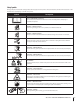
Safety Symbols This page depicts and describes safety symbols that may appear on this product. Read, understand, and follow all instructions on the machine before attempting to assemble and operate. Symbol Description READ THE OPERATOR’S MANUAL(S) Read, understand, and follow all instructions in the manual(s) before attempting to assemble and operate DANGER— ROTATING BLADES Never carry passengers. Never carry children, even with the blades off.
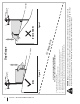
Section 2 — Important Safe Operation Practices Figure 1 line Figure 2 (TOO STEEP) 15° Slope WARNING! Slopes are a major factor related to tip-over and roll-over accidents which can result in severe injury or death. Do not operate machine on slopes in excess of 15 degrees. All slopes require extra caution. If you cannot back up the slope or if you feel uneasy on it, do not mow it. Always mow up and down slopes, never across the face of slopes. To check the slope, proceed as follows: 1.
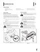
3 Assembly & Set-Up Contents of Crate • One Garden Tractor • One Oil Drain Tube • One Deck Wash Hose Coupler • One Garden Tractor Operator’s Manual • One Engine Operator’s Manual • One Product Registration Card Tractor Set-Up Shipping Brace Removal WARNING! Make sure the garden tractor’s engine is off, set the parking brake and remove the ignition key before removing the shipping brace.
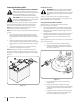
Connecting the Battery Cables Checking Tire Pressure WARNING! Never exceed the maximum inflation pressure shown on the sidewall of the tire. Do not overinflate tires. Check sidewall of tires for maximum psi. Equal tire pressure should be maintained at all times. CALIFORNIA PROPOSITION 65 WARNING! Battery posts, terminals, and related accessories contain lead and lead compounds, chemicals known to the State of California to cause cancer and reproductive harm. Wash hands after handling.
f. Position the deck roller brackets up or down through the slots on the rear of the deck until desired position is reached, then reattach with the clevis pins and hairpin clips just removed. Be certain that the left roller bracket and the right roller bracket are set in the same position. Refer to Leveling the Deck in the Maintenance section of this manual for more detailed instructions regarding various deck adjustments.
4 Controls and Features Systems Indicator Monitor Fuel Tank Cap Ignition Switch Module Throttle/Choke Control Electric PTO Knob Fuel Level Indicator Drive Pedal Brake Pedal Parking Brake/ Cruise Control Lever Reverse Pedal Deck Lift Lever Seat Adjustment Lever Cup Holder Storage Bin Figure 4-1 Garden Tractor controls and features are illustrated in Figure 4-1 and described on the following pages.
Deck Lift Lever Systems Indicator Monitor/Hour Meter LCD Found on your tractor’s right fender, the deck lift lever is used to change the height of the cutting deck. To use, move the lever to the left, then place in the notch best suited for your application.
PTO / Blade Engage Knob Fuel Level Indicator Activating the PTO engages power to the cutting deck or other (separately available) attachments. Pull outward on the PTO/Blade Engage knob to activate it. Push the PTO/ Blade Engage knob inward to disengage the power to the cutting deck or other (separately available) attachments. The Fuel Level Indicator is located on the left side of the tractor’s dash and indicates the amount of fuel in the gas tank.
5 Operation Starting the Engine WARNING! Do not operate the tractor if the interlock system is malfunctioning. This system was designed for your safety and protection. TO AVOID SERIOUS INJURY OR DEATH • • • • • • • • • GO UP AND DOWN SLOPES, NOT ACROSS. AVOID SUDDEN TURNS. DO NOT OPERATE THE UNIT WHERE IT COULD SLIP OR TIP. IF MACHINE STOPS GOING UPHILL, STOP BLADE(S) AND BACK DOWNHILL SLOWLY. KEEP SAFETY DEVICES (GUARDS, SHIELDS, AND SWITCHES, ETC.) IN PLACE AND WORKING.
Driving The Tractor Reverse Caution Mode WARNING! Avoid sudden starts, excessive speed and sudden stops. The REVERSE CAUTION MODE position of the key switch module allows the tractor to be operated in reverse with the blades (PTO) engaged. NOTE: Mowing in reverse is not recommended. 1. Lightly press the brake pedal to release the parking brake. Move the throttle lever into the FAST (rabbit) position. 2.
Driving On Slopes Cruise Control WARNING! Never engage the cruise control lever while traveling in reverse. Refer to the SLOPE GAUGE on page 8 to help determine slopes where you may operate the tractor safely. WARNING! Do not mow on inclines with a slope in excess of 15 degrees (a rise of approximately 2-1⁄2 feet every 10 feet). The tractor could overturn and cause serious injury. To set the cruise control: 1.
Engaging the PTO Mowing WARNING! To help avoid blade contact or a thrown object injury, keep bystanders, helpers, children and pets at least 75 feet from the machine while it is in operation. Stop machine if anyone enters the area. Engaging the PTO transfers power to the cutting deck or other (separately available) attachments. To engage the PTO: 1. Move the throttle control lever to the FAST (rabbit) position. 2. Pull the PTO/Blade Engage knob outward into the engaged (ON) position. See Figure 5-3.
6 Maintenance & Adjustments Maintenance Schedule Before Each use Check Air Filter for Dirty, Loose or Damaged Parts Every 25 Hours Every 50 Hours Every 100 Hours P Clean Hood/Dash Louvers Check Engine Oil Level Every 10 Hours Prior to Storing P P P P Clean and Re-oil Air Filter’s Foam Pre-Cleaner P Replace Air Filter Element P Change Engine Oil and Replace Oil Filter Clean Battery Terminals P P P P P Lube Front Axles and Rims Clean Engine Cooling Fins Lube Front Deck Wheels Lube Deck Spind
3. Pop open the protective cap on the end of the oil drain valve to expose the drain port. See Figure 6-1. 4. Remove the oil fill cap/dipstick from the oil fill tube. 5. Push the oil drain hose (packed with this manual) onto the oil drain port. Route the opposite end of the hose into an appropriate oil collection container with at least a 2.5 quart capacity, to collect the used oil. 6. The engine is equipped with either a twist-and-pull drain port or a tabbed drain port.
3. Attach the hose coupler to the water port on your deck’s surface. See Figure 6-2. 4. Turn the water on. 5. While sitting in the operator’s position on the tractor, start the engine and place the throttle lever in the FAST (rabbit) position. 6. Move the tractor’s PTO (Blade Engage) into the ON position. 7. Remain in the operator’s position with the cutting deck engaged for a minimum of two minutes, allowing the underside of the cutting deck to thoroughly rinse. 8.
Adjustments WARNING! Shut the engine off, remove the ignition key and engage the parking brake before making adjustments. Protect your hands by using heavy gloves when handling the blades. NOTE: Check the tractor’s tire pressure before performing any deck leveling adjustments. Refer to Tires on page 28 for information regarding tire pressure. Leveling the Deck (Front To Rear) Determine the approximate distance necessary for proper adjustment and proceed, if necessary. 1.
Leveling the Deck (Side to Side) Steering Adjustment If the cutting deck appears to be mowing unevenly, a side to side adjustment can be performed. Adjust if necessary as follows: If the tractor turns tighter in one direction than the other, or if the ball joints are being replaced due to damage or wear, the steering drag links may need to be adjusted. 1.
Deck Rear Roller Adjustment (If Equipped) The rear rollers on the mower deck are not designed to carry the weight of the deck. The rear rollers should be adjusted to approximately 1⁄4” to 1⁄2” above the ground when the deck is moved to the desired cutting height. Place the tractor on a smooth, flat surface, move the deck to the desired cutting height, and check the height of the rear rollers.
7 Service Cutting Deck Removal NOTE: If there is too much tension on the belt for it to be easily removed from the electric PTO clutch, carefully insert a 3⁄8” drive ratchet wrench (set to loosen) into the square hole found in the left-hand deck idler bracket and pivot it toward the tractor’s right side to relieve tension on the belt. See Figure 7-2. To remove the cutting deck, proceed as follows: 1. Place the PTO/Blade Engage knob in the disengaged (OFF) position and engage the parking brake. 2.
6. Pull the deck support pin outward to release the deck from the deck lift arm. See Figure 7-3. Cutting Blades WARNING! Shut the engine off and remove ignition key before removing the cutting blade(s) for sharpening or replacement. Protect your hands by using heavy gloves when grasping the blade WARNING! Periodically inspect the blade and/or spindle for cracks or damage, especially after you’ve struck a foreign object. Do not operate the machine until damaged components are replaced.
Battery CALIFORNIA PROPOSITION 65 WARNING! Battery posts, terminals, and related accessories contain lead and lead compounds, chemicals known to the State of California to cause cancer and reproductive harm. Wash hands after handling. CAUTION: If removing the battery, disconnect the NEGATIVE (Black) wire from it’s terminal first, followed by the POSITIVE (Red) wire. When reinstalling the battery, always connect the POSITIVE (Red) wire its terminal first, followed by the NEGATIVE (Black) wire.
Fuse 4. WARNING! Before servicing, repairing, or inspecting, always disengage PTO, set parking brake, stop engine and remove key to prevent unintended starting. A fuse is installed in your tractor’s wiring harness to protect the tractor’s electrical system from damage caused by excessive amperage. Remove the deck belt from around the three spindle pulleys and the two deck idler pulleys. NOTE: The idler pulleys may have to be loosened, but not removed, in order to remove the belt from around them. 5.
10. Pull the right side of the belt and place the narrow V side of the belt into the PTO pulley. See Figure 7-9. 11. While holding the belt and pulley together, rotate the pulley to the left (See Figure 7-9). Continue holding and rotating the pulley and belt until the belt is fully rolled into the PTO pulley. Deck Idler Pulleys Changing the Transmission Drive Belt Several components must be removed and special tools used in order to change the tractor’s transmission drive belt.
8 Troubleshooting Problem Engine fails to start Remedy 1. PTO/Blade Engage knob engaged. 1. Place knob in disengaged (OFF) position. 2. Parking brake not engaged. 2. Engage parking brake. 3. Spark plug wire(s) disconnected. 3. Connect wire(s) to spark plug(s). 4. Throttle/choke control lever not in correct starting position. 4. Place throttle/choke lever into the CHOKE position. 5. Fuel tank empty, or stale fuel. 5. Fill tank with clean, fresh (less than 30 days old) gas. 6. Blocked fuel line.
9 Replacement Parts Component Part Number and Description 759-3336 Spark Plug KH-32-883-03-S1 Kohler Air Filter Element & Pre-Cleaner KH-52-050-02-S Kohler Oil Filter KH-25-050-22-S1 Kohler Fuel Filter 954-04083 Drive Belt (Mowing Deck) 942-0677B 2-in-1 Deck Blade 918-04608A Deck Spindle Phone (800) 965-4CUB to order replacement parts or a complete Parts Manual (have your full model number and serial number ready). Parts Manual downloads are also available free of charge at www.cubcadet.com.
Component Part Number and Description 734-04155 Deck Wheel 925-1707D Battery 951-12179B Fuel Tank Cap 946-04556 Throttle/Choke Control Cable 925-2054A Ignition Key 631-04070A Discharge Chute Assembly Phone (800) 965-4CUB to order replacement parts or a complete Parts Manual (have your full model number and serial number ready). Parts Manual downloads are also available free of charge at www.cubcadet.
10 Attachments & Accessories The following attachments and accessories are compatible for Cub Cadet GT 1054 and GTX 1054. See your Cub Cadet dealer or the retailer from which you purchased your tractor for information regarding price and availability. Model Number Description 190-841-191 Mulch Kit 19A40002101 Bagger STANDARD Bumper Kit OEM-190-833 Dozer Blade OEM-190-032 42-Inch Two Stage Snow Thrower 490-900-M060 42 Ib. Rear Suit Case Weight Kit With Bracket 490-900-M059 42 lb.
FEDERAL and/or CALIFORNIA EMISSION CONTROL WARRANTY STATEMENT YOUR WARRANTY RIGHTS AND OBLIGATIONS MTD Consumer Group Inc, the United States Environmental Protection Agency (EPA), and, for those products certified for sale in the state of California, the California Air Resources Board (CARB) are pleased to explain the emission (evaporative and/or exhaust) control system (ECS) warranty on your outdoor 2006 and later small off-road spark-ignited engine and equipment (outdoor equipment engine) In California, n
10. Add-on or modified parts that are not exempted by the Air Resources Board may not be used. The use of any non-exempted add-on or modified parts by the ultimate purchaser will be grounds for disallowing a warranty claims. MTD Consumer Group Inc will not be liable to warrant failures of warranted parts caused by the use of a non-exempted add-on or modified part.
CUB CADET LLC MANUFACTURER’S LIMITED WARRANTY FOR SERIES 1000 & SERIES 1500 TRACTORS IMPORTANT: To obtain warranty coverage owner must present an original proof of purchase and applicable maintenance records to the servicing dealer. Please see the operator’s manual for information on required maintenance and service intervals.