Safe Operation Practices • Set-Up • Operation • Maintenance • Service • Troubleshooting • Warranty Operator’s Manual GT 2042, GT 2148, GT 2050, GTX 2154 WARNING READ AND FOLLOW ALL SAFETY RULES AND INSTRUCTIONS IN THIS MANUAL BEFORE ATTEMPTING TO OPERATE THIS MACHINE. FAILURE TO COMPLY WITH THESE INSTRUCTIONS MAY RESULT IN PERSONAL INJURY. CUB CADET LLC, P.O. BOX 361131 CLEVELAND, OHIO 44136-0019 Printed In USA Form No.
1 To The Owner Thank You Thank you for purchasing a Cub Cadet Garden Tractor. It was carefully engineered to provide excellent performance when properly operated and maintained. If applicable, the power testing information used to establish the power rating of the engine equipped on this machine can be found at www.opei.org or the engine manufacturer’s web site. Please read this entire manual prior to operating the equipment.
Important Safe Operation Practices 2 WARNING! This symbol points out important safety instructions which, if not followed, could endanger the personal safety and/or property of yourself and others. Read and follow all instructions in this manual before attempting to operate this machine. Failure to comply with these instructions may result in personal injury. When you see this symbol.
12. A missing or damaged discharge cover can cause blade contact or thrown object injuries. 13. Stop the blade(s) when crossing gravel drives, walks, or roads and while not cutting grass. 14. Watch for traffic when operating near or crossing roadways. This machine is not intended for use on any public roadway. 15. Do not operate the machine while under the influence of alcohol or drugs. 16. Mow only in daylight or good artificial light. 17. Never carry passengers. 18.
Children Service 1. Safe Handling of Gasoline: Tragic accidents can occur if the operator is not alert to the presence of children. Children are often attracted to the machine and the mowing activity. They do not understand the dangers. Never assume that children will remain where you last saw them. a. Keep children out of the mowing area and in watchful care of a responsible adult other than the operator. b. Be alert and turn machine off if a child enters the area. c.
Periodically check to make sure the blades come to complete stop within approximately (5) five seconds after operating the blade disengagement control. If the blades do not stop within the this time frame, your machine should be serviced professionally by an authorized Cub Cadet Service Dealer. Do not modify engine 4. Check brake operation frequently as it is subjected to wear during normal operation. Adjust and service as required. Notice Regarding Emissions 5.
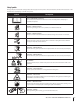
Safety Symbols This page depicts and describes safety symbols that may appear on this product. Read, understand, and follow all instructions on the machine before attempting to assemble and operate. Symbol Description READ THE OPERATOR’S MANUAL(S) Read, understand, and follow all instructions in the manual(s) before attempting to assemble and operate DANGER— ROTATING BLADES Never carry passengers. Never carry children, even with the blades off.
Section 2 — Important Safe Operation Practices Figure 1 line Figure 2 (TOO STEEP) 15° Slope WARNING! Slopes are a major factor related to tip-over and roll-over accidents which can result in severe injury or death. Do not operate machine on slopes in excess of 15 degrees. All slopes require extra caution. If you cannot back up the slope or if you feel uneasy on it, do not mow it. Always mow up and down slopes, never across the face of slopes. To check the slope, proceed as follows: 1.
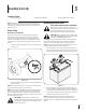
3 Assembly & Set-Up Contents of Crate • One Garden Tractor • One Operator’s Manual NOTE: This Operator’s Manual covers several models. Tractor features may vary by model. Not all features in this manual are applicable to all tractor models and the tractor depicted may differ from yours. CALIFORNIA PROPOSITION 65 WARNING! Battery posts, terminals, and related accessories contain lead and lead compounds, chemicals known to the State of California to cause cancer and reproductive harm.
Lower Deck Discharge Chute Deflector Adjusting the Seat The discharge chute deflector must be installed before operating the mower. To adjust the position of the seat, push the seat adjustment lever to the left. Slide the seat forward or rearward to the desired position; then release the adjustment lever. Make sure seat is locked into position before operating the tractor. See Figure 3-5. 1. Remove the keys that are attached with a zip tie to the chute bracket. 2.
4 Controls & Features Choke Control LCD Service Minder & Hour Meter Cruise Control/ Parking Brake Lever PTO/Blade Engage Lever Throttle Control Ignition Switch Module Forward Drive Pedal Brake Pedal Steering Tilt Lever Reverse Drive Pedal Electric Lift Switch Cup Holder Storage Compartment Fuel Cap Manual Lift Handle Cutting Height Lever Low Gas Window Hydrostatic Transmission Dipstick/Fill Tube NOTE: This Operator’s Manual covers several models. Tractor features may vary by model.
Manual Lift Lever (If so equipped) LO 3 2 4 7 6 5 Forward Drive Pedal 8 9 HI The lift lever is located in the right fender and is used to raise and lower the deck. Pull the handle to the left out of the index notch and push downward to lower the deck, or pull upward to raise the deck. When the desired height is attained, move the lift handle to the right until fully in the index notch.
Low Gas Window LCD Service Minder & Hour Meter The low gas window is located at the rear of the tractor. If the gas level is visible in this window, the tank should be re-filled. When the ignition key is rotated out of the STOP position but not into the START position, the LCD Service Minder and Hour Meter will briefly disply the battery voltage, followed by the tractor’s accumulated hours.
5 Operation WARNING! Avoid serious injury or death. Go up and down slopes, not across. Avoid sudden turns. Do not operate unit where it could slip or tip. If machine stops going uphill, stop PTO and back down the hill safely. Keep safety devices (guards, shields and switches) in place and working. Remove objects that could be thrown by the blades. Know location and function of all controls. Be sure the blades and the engine are stopped before placing hands or feet near blades.
Reverse Caution Mode Driving The Tractor WARNING! Avoid sudden starts, excessive speed and sudden stops. The REVERSE CAUTION MODE position of the key switch module allows the tractor to be operated in reverse with the blades (PTO) engaged. NOTE: Mowing in reverse is not recommended. WARNING! Use extreme caution while operating the tractor in the REVERSE CAUTION MODE . Always look down and behind before and while backing. Do not operate the tractor when children or others are around.
Driving On Slopes Setting The Cruise Control WARNING! Never engage the cruise control lever while traveling in reverse. Refer to the SLOPE GAUGE on page 8 to help determine slopes where you may operate the tractor safely. WARNING! Do not mow on inclines with a slope in excess of 15 degrees (a rise of approximately 2-1⁄2 feet every 10 feet). The tractor could overturn and cause serious injury. 1. Exercise extreme caution when changing direction on slopes.
Operating the Headlights Mowing WARNING! Make certain the area to be mowed is free of debris, sticks, stones, wire or other objects that can be thrown by the rotating blades. The lamps are ON whenever the ignition key is rotated out of the STOP position. The lamps turn OFF when the ignition key is moved to the STOP position. Engaging the PTO Engaging the PTO transfers power to the cutting deck or other (separately available) attachments. To engage the PTO: 1.
6 Maintenance & Adjustments Maintenance Schedule Before Each use Check/Clean Engine Intake Screen Every 10 Hours Check Transmission Oil Every 200 Hours P Prior to Storing P P P Clean Hood/Dash Louvers Check Engine Oil Level Every 25 Hours P P P Change Transmission Oil & Filter * P Clean Battery Terminals P P Lube Front Axles and Rims Lube Pedal Pivot Points P P P * — For break-in operation, change after the first 50 hours of use and then every 200 hours thereafter.
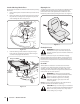
4. While holding the free end of the oil drain hose over the oil collection container, unscrew the square head hose plug from the end of the hose. See Figure 6-1. Drain the engine oil into the collection container. Hydrostatic Transmission Oil Checking the Hydrostatic Transmission Oil The dipstick to check the hydrostatic transmission oil level is located on the back of the mower on the upper section of the frame. Refer to the Controls & Features section of this manual. 1.
3. Remove the drain plug and allow the transmission oil to drain into a clean container having a capacity of more than six quarts. Reinstall the drain plug. See Figure 6-3. Cleaning the Tractor Any fuel or oil spilled on the machine should be wiped off promptly. Do NOT allow debris to accumulate around the cooling fins of the engine, the transmission’s cooling fan or on any other part of the machine.
Lubrication Smart Jet Your tractor’s deck is equipped with a water port on its surface as part of its deck wash system. Use the Smart Jet to rinse grass clippings from the deck’s underside and prevent the buildup of corrosive chemicals. Complete the following steps AFTER EACH MOWING: 1. Drive the tractor to a level, clear spot on your lawn, near enough for your garden hose to reach. CAUTION: Make certain the tractor’s discharge chute is directed AWAY from your house, garage, parked cars, etc. 1.
Adjustments Leveling the Deck (Side to Side) WARNING! Shut the engine off, remove the ignition key and engage the parking brake before making adjustments. Protect your hands by using heavy gloves when handling the blades. NOTE: Check the tractor’s tire pressure before performing any deck leveling adjustments. Refer to Tires on page 10 for information regarding tire pressure. If the cutting deck appears to be mowing unevenly, a side to side adjustment can be performed. Adjust if necessary as follows: 1.
Wheel Alignment Steering/Toe-in Adjustment The front wheels should toe-in approximately 1⁄8 to 1⁄4”, as measured across dimensions A and B. See Figure 6-9. To adjust front wheel toe-in, proceed as follows: 1. Steering Gear Centered Pivot Hole Centering Hole NOTE: A 5⁄16” pin can be used in the alignment holes to assure the steering segment is centered. 2. Mark the front horizontal diameter of both front wheels at the same spot on each wheel-preferably the inner bead flange of the wheel rims.
Pivot Bar Adjustment CAUTION: The tractor should be checked every 50 hours of operation for play between the frame channel and the pivot bar. Check and adjust the pivot axle as follows: 1. Raise the front of the tractor and set it on jack stands, so the front wheels are suspended above the ground. WARNING! When jacking up the front end of the tractor, always chock the rear wheels to prevent the tractor from rolling, tipping or sliding off the jack stands. 2.
7 Service Battery 3. Common Causes For Battery Failure Note which battery tray hole the RH side of the hold-down rod is hooked into. 4. Rotate the hold-down rod upward, over and around the battery to unhook from the battery tray. 5. Lift the battery out off the battery tray and remove from the tractor. 1. Overcharging 2. Undercharging 3. Loose and/or corroded connections 4. Excessive loads 6. Position the new battery and lower into the battery tray. 5. Freezing of electrolyte 7.
Headlights Cutting Deck Removal Refer to Replacement Parts section when replacement of head lamp bulbs is necessary. To remove the cutting deck, proceed as follows: Replace headlight bulbs as follows: 1. Fully raise the hood of the tractor. 2. Unplug the wire harness leads from the headlight socket terminals. Note which wire connects to each terminal before disconnecting. 3. 1.
5. Carefully remove the PTO belt around the deck drive pulley, 6. Feed the belt forward and remove it from around the mule drive pulleys and the tractor’s PTO clutch pulley. 7. Looking at the cutting deck from the left side of the tractor, locate the deck support pin on the rear left side of the deck. 8. Pull the deck support pin outward to release the deck from the deck lift arm. See Figure 7-5.
4. To properly sharpen the cutting blades, remove equal amounts of metal from both ends of the blades along the cutting edges, parallel to the trailing edge, at a 25°- to 30° angle. Always grind each cutting blade edge equally to maintain proper blade balance. See Figure 7-7. Changing the Deck Belt WARNING! The V-belts found on your tractor are specially designed to engage and disengage safely. A substitute (non-OEM) V-belt can be dangerous by not disengaging completely.
42” Deck 48: Deck Section 7 — Service 29
50” Deck 54” Deck 30 Section 7— Service
8 Troubleshooting Problem Excessive vibration Mower will not mulch grass (If equipped) Uneven cut Cause Remedy 1. Cutting blade loose or unbalanced. 1. Tighten blade and spindle. 2. Damaged or bent cutting blade. 2. Replace blade. 1. Engine speed too low. 1. Place throttle in FAST (rabbit) position. 2. Wet grass. 2. Do not mulch when grass is wet. 3. Excessively high grass. 3. Mow once at a high cutting height, then mow again at desired height or make a narrower cutting swath. 4. Dull blade.
9 Replacement Parts Component Part Number and Description 759-3336 Spark Plug KH-52-050-02-S1 Oil Filter KH-24-050-13-S Fuel Filter KH-47-883-03-S1 Fuel Filter 954-0645A 754-04045 954-04118 Deck Belt, 42” Deck Deck Belt, 48” Deck Deck Belt, 50 & 54” Deck 954-04055 PTO Belt 942-04374 942-04417 02005017-X 742-04047 942-04416 02005018-X 21” Blade, 42” Deck 17” Blade, 48” Deck 17” Xtreme Blade, 48” Deck 18” Blade, 50” Deck 19” Blade, 54” Deck 19” Xtreme Blade, 54” Deck 618-3129C0 Spindle Assembly
Component Part Number and Description 951-12725 Fuel Cap 946-04759A Choke Control Cable 946-04771A Throttle Control Cable 925-05000 Ignition Key 925-0963 12V Bulb 734-04155 Deck Wheel Phone (800) 965-4CUB to order replacement parts or a complete Parts Manual (have your full model number and serial number ready). Parts Manual downloads are also available free of charge at www.cubcadet.com.
10 Attachments & Accessories 34 Part No. Part 19A40003100 19A40004100 42” Bagger 48/50/54” Bagger 19A40021100 19A70016100 190-193-100 19A70023100 42” Mulch Kit 48” Mulch Kit 50” Mulch Kit 54” Mulch Kit 19A40022100 Dozer Blade 19A40020100 Snow Thrower 490-241-0026 Tire Chains 190-307-100 Weight Kit 490-900-M059 Extra Weight 490-290-0013 Riding Mower Cover 490-850-0008 Oil Siphon 490-850-0005 Blade Removal Tool 490-325-0020 Tire Sealant 490-900-0045 Oil Filter Wrench 22216 32 oz.
Notes 11 35
Section 11— Notes
Section 11 — Notes 37
FEDERAL and/or CALIFORNIA EMISSION CONTROL WARRANTY STATEMENT YOUR WARRANTY RIGHTS AND OBLIGATIONS MTD Consumer Group Inc, the United States Environmental Protection Agency (EPA), and for those products certified for sale in the state of California, the California Air Resources Board (CARB) are pleased to explain the evaporative emission control system (ECS) warranty on your 2013-2014 small off-road equipment (outdoor equipment).
WARRANTED PARTS: The repair or replacement of any warranted part otherwise eligible for warranty coverage may be excluded from such warranty coverage if MTD Consumer Group Inc demonstrates that the outdoor equipment has been abused, neglected, or improperly maintained, and that such abuse, neglect, or improper maintenance was the direct cause of the need for repair or replacement of the part.
CUB CADET LLC MANUFACTURER’S LIMITED WARRANTY FOR SERIES 2000 TRACTORS IMPORTANT: To obtain warranty coverage owner must present an original proof of purchase and applicable maintenance records to the servicing dealer. Please see the operator’s manual for information on required maintenance and service intervals. In the U.S.A. Check your Yellow Pages, or contact Cub Cadet LLC at P.O. Box 361131, Cleveland, Ohio 44136-0019, call 1-877-282- 8684 or log on to our website at www.cubcadet.com.