
User Manual

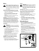
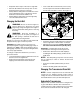


Table Of Contents
- SECTION 1: important safe operation practices
- SECTION 2: slope gauge
- SECTION 3: tractor set-up
- Gas and Oil Fill-up
- Setting the Gauge Wheels and Roller
- SECTION 4: know your lawn tractor
- Throttle Control Lever
- Choke Control
- Brake Pedal
- Seat Adjustment Lever
- Ignition Switch Module
- Drive Pedal
- Systems Indicator Monitor / Hour Meter
- Deck Lift Lever
- Electric PTO / Blade Engage Knob
- Cruise Control Lever
- Parking Brake Lever
- SECTION 5: operating your lawn tractor
- Safety Interlock Switches
- Reverse Caution Mode
- Starting the Engine
- Stopping the Engine
- Engaging the Parking Brake
- Driving The Tractor
- Driving On Slopes
- Setting The Cruise Control
- Using the Deck Lift Lever
- Operating the Headlights
- Moving The Tractor Manually
- Engaging the PTO
- Mowing
- SECTION 6: making adjustments
- Leveling the Deck
- Parking Brake Adjustment
- Seat Adjustment
- Steering Adjustment
- SECTION 7: maintaining your lawn tractor
- Engine
- Changing the Engine OIl
- Air Filter
- Cleaning the Engine And Deck
- Lubrication
- Carburetor
- SECTION 8: service
- Tires
- Fuse
- Cutting Blades
- Battery
- Cutting Deck Removal
- Changing the Deck Belt
- Changing The Transmission Drive Belt
- Hydrostatic Transmission
- SECTION 9: off-season storage
- Engine
- SECTION 10: maintenance chart
- SECTION 11: maintenance log
- SECTION 12: troubleshooting
- SECTION 13: attachments & accessories
- SECTION 14: Replacement Parts
- SECTION 15: specifications*
24
SECTION 8: SERVICE
Tires
WARNING: Never exceed the maximum
inflation pressure shown on the sidewall of the
tire.
The recommended operating tire pressure is
approximately 10 psi for the rear tires and 14 psi for the
front tires.
Refer to the tire sidewall for exact tire manufacturer’s
recommended or maximum psi. Do not overinflate.
Uneven tire pressure could cause the cutting deck to
mow unevenly.
Fuse
A fuse is installed in your tractor’s wiring harness to
protect the tractor’s electrical system from damage
caused by excessive amperage.
If the electrical system does not function, or your
tractor’s engine will not crank, first check to be certain
that the fuse has not blown.
It can be found under the hood mounted behind the top
of the dash panel on the support bar.
IMPORTANT:
Always use a fuse with the same
amperage capacity for replacement.
WARNING: Before servicing, repairing, or
inspecting, always disengage PTO, set
parking brake, stop engine and remove key to
prevent unintended starting.
Cutting Blades
WARNING: Be sure to shut the engine off,
remove ignition key and disconnect the spark
plug wire(s) to prevent unintended starting
before removing the cutting blade(s) for
sharpening or replacement. Always Protect
your hands by using heavy gloves when
grasping the blade.
WARNING: Periodically inspect the blade
adapter and/or spindle for cracks or damage,
especially if you strike a foreign object.
Replace immediately if damaged
.
The blades may be removed as follows.
• Remove the deck from beneath the tractor (refer to
Cutting Deck Removal on page 26), then gently flip the
deck over to expose its underside.
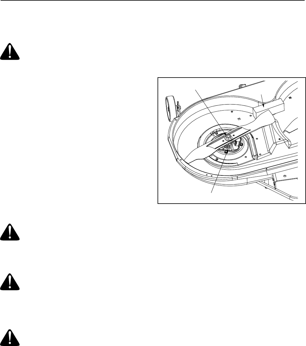
• Place a block of wood between the center deck
housing baffle and the cutting blade to act as a
stabilizer. See Figure 17.
Figure 17
• Remove the hex flange nut that secures the blade
to the spindle assembly. See Figure 17.
IMPORTANT:
To properly sharpen the cutting blades,
remove equal amounts of metal from both ends of the
blades along the cutting edges, parallel to the trailing
edge, at a 25° to 30° angle.
IMPORTANT:
If the cutting edge of the blade has already
been sharpened, or if any metal separation is present,
replace the blades with new ones.
It is important that each cutting blade edge be ground
equally to maintain proper blade balance. A poorly
balanced blade will cause excessive vibration and may
cause damage to the tractor and result in personal
injury.
IMPORTANT:
When replacing the blade, be sure to
install the blade with the side of the blade marked
‘‘Bottom’’ (or with a part number stamped in it) facing
the ground when the mower is in the operating position.
IMPORTANT:
Use a torque wrench to tighten the blade
spindle hex flange nut to between 70 lbs-ft and 90 lbs-ft.
Spindle Assembly
Hex Flange Nut
Wood Block