OPERATOR’S MANUAL SERIES 2500 TRACTOR Model Number GT 2544 IMPORTANT: READ SAFETY RULES AND INSTRUCTIONS CAREFULLY Warning: This unit is equipped with an internal combustion engine and should not be used on or near any unimproved forestcovered, brush-covered or grass-covered land unless the engine’s exhaust system is equipped with a spark arrester meeting applicable local or state laws (if any). If a spark arrester is used, it should be maintained in effective working order by the operator.
TABLE OF CONTENTS Section I II III IV V VI VII Page Tractor and Deck Preparation ............. Safe Operation Practices..................... Product Graphics................................. Slope Gauge ....................................... To The Owner...................................... Calling Service Information.................. Recording Model & Serial Number ...... Know Your Tractor .............................. Operation............................................. Adjustments................
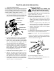
TRACTOR AND DECK PREPARATION 2. CONNECT THE BATTERY 1. TRACTOR STEERING WHEEL For shipping purposes, the steering wheel was removed from the steering shaft. Pivot the seat rearward and remove any packaging material from the seat. Cut the ties securing the steering wheel and remove any packaging material. Install the steering wheel as follows: 1. Locate the steering bellow and note the riser at one end of the bellow. With the riser facing upward, slide the bellow onto the steering shaft. See Figure 1.
WARNING • The engine exhaust, some of its constituents, and certain vehicle components contain or emit chemicals known to the State of California to cause cancer, birth defects or other reproductive harm. • This unit is equipped with an internal combustion engine and should not be used on or near any unimproved forest-covered, brush-covered, or grass-covered land unless the engine’s exhaust system is equipped with a spark arrester meeting applicable local or state laws (if any).
DO: 1. Mow up and down slopes, not across. Exercise extreme caution when changing directions on slopes. 2. Remove obstacles such as rocks, limbs, etc. Watch for holes, ruts or bumps. Uneven terrain could overturn the machine. Tall grass can hide obstacles. 3. Use slow speed. Choose a low enough speed setting so that you will not have to stop or shift while on the slope. Tires may lose traction on slopes even though the brakes are functioning properly.
ground. If this is not possible, then refuel such equipment on a trailer with a portable container, rather than from a gasoline dispenser nozzle. 3. Before and when backing up, look behind and down for small children. 4. Never carry children, even with the blades off. Children may fall off and be seriously injured or may interfere with safe machine operation. 5.
10. Never attempt to make adjustments or repairs to the machine while the engine is running. 5. Check the blade(s) and engine mounting bolts at frequent intervals for proper tightness. Also, visually inspect blade(s) for damage (e.g., excessive wear, bent, cracked). Replace the blades with the original equipment manufacturer’s blades only. “Use of parts which do not meet the original equipment specifications may lead to improper performance and compromise safety!” 11.
PRODUCT GRAPHICS Keep product safety graphics (decals) clean. Replace any safety graphic that is damaged, destroyed, miss- ing, painted over or can no longer be read. Replacement safety graphics are available through your dealer. STARTING INSTRUCTIONS 1. BE FAMILIAR WITH CONTROLS BEFORE STARTING ENGINE AND OPERATING. 2. SET CHOKE, MOVE THROTTLE TO MID POSITION AND DEPRESS BRAKE PEDAL. 3. TURN KEY TO THE START POSITION. 4. AFTER ENGINE STARTS OPEN CHOKE. STOPPING INSTRUCTIONS 1.
SLOPE GAUGE , RE PRE S E NTIN G A1 5 ° S LOP E OR A FENCE POST A CORNER OF A BUILDING A POWER POLE SIGHT AND HOLD THIS LEVEL WITH A VERTICAL TREE USE THIS PAGE AS A GUIDE TO DETERMINE SLOPES WHERE YOU MAY NOT OPERATE SAFELY. FOL D ON D OT T E D LIN E 15° WARNING Do not mow on inclines with a slope in excess of 15 degrees (a rise of approximately 2-1/2 feet every 10 feet). A riding mower could overturn and cause serious injury.
TO THE OWNER This Operator’s Manual is an important part of your new tractor. The information contained in this manual has been prepared in detail to help you better understand the features, correct operation, adjustments, and maintenance of your tractor. The performance and dependability of this tractor rely greatly on the manner in which it is operated and maintained. Therefore, it is recommended that all operators of the tractor carefully read this manual and fully understand its operation.
SECTION I. KNOW YOUR TRACTOR B C A H E I F D M G J K L O Q Q N P A. B. C. D. E. F. G. H. I. Hour Meter/Battery Display Indicator Panel/Hour Meter Key Switch Module Power Take-Off (PTO) Control Switch Throttle Control Lever Choke Control Parking Brake/Cruise Lever Brake Pedal Forward Control Pedal J. K. L. M. N. O. P. Q.
A. HOUR METER/BATTERY DISPLAY The hour meter records and digitally displays the hours that the tractor has been operated (tenths of an hour-right most digit). NOTE: The hour meter is activated whenever the ignition switch is turned to an ‘On’ position. Keep a record of the actual hours of operation to assure all maintenance procedures are completed according to the instructions in this manual.
WARNING: To prevent accidental starting and/or battery discharge, remove the key from the key switch when the tractor is not in use. REVERSE PUSH BUTTON — The orange/triangular button at the top/right corner of the key switch module activates the system that allows the tractor’s blades (PTO) to remain engaged when the tractor is driven in the reverse direction.
The safety interlock system will automatically shut off the engine if the operator leaves the seat with the PTO in the “RUN” position, regardless of whether the brake lock is engaged. The PTO switch must be moved to the “OFF” position to restart the engine. L. LIFT HANDLE The lift handle is located in the left fender and is used to raise and lower equipment used with the tractor.
SECTION II. OPERATION NOTE: Purchase gasoline in small quantities. Do not use gasoline left over from the previous season, to minimize gum deposits in the fuel system. WARNING: Before you operate the tractor, study this manual carefully. Familiarize yourself with the operations of all the instruments and controls. Learn to operate this machine safely. Don’t risk INJURY or DEATH. Gasohol (up to 10% ethyl alcohol, 90% unleaded gasoline by volume) is an approved fuel.
COLD WEATHER STARTING HINTS STARTING THE ENGINE WARNING: Engine exhaust gases are dangerous. Do not run the engine in a confined area such as a storage building any longer than is necessary. Immediately move the tractor outdoors. WARNING: For personal safety, the operator must be sitting in the tractor seat when starting the engine. Never try to start the engine while standing on the ground. 1.
5. Disengage the cruise control using one of the following methods: DRIVING THE TRACTOR NOTE: Avoid sudden starts, excessive speed and sudden stops. WARNING: Do not leave the seat of the tractor without disengaging the PTO and engaging the parking brake. If leaving the tractor unattended, turn the ignition key off and remove the key. IMPORTANT: When using PTO driven equipment, the throttle lever should be in the “FAST” position.
Operate the PTO clutch as follows: STOPPING THE TRACTOR • WARNING: Always engage the brake pedal lock, push the PTO switch to the “OFF” position, lower the equipment and shut off the engine before dismounting. 1. Move the throttle control lever to approximately the mid throttle position. Fully depress the brake pedal to bring the tractor to a complete stop (and disengage the cruise control).
MODE” (Yellow) position of the key switch module. Refer to Figure 11. USING THE “REVERSE CAUTION MODE” KEY POSITION NOTE: Mowing in reverse is not recommended. The “REVERSE CAUTION MODE” position of the key switch module allows the machine to be operated in reverse with the blades (PTO) engaged. To utilize, proceed as follows: WARNING: Use extreme caution while operating the tractor in the “REVERSE CAUTION MODE”. Always look down and behind before and while backing.
SECTION III. ADJUSTMENTS This section contains information for the various adjustments on the tractor. Adjustment information for the mower deck is located in Section V – Mower Deck. ADJUSTING THE SEAT WARNING: Do not adjust the seat when the tractor is moving. Adjusting the seat while the tractor is moving could cause the operator to lose control of the tractor. Both seat arm rests can be rotated upward for mounting and dismounting the tractor, or for the personal comfort of the operator.
WHEEL ALIGNMENT The front wheels should toe-in approximately 1/8 to 1/4 inch, as measured across dimensions A and B shown in Figure 14. Viewed from beneath the tractor 4. Loosen the jam nuts from the ball joints (See Figure 15). 5. Disconnect the front ball joints from the steering arms by removing the hex lock nuts (Refer to Figure 15). Manually move each wheel to achieve the required toe-in and equal D measurements.
2. Raise the rear of the tractor, so that the rear tires are at least one inch above the surface, and set it on jack stands. Make certain the jack stands are positioned to balance the tractor and prevent tipping. PIVOT AXLE ADJUSTMENT BOLTS WARNING: The operator presence safety circuit will stop the engine if the seat is empty when the brake pedal is released. If an assistant is seated when adjusting the neutral setting, use extreme caution to prevent the tractor from tipping or rolling.
3 10 2 4 CONTROL CAM 5 1 6 7 9 1. 2. 3. 4. 5. 6. 7. 8. 9. 10. Front Control Rod Rear Control Rod Hex Tap Screw Hex Wash Hd Tapp Screw Control Arm Control Arm Pin Neutral Arm Centering Pin Neutral Return Adjust. Brkt.
CARBURETOR ADJUSTMENTS WARNING: When making adjustments to the carburetor while the engine is running, disengage the PTO clutch and engage the brake pedal lock. Keep clear of all moving parts and be careful of all hot surfaces. WARNING: Carbon monoxide fumes can be fatal! Do not make any adjustments to the carburetor in a confined area such as a storage building. Move the tractor outside into the open air. NOTE: Carburetor adjustments should be made only after the engine has warmed up. 1.
SECTION IV. MAINTENANCE ENGINE MAINTENANCE • Maintenance, repair, or replacement of the emission control devices and systems, which are being done at the customer’s expense, may be performed by any engine repair establishment or individual. Warranty repairs must be performed by an authorized Kohler service outlet. • ENGINE OIL The engine-crankcase is filled with 10W-30 ship-away oil at the factory. This oil may be used for the first 25 hours of engine operation at temperatures between 0°F and 80°F.
NOTE: For best results, fill to the “FULL” mark on the dipstick as opposed to adding a given quantity of oil. Always check the level on the dipstick before adding more oil. Refer to the LUBRICATION TABLE for information regarding the proper type of oil to add to the crankcase. 1. Place the tractor on a level surface and engage the brake pedal lock. Stop the tractor engine and remove the ignition key. 2.
10. Apply a light coating of clean oil on the gasket of the new oil filter. Thread the filter on by hand until the gasket contacts the oil filter adapter, then tighten the filter an additional 2/3 to 1 turn. Refer to the LUBRICATION TABLE and follow the instruction in the following sub-section to refill the crankcase with the quantity and type of oil specified. FILLING THE CRANKCASE WARNING: Never overfill the engine crankcase.
3. Remove the oil fill plug/dipstick from the oil fill port and SLOWLY pour oil into the oil fill port. Fill the transmission case until the oil level reaches the “FULL” mark on the dipstick (Refer to Figure 22). 4. Reinstall the oil fill plug/dipstick securely into the oil fill port. IMPORTANT: The oil fill plug/dipstick must be installed securely into the fill port at all times when the engine is operating. HYDROSTATIC DRIVE OIL FILTER WARNING: Never overfill the transmission case.
4. Saturate the foam precleaner with new engine oil. Squeeze out all excess oil. 5. When servicing the air cleaner, check the air cleaner base. Make sure it is secured and not bent or damaged. Also check the element cover for damage or improper fit. Replace all damaged air cleaner components. 6. Inspect the rubber grommet (Refer to Figure 24) for deterioration, cracks, and for a snug fit on the air cleaner stud. Replace if damaged or worn. 1 7.
FUEL FILTER WARNING: Do not replace the fuel filter when engine is hot. To replace a fuse, pull the old fuse from the fuse holder and install the new fuse. GENERAL BATTERY INFORMATION The engine is equipped with an inline fuel filter. Visually inspect the filter periodically for a build-up of residue inside the filter body, and for a dirty element which can be indicated by discoloration. Replace the fuel filter when dirty. WARNING a.
STORAGE OF THE BATTERY HOLDDOWN ROD 1. When storing the tractor for extended periods, disconnect the negative battery cable. It is not necessary to remove the battery. 2. All batteries discharge during storage. Keep the exterior of the battery clean, especially the top. A dirty battery will discharge more rapidly. 3. The battery must be stored with a full charge. A discharged battery can freeze sooner than a charged battery. A fully charged battery will store longer in cold temperatures than hot.
JUMP STARTING WARNING: Failure to use this jump starting procedure could cause sparking, which could result in an explosion of either battery. 1. Attach the first jumper cable from the positive terminal of the good battery to the positive terminal of the dead battery. 2. Attach the second jumper cable from the negative terminal of the good battery to the FRAME OF THE UNIT WITH THE DEAD BATTERY. IMPORTANT: If the jumper battery is installed on a vehicle (e.g.
SECTION V. MOWER DECK This section contains adjustment, removal, installation, and maintenance information for the 44-inch mower deck. Instructions for installation and removal of the optional mulching plug are located at the end of this section. A. DECK LEVELING ADJUSTMENTS In order to achieve even cutting, the mower deck must be properly leveled. This leveling procedure will result in the left and right blades having corresponding cutting-edge-to ground measurements within 1/16 inch of each other.
9. Raise the lift handle to the mid-height position and recheck the blade measurements described in step 5. If the blade measurements are not within 1/16 inch, repeat steps 6, and 8. 5. If the front of the deck was too low, turn the inner hex nuts clockwise against the hanger bracket to shorten the front hanger rod and raise the front of the deck. 10. Tighten the upper jam nut against the adjustment ferrule after side-to-side leveling is completed. 6.
To adjust the height of the gauge wheels, place the tractor on a firm and level surface. Refer to Figure 34, and proceed as follows: 1. Place the tractor implement lift handle in the normally desired mowing height setting, then check the gauge wheels for contact or excessive clearance with the surface below. 2. If the wheels contact the surface adjust as follows: a. Raise the implement lift handle to its highest setting. b. Remove the rear gauge wheels by removing the lock nuts and shoulder screws.
3. Remove the rearward end of the PTO belt from the upper pulley of the deck center double-pulley (See Figure 36). Engage the deck idler arm lever back into the stop bracket (Refer to Figure 35). PTO BELT MOWER DECK CENTER DOUBLE PULLEY TRACTOR FRONT LOWER PULLEYS PTO BELT FRONT OF DECK FRONT LIFT ROD/BRACKET ASSEMBLY Figure 38 Figure 36 WARNING: The exhaust system is HOT.
9. From the front of the tractor, push downward and hold the tractor quick-attach rod. Pull the front lift rod/bracket assembly forward to release the shoulder bolts on each side of the bracket from the left and right tractor latch receivers. Release the tractor quick-attach rod. See Figure 41.
5. From the front of the tractor, push downward and hold the tractor quick-attach rod. Slide the shoulder bolts on each side of the front lift rod/ bracket assembly fully into the left and right tractor latch receivers. Release the tractor quick-attach rod to capture the front lift rod/bracket assembly in the tractor latch receivers.
10. Disengage the deck idler arm lever from its stop bracket and release the spring tension by rotating the lever out and rearward (See Figure 48). 13. Twist the two sides of the PTO belt 1/4 turn inward to engage the narrow sides of the belt into the grooves of the two tractor front-lower pulleys (See Figure 50). 14. Route the PTO belt through the center of the front lift rod, toward the center of the deck. Ensure that the forward end of the belt remains positioned inside the front lower pulleys.
16. While holding the belt in position, rotate and engage the deck idler arm lever into its stop bracket to provide tension on the PTO belt (See Figure 52). LEVER STOP BRACKET • Turn on the water supply. • From the tractor operator’s seat, start the engine and engage the PTO. Allow to run as needed. Disengage the PTO and stop the engine. • Turn off the water supply. • Pull back the lock collar of the nozzle adapter to disconnect the adapter from the nozzle.
Use a 1-1/8" wrench to remove the hex flange nut that secures the blade to the spindle assembly. After replacing the blades, apply grease the exposed threads at the bottom of the spindle bolts to prevent rust buildup. When replacing the blades, be sure they are installed so that the wind wings are pointing upward toward the top of the deck housing. Tighten the nuts to 90 to 110 ft-lbs. (122 to 149 N·m).
D. INSTALLING MULCHING PLUG DEFLECTOR HINGE ROD WARNING: Before installing the mulching plug, place the PTO switch in the “OFF” position, engage the parking brake, and turn the ignition key to the “OFF” position. 1. If the mower deck has been used, clean any buildup of grass clippings from the chute opening of the deck housing. 2. Lift and hold the chute deflector in the upward position (Refer to Figure 57). LOWER EDGE OF CHUTE OPENING 3.
SECTION VI. OFF-SEASON STORAGE If the machine is to be inoperative for a period longer than 30 days, the following procedures are recommended: WARNING: Never store the tractor with fuel in the tank indoors or in poorly ventilated enclosures, where fuel fumes may reach an open flame, spark or pilot light as on a furnace, water heater, clothes dryer, etc. IMPORTANT: Fuel left in the fuel tank during warm weather deteriorates and will cause serious starting problems.
SECTION VII. MOWING MOWING WARNING: To avoid possible injury, do not allow anyone in the area opposite the discharge chute while mowing. Although the area has been supposedly cleared of foreign objects, small objects may be picked up and discharged by the mower. Never direct the discharge of material toward bystanders or allow anyone near the machine while in operation. IMPORTANT: Do not engage the mower deck when lowered in grass.
OPTIONAL EQUIPMENT AND ACCESSORIES When you purchased your tractor, you probably had it completely equipped for your particular needs at the time. However, later you may wish to obtain optional equipment or accessories. Refer to the chart below for a list of optional equipment and accessories currently available through your Cub Cadet dealer. Description Triple Bagger Hydraulic Tiller Electric Sleeve Hitch 42" Front Blade Front/Rear Weight Bracket 42" Snow Thrower Suitcase Weights 15 Cu. Ft.
MAINTENANCE CHART Operation to be performed Before each use Check engine oil level X Fill fuel tank X 10 hours or once a month Change engine oil & oil filter Check transmission oil level Every 25 hours 50 hours or twice a season After first 25 hours, engine oil only 100 hours or yearly Before storage Every 100 hours thereafter X X Replace transmission oil filter After first 10 hours X After first 50 hours X Clean & re-oil foam air precleaner Every 100 hours thereafter X X Check battery
LUBRICATION TABLE Check at Hours Change at Hours Capacity Engine crankcase Check before each use 100 Approx. 4 pints Hydro transmission and transaxle with filter Check before each use Add as needed Approx. 6 qts Point of Lubrication Anticipated Air Temperature Above + 32°F Below + 32°F Cub Cadet Engine Oil SAE 10W30 Cub Cadet Engine Oil SAE 5W20 or 5W30 Cub Cadet Drive System Fluid Plus NOTE: Cub Cadet Drive System Fluid Plus is specially formulated for this application.
10 — 6 CHECK OIL — 2 LEVEL BEFORE EACH USE 12 — 50 50 10 — 7 — 13 10 — 4 50 — 11 100 — 14 50 10 — 6 10 — 6 10 — 8 10 — 5 25 — 10 — 12 25 — 10 1— BOTH SIDES 25 — 9 BOTH SIDES 10 — 3 LEFT SIDE 100 — 15 CHECK OIL LEVEL BEFORE EACH USE LUBRICATION GUIDE
LUBRICATION GUIDE —Before Each Use 1. Engine filler cap and Check the oil (with the engine stopped) and add sufficient new oil to bring it to dipstick the “FULL” mark on the dipstick. Do not overfill. Do not operate the engine if the oil level is below the “LOW” mark on the dipstick. 2. Transmission oil level and fill port Check the oil with the engine stopped. Keep the lubricant up to the “FULL” mark on the dipstick. NOTE: The transmission oil level and fill port services the following: 1. Rear axle 2.
TROUBLE SHOOTING Possible Cause Possible Remedy HARD TO START No gasoline in fuel tank or carburetor ..................... Fill the tank with gasoline. Check the fuel line, carburetor and fuel filter. Fuel line or carburetor clogged ............................... Clean the fuel line and carburetor with a commercial carburetor cleaner. Fuel filter plugged ................................................... Replace. Water in gasoline ....................................................
TROUBLE SHOOTING Possible Cause Possible Remedy LACK OF POWER Air cleaner clogged ................................................. Service the air cleaner element. Refer to “MAINTENANCE.” Engine overload ...................................................... Reduce the load. Engine overheated .................................................. Make sure the air intake screen, shrouding, and engine cooling fins are free of accumulated dirt and debris. Refer to “MAINTENANCE.
SPECIFICATIONS GT 2544 CAPACITIES Fuel Tank ........................................................................ Crankcase (approximately) ............................................. Transmission Case (approximately) ................................ HYDROSTATIC DRIVE Speed: Forward................................................................ Reverse ................................................................ ENGINE Make and Model ..............................................................
KOHLER CO. FEDERAL AND CALIFORNIA EMISSION CONTROL SYSTEMS LIMITED WARRANTY SMALL OFF-ROAD EQUIPMENT ENGINES The U.S. Environmental Protection Agency (EPA), the California Air Resources Board (CARB), and Kohler Co. are pleased to explain the Federal and California Emission Control Systems Warranty on your small off-road equipment engine. For California, engines produced in 1995 and later must be designed, built and equipped to meet the state’s stringent anti-smog standards.
CUB CADET LLC MANUFACTURER’S LIMITED WARRANTY FOR 2500 SERIES GARDEN TRACTORS RESIDENTIAL AND COMMERCIAL WARRANTY The limited warranty set forth below is given by Cub Cadet LLC with respect to new merchandise purchased and used in the United States and/ or its territories and possessions, and by MTD Products Limited with respect to new merchandise purchased and used in Canada and/or its territories and possessions (either entity respectively, “Cub Cadet”).
CALIFORNIA EMISSION CONTROL WARRANTY STAT EMENT YOUR W ARRANTY RIGHTS AND OBLIGATIONS The California Air Resources Board and MTD Consumer Group Inc. are pleased to explain the evaporative emission control system warranty on your 2007 lawn mower. In California, new lawn mower must be designed, built and equipped to meet the State’s stringent anti-smog standards. MTD Consumer Group Inc.
MAINTENANCE PARTS CHART MODEL GT 2544 ENGINE OIL SERIES 2500 22 HP KOHLER Engine Oil Requirements approx. . . 4 pints Part No. Cub Cadet engine oil (Grade SG,SH,SJ or higher) Ambient temperature viscosity Above +32°F SAE 10W30 Below +32°F SAE 5W20 or 5W30 AIR FILTER CARTRIDGE Air Filter Requirements Part No. Clean air filter per instructions in your Operator’s Manual . . . . under Maintenance - Air cleaner.