Operator’s Manual Series 1500 Hydrostatic Garden Tractor Model GT1554 IMPORTANT: READ SAFETY RULES AND INSTRUCTIONS CAREFULLY Warning: This unit is equipped with an internal combustion engine and should not be used on or near any unimproved forest-covered, brush-covered or grass-covered land unless the engine’s exhaust system is equipped with a spark arrester meeting applicable local or state laws (if any). If a spark arrester is used, it should be maintained in effective working order by the operator.
TABLE OF CONTENTS Content Important Safe Operation Practices Slope Gauge Tractor Set-up Know Your Lawn Tractor Operating Your Lawn Tractor Making Adjustments Maintaining Your Lawn Tractor Page 3 7 8 9 12 16 18 Content Service Off-season Storage Maintenance Chart Troubleshooting Attachments & Accessories Specifications Warranty Information Page 23 26 26 27 28 29 30 FINDING MODEL NUMBER This Operator’s Manual is an important part of your new lawn tractor.
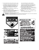
SECTION 1: IMPORTANT SAFE OPERATION PRACTICES WARNING: This symbol points out important safety instructions which, if not followed, could endanger the personal safety and/or property of yourself and others. Read and follow all instructions in this manual before attempting to operate this machine. Failure to comply with these instructions may result in personal injury. When you see this symbol—heed its warning.
. Follow the manufacturer’s recommendations for wheel weights or counterweights to improve stability. 5. Use extra care with grass catchers or other attachments. These can change the stability of the machine. 6. Keep all movement on the slopes slow and gradual. Do not make sudden changes in speed or direction. Rapid engagement or braking could cause the front of the machine to lift and rapidly flip over backwards which could cause serious injury. 7. Avoid starting or stopping on a slope.
e. Extinguish all cigarettes, cigars, pipes and other sources of ignition. f. Never fuel machine indoors. g. Never remove gas cap or add fuel while the engine is hot or running. Allow engine to cool at least two minutes before refueling. h. Never over fill fuel tank. Fill tank to no more than ½ inch below bottom of filler neck to allow space for fuel expansion. i. Replace gasoline cap and tighten securely. j. If gasoline is spilled, wipe it off the engine and equipment. Move unit to another area.
replace immediately with original equipment manufacturer’s (O.E.M.) parts only, listed in this manual. “Use of parts which do not meet the original equipment specifications may lead to improper performance and compromise safety!” 12. Do not change the engine governor settings or overspeed the engine. The governor controls the maximum safe operating speed of the engine. 13. Maintain or replace safety and instruction labels, as necessary. 14. Observe proper disposal laws and regulations for gas, oil, etc.
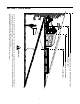
SECTION 2: SLOPE GAUGE FO LD O ND OTT ED L I NE 15° P TING A 15 °S LO P E OR A FENCE POST A CORNER OF A BUILDING A POWER POLE SIGHT AND HOLD THIS LEVEL WITH A VERTICAL TREE , RE RE S EN WARNING Do not mow on inclines with a slope in excess of 15 degrees (a rise of approximately 2-1/2 feet every 10 feet). A riding mower could overturn and cause serious injury.
SECTION 3: TRACTOR SET-UP Gas and Oil Fill-up Front/Bottom of Hood The gasoline tank is located under the fender and has a capacity of three gallons. Unthread the fuel cap by turning it counterclockwise. Use only clean, fresh (under 30 days old), unleaded gasoline. Fill tank to no more than four inches below the top of the filler neck to allow space for fuel expansion. Do not overfill. Pull Upward WARNING: Use extreme care when handling gasoline.
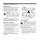
SECTION 4: KNOW YOUR LAWN TRACTOR A B H C + BATTERY PTO / BLADE ENGAGE OIL PRESSURE HOURS 1/10 I PARKING P BRAKE D J K E L M F G N NOTE: Steering Wheel not shown for clarity.
Throttle Control Lever The throttle control lever is located on the left side of the tractor’s dash panel. This lever controls the speed of the engine. When set in a given position, the throttle will maintain a uniform engine speed. Ignition Switch Module Fast Position WARNING: Never leave a running machine unattended. Always disengage PTO, move shift lever into neutral position, set parking brake, stop engine and remove key to prevent unintended starting.
Hour Meter Power Take-Off (PTO) Control Switch Located in the center of the tractor’s console, the hour meter operates whenever the ignition key is rotated out of the STOP position and records the actual hours of tractor operation. See Figure 4. 23.5 BATTERY To engage the power to the cutting deck or other (separately available) attachments, pull the knob of the PTO switch outward. Push the PTO switch knob inward to disengage the power to the cutting deck.
SECTION 5: OPERATING YOUR LAWN TRACTOR WARNING: Use extreme caution while operating the tractor in the REVERSE CAUTION MODE. Always look down and behind before and while backing. Do not operate the tractor when children or others are around. Stop the tractor immediately if someone enters the area. WARNING AVOID SERIOUS INJURY OR DEATH • • • • • • • • • • • • GO UP AND DOWN SLOPES, NOT ACROSS. AVOID SUDDEN TURNS. DO NOT OPERATE THE UNIT WHERE IT COULD SLIP OR TIP.
Setting the Gauge Wheels g. Install one of the front gauge wheels and shoulder screw into the hole in the front bracket that positions the wheel approximately 1/2" above the pavement. h. Note the index hole used and install the other front gauge wheel into the corresponding index hole of the other gauge wheel bracket. • If the gauge wheels and rollers have excessive clearance with the surface below, reset the to the proper ground clearance following the instructions above.
Engaging the Parking Brake • To engage the parking brake: • Fully depress the brake pedal and hold it there while gently pushing the parking brake lever downward. • Hold the parking brake lever down while removing your foot from the brake pedal. • Once engaged, the parking brake lever and the brake pedal will lock in the “down” position. To disengage the parking brake: • IMPORTANT: Do NOT attempt to change the direction of travel when the tractor is in motion.
• Lightly depress the drive pedal. To change the direction of travel to reverse when operating with cruise control, depress the brake pedal to disengage the cruise control and bring the tractor to a complete stop. Then slowly depress the rear portion of the drive pedal with the ball of your foot to travel in reverse. IMPORTANT: Never attempt to move the tractor manually without first opening the hydrostatic relief valve. Doing so will result in serious damage to the tractor’s transmission.
• • • • For best results it is recommended that the first two laps be cut with the discharge thrown towards the center. After the first two laps, reverse the direction to throw the discharge to the outside for the balance of cutting. This will give a better appearance to the lawn. Do not cut the grass too short. Short grass invites weed growth and yellows quickly in dry weather. Mowing should always be done with the engine at full throttle.
• . • • Carefully remove the cotter pin from the castle nut on the right side of the brake assembly. Using a feeler gauge, check the gap between the brake disc and the brake puck of the brake yoke. Proper gap is .011". Tighten the castle nut until the proper gap is achieved. Insert a replacement cotter pin (part # 714-0111) into the castle nut.
• Seat Adjustment Behind the axle, measure the distance horizontally from the inside of the left rim to the inside of the right rim. Note the distance. • The measurement taken in front of the axle should be between 1/16" and 5/16" less than the measurement taken behind the axle. • Adjust if necessary. WARNING: Before operating this machine, make sure the seat is engaged in the seat stop, stand behind the machine and pull back on seat until fully engaged into stop.
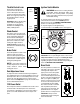
IMPORTANT: The oil fill cap/dipstick must be installed securely onto the tube at all times when the engine is operating. Severe engine damage could result from failure to do so. Changing the Engine OIl FULL The engine oil and oil filter should be changed after the first 24 hours of operation, and after every 100 hours of operation thereafter. Operating Range WARNING: If the engine has been recently run, the engine, muffler and surrounding metal surfaces will be hot and can cause burns to the skin.
• After the oil has finished draining, push the oil drain valve back in, rotate it clockwise to lock the valve closed and re-cap the end of the oil drain valve to keep debris from entering the drain port. • • IMPORTANT: Always change the oil filter when • performing an oil change on your tractor’s engine. Changing the Oil Filter IMPORTANT: The oil fill cap/dipstick must be installed After draining the oil, proceed as follows: securely onto the tube at all times when the engine is operating.
• • NOTE: Do not clean the spark plug in a machine Reinstall the precleaner over the paper element. Reinstall the air cleaner cover and tighten the knob securely. using abrasive grit. Some grit could remain in the spark plug and enter the engine causing extensive wear and damage. Service Paper Element The paper element should be replaced at least every 100 hours of operation. Replace more frequently if the tractor is operated under extremely dusty conditions.
Lubrication IMPORTANT: Make certain the tractor’s discharge chute is directed AWAY from your house, garage, parked cars, etc. WARNING: Before lubricating, repairing, or inspecting, always disengage PTO, set parking brake, stop engine and remove key to prevent unintended starting. 2. Disengage the PTO (Blade Engage), set the parking brake, and stop the engine. 3. Thread the nozzle adapter (packaged with Operator’s Manual) onto the end of your garden hose. 4.
SECTION 8: SERVICE Tires • WARNING: Never exceed the maximum inflation pressure shown on the sidewall of the tire. The recommended operating tire pressure is approximately 10 psi for the rear tires and 14 psi for the front tires. When removing the blades, use a 1-1/8 inch wrench to hold the hex head of the spindle bolt when loosening the hex nut securing the blade. A block of wood may be placed between the deck housing and the cutting edge of the blade to aid in removal of the hex nut securing the blade.
Battery Cutting Deck Removal The battery is sealed and is maintenance-free. Acid levels cannot be checked and fluid can not be added. To remove the cutting deck, proceed as follows: • Place the PTO control switch knob in the disengaged (OFF) position and engage the parking brake. • Place the deck front gauge wheels and rear rollers in their highest setting (lowest deck setting). • Lower the deck by moving the deck lift lever into the bottom notch on the right fender.
Hydrostatic Transmission • Keep the area around the transmission cooling fan free of grass and debris at all times. The hydrostatic transmission is sealed at the factory and is maintenance free. The fluid level cannot be checked and cannot be changed. Insert a 3/8”-drive ratchet wrench (set to loosen) into the square hole found in the idler bracket on the left side of the deck’s surface. See Figure 23.
SECTION 9: OFF-SEASON STORAGE Clean and lubricate the tractor as instructed in Section 7: MAINTAINING YOUR LAWN TRACTOR on page 18 of this manual before storing for an extended period. To empty the system, run the engine until the tank and system are empty. WARNING: Drain fuel only into an approved container outdoors, away from an open flame. Allow engine to cool. Extinguish cigarettes, cigars, pipes, and other sources of ignition prior to draining fuel.
SECTION 11: TROUBLESHOOTING Trouble Possible Cause(s) Corrective Action Engine fails to start PTO/Blade Engage knob engaged. Parking brake not engaged. Spark plug wire(s) disconnected. Throttle control lever not in correct starting position. Choke not activated Fuel tank empty, or stale fuel. Blocked fuel line. Faulty spark plug. Engine flooded. Unit running with CHOKE activated. Spark plug wire(s) loose. Blocked fuel line or stale fuel. Place knob in disengaged (OFF) position. Engage parking brake.
SECTION 12: ATTACHMENTS & ACCESSORIES The following attachments and accessories are compatible to the GT1554 tractor. See your Cub Cadet dealer or the retailer from which you purchased your tractor for information regarding price and availability. NOTE: Cub Cadet GT1554 tractors are NOT designed for use with any type of ground-engaging attachments (e.g. tiller or mulboard plow). Use of this type of equipment WILL void the tractor’s warranty.
SECTION 13: SPECIFICATIONS GT 1554 Capacities Fuel Tank 4.0 gallons (13.2 liters) Engine Crankcase (w/ filter) 2.1 qts. (2.0 liters) Transmission 122 oz. (3.62 liters) Hydrostatic Transmission Make and Model Hydro-Gear 320-3000 Forward Speed 0 m.p.h. - 5.2 m.p.h. Reverse Speed 0 m.p.h. - 2.3 m.p.h. Engine (Air-cooled, 4-cycle) Make Kohler Command Model CV740 Cylinders Twin Bore 3.27 in. (83 mm ) Stroke 2.64 in. (67 mm) Displacement 44.2 cubic in.
KOHLER CO. FEDERAL AND CALIFORNIA EMISSION CONTROL SYSTEMS LIMITED WARRANTY UTILITY AND LAWN AND GARDEN ENGINES The U.S. Environmental Protection Agency (EPA), the California Air Resources Board (CARB), and Kohler Co. are pleased to explain the Federal and California Emission Control Systems Warranty on your small off-road equipment engine. For California, engines produced in 1995 and later must be designed, built and equipped to meet the state’s stringent anti-smog standards.
CUB CADET LLC MANUFACTURER’S ONE YEAR LIMITED WARRANTY (COMMERCIAL USE) The limited warranty set forth below is given by CUB CADET LLC (“CUB CADET”) with respect to new merchandise purchased and used in the United States, its possessions and territories.
CUB CADET LLC MANUFACTURER’S LIMITED WARRANTY (RESIDENTIAL USE) The limited warranty set forth below is given by CUB CADET LLC (“CUB CADET”) with respect to new merchandise purchased and used in the United States, its possessions and territories.