
Operator`s manual

9se c t i O n 3 — as s e M b l y & se t -up
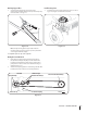
Attaching Support Tubes
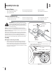
1. Secure the left support tube to the front of the
undercarriage assembly with the clevis pin and hairpin clip
removed earlier. See Fig. 3-11.
Note: To help in lining up the support tube with the
mounting hole it may be necessary to push up and down
on the auger lift handle slightly.
2. Repeat the previous step on the right side.
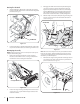
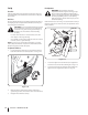
Routing the Lower Drive Belt
1. Route the lower drive belt around the lower pulley on
the spindle assembly, both pulleys on the double-idler
bracket found beneath the undercarriage, and the drive
pulley found on the rear of the snow thrower housing as
illustrated in Fig. 3-13.
2. Attach tension spring (found on undercarriage double-idler
bracket) to the hex screw if it is not already attached.
Figure 3-11
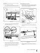
Install Steering Covers
1. Install the two new steering mechanism covers as seen in
Fig. 3-12 using the 3 screws removed earlier.
Figure 3-13
Spindle Pulley
Snow Thrower Drive Pulley
Undercarriage
Double-Idler Pulleys
Left Side
Figure 3-12
View from top
Front
Tension Spring