
Operator`s manual

8 se c t i O n 3— as s e M b l y & se t -up
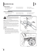
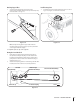
Attaching The Lift Handle
1. Attach lift handle to lift bracket on the right side of auger
housing assembly with two hex screws and two flange nuts
provided. See Fig. 3-7.
2. Fasten the lift cable to the lift handle with two of the cable
ties provided. Pull the cable ties until snug and trim excess
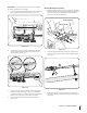
Mounting Auger Assembly
NOTE: It will be necessary to have a second person assist you to
complete the following steps.
1. Remove the steering mechanism cover by removing
the three screws which secure it. See Fig. 3-8. Retain the
hardware for later use during this installation.
2. Position the auger housing assembly in front of the tractor
as seen in Fig. 3-8. Lay the belt and support tubes on the
installation surface.
3. Disengage the brake and release the hydrostatic bypass
rods (see your tractor’s owner’s manual for location of
bypass rods) and carefully move the tractor forward (by
pushing, NOT driving it) so that support tubes found on
the rear of the auger housing assembly are positioned
between the tractor’s front tires. Set the parking brake.
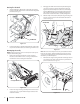
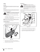
4. With the help of an assistant, lift up the auger housing and
move it so that it rests over the shoulder bolts found on
tractor See Fig. 3-9.
Note: On some units it may be necessary to install the shoulder
bolts onto the tractor. Simply install the bolts as shown in Fig.
3-9 and secure with a flange lock nut. Both hardware parts are
included in your hardware pack.
5. Maneuver the auger housing until the mounting holes line
up. Insert the two quick release pins from your hardware
pack on both sides. See Fig. 3-10.
Shoulder Bolt
Figure 3-9
Steering Mechanism Cover
Figure 3-8
Quick Release Pin
Figure 3-10
Lift Handle
Lift Bracket
Figure 3-7