
Operator`s manual

7se c t i O n 3 — as s e M b l y & se t -up
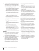
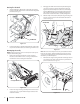
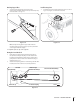
Attaching Chute Directional Control
Attach the chute directional control assembly to the upper 1.
lift link on the left side of the auger housing. Assemble with
two hex screws and two saddle washers as illustrated in
Fig. 3-5. Secure with two flange nuts.
Secure the upper chute crank rod (A) to the joint block on 2.
the lower chute crank rod with the cotter pin (B) provided.
See Fig. 3-6.
3. Fasten chute tilt cables to chute directional control with
two of the cable ties provided. Pull cable ties until snug and
trim excess.
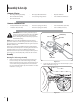
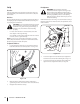
IMPORTANT: Use a second person to assist you or a hydraulic
floor lift to complete steps 3 through 6.
Place the undercarriage assembly beneath the tractor and 3.
lift it up against the frame of the tractor. See Fig. 3-3.
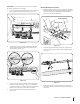
The weld pins on the top of the undercarriage assembly 4.
should go through the aligning holes found along the
tractor’s frame. See Fig. 3-4.
Fasten the undercarriage assembly to the frame with the 5.
hairpin clips removed in step 1. See Fig. 3-4. The hairpin
clips will be inserted on the top in the front holes and in the
bottom on the rear holes as seen in the inset below.
Route the upper drive belt around the engine pulley. 6.
See Fig. 3-4.
Figure 3-3
Upper Lift Link
Chute Directional
Control Assembly
Figure 3-5
A
B
Figure 3-6
Figure 3-4