
Operator`s manual

Assembly & Set-Up
3
6
WARNING! Before installing attachment, place
tractor on a firm and level surface. Place the PTO in
the disengaged (OFF) position, set the parking
brake, shut engine off and remove key to prevent
unintended starting.
NOTE: References to LEFT and RIGHT indicate the left and
right sides of the tractor when facing forward in the operator’s
position. Reference to the FRONT indicates the grille end; to the
REAR the drawbar end.
Your tractor’s cutting deck, PTO belt and front deck stabilizer
bracket must be removed prior to mounting the snow thrower
attachment. Refer to your tractor’s Operator’s Manual for
detailed instructions. If your tractor is equipped with any front-
end accessory (i.e. front bumper kit), it must also be removed.
Assembly
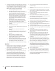
Mounting The Undercarriage Assembly
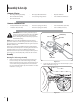
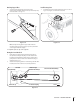
Remove and retain the four hairpin clips from the pins 1.
found on the top side of the undercarriage assembly.
Remove and retain the two rear pins and hex nuts found
on the undercarriage assembly. Remove and retain the
two clevis pins with hairpin clips. This hardware is for later
installation. See Fig. 3–1.
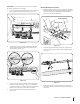
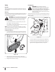
Fasten the two pins and hex nuts, removed in step 1, to the 2.
frame of the rider. See Fig. 3-2
Figure 3-1
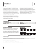
Contents of Carton
One Auger Housing Assembly• One Upper Chute Crank Rod• Operator’s Manual•
One Lift Handle Assembly• Two steering Linkage Covers• Two Self-adhesive Reflectors•
One Hardware Pack•
Clevis Pin
Pin
Hex Nut
HairPin Clip
Figure 3-2
Contents of Hardware Pack
Two Quick Release Pins (714-04061)• Extension Spring (732-04237)• Two Shoulder Bolts (738-0143)•
Five Cable Ties (725-0157)• Extension Spring (932-0594A)• Two Lock Nuts (912-3000)•