
Manual

G730 26
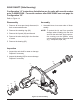
CHARGE PUMP
RefertoFigures17,18
Disassembly
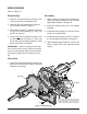
1. Mark the orientation of the charge pump
cover relative to the main housing, prior to
removal. Refer to gure 17.
2. Remove the hex head screws (134), charge
pump cover, gerotor assembly, and the O-
ring (132). Remove the connecting tubes
(130) at this point – onlyifthecentersection
willberemoved. A pick type tool can be used
to remove the connection tubes.
Inspection
1. Inspect the gerotor assembly for
wear or damage.
Replace if necessary.
Assembly
1. Reassemble all parts in the reverse
order of disassembly.
NOTE: When reinstalling the charge pump
components,replacetheO-ring(132)
Also replace the connecting tubes
(130),iftheyhavebeenremoved.
2. Align the mark on the charge pump cover,
from step 1, Disassembly, with the mark on
the main housing.
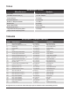
3. When tightening the fasteners, refer to the
table on page 20 for the required torque
values.
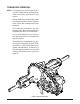
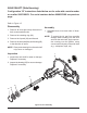
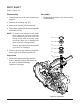
Figure 18, Charge Pump
NOTE: Asageneralrule,usethelowendof
the torque specication on fasteners
whenreassemblingtheunit.
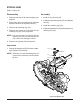
Figure 17, Charge Pump Cover Orientation
130
132
134
Charge Pump Cover
Main Housing
Mark
131
133