
Manual

18 G730
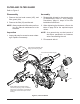
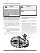
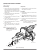
Figure 10, Brake Setting
RefertoFigures9and10
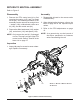
BRAKE SETTING
1. Remove the brake arm bias spring (185),
the cotter pin (182) and loosen the brake
castle nut (181). Refer to gure 8.
2. Insert a 0.015” feeler gage between the
brake rotor (171) and top brake puck, and
then set the brake by nger tightening or
loosening the castle nut.
3. Install a new cotter pin to secure the castle
nut, and then install the brake arm bias
spring.
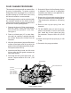
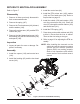
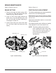
RefertoFigure11
FRICTION PACK ADJUSTMENT
The friction pack dampens or holds the operator
control lever in its desired position.
Adjustment for the amount of drag or holding
force can be made by turning the friction pack
nut in or out.
Adjustments should be made in no more than
1/4 turn increments.
Over-tightening will result in difculty or inability
of the operator to move the control lever.
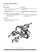
NOTE: Thefactorysettingforthefriction
packistighteningofthefrictionpack
nutto100in-lbs(11Nm)torque.The
frictionpacknutisthenbackedoff
perthevehiclemanufacturer’s
specications.
Figure 11, Friction Pack Adjustment
Brake Rotor (171)
BRAKE MAINTENANCE
Cotter Pin (182)
Castle Nut (181)
Brake Arm (179)
Friction Pack Nut
Control Arm