
Manual

G730 17
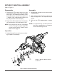
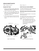
BRAKE ARM & BRAKE ASSEMBLY
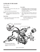
Figure 9, Brake Assembly
RefertoFigure9
Disassembly
1. Remove the cotter pin (182) and discard.
Mark the orientation of the bias spring (185),
and long screw (176). Remove the bias
spring (185), the castle nut (181), and the
washer (184).
2. Remove the brake arm (179), and the brake
compression spring (178).
3. Remove the bolt (175), the bolt (176), and
the spacer (183).
4. Remove the brake yoke (174), the puck
plate (172), and the brake puck (170).
5. Remove the two brake pins (177) from the
brake yoke (174).
6. Remove the brake rotor (171), the inner
puck (170) and the seal (10) — discard the
seal.
NOTE: Onlyremovetheseal(10)if
damagedorworn,orifdoinga
completedisassembly.
Referto“SealKit”intheItems
Listonpage37.
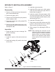
Inspection
1. Inspect all parts for excessive wear or dam-
age. Replace if necessary.
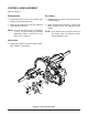
Assembly
1. Reassemble all parts in the reverse order
of disassembly.
2. When tightening the fasteners, refer to the
table on page 20 for the required torque
values.
3. Install new cotter pin (182) and lip seal (10)
from seal kit.
NOTE: Asageneralrule,usethelowendof
the torque specication on fasteners
whenreassemblingtheunit.
170
172
182
Side Housing (2)
185
175
177
174
184
181
178
176
183
171
173
170
10
179