
Manual

16 G730
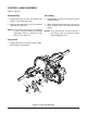
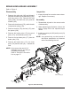
CONTROL ARM ASSEMBLY
Refer to Figure 8
Disassembly
1. Remove the lock nut (47), the washer (45)
and the Torx head screw (46).
2. Remove the control arm (44), the washers
(48) and the stud (42).
NOTE: Onlyremovetheseal(41)ifdamaged
orworn.Thesealcannotbeserviced
separately. Refer to “Seal Kit” in the
ItemsListonpage37.
Inspection
1. Inspect all parts for excessive wear or dam-
age. Replace if necessary.
Assembly
1. Reassemble all parts in the reverse order
of disassembly.
2. When tightening the fasteners, refer to the
table on page 20 for the required torque
values.
NOTE: Asageneralrule,usethelowendof
the torque spec on fasteners when
reassemblingtheunit.
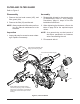
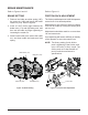
Figure 8, Control Arm Assembly
41
42
48
45
47
44
46