G730® Integrated Hydrostatic Transaxle Service and Repair Manual BLN-52864 October, 2011
Table Of Contents Foreword...................................................... 1 Tools............................................................. 20 Description and Operation............................ 2 Torques......................................................... 20 Hydraulic Schematic..................................... 3 Transaxle Removal....................................... 21 External Features......................................... 4 Side Housing ..................................
FOREWORD Headquartered in Sullivan, Illinois, Hydro-Gear ® is a world leader in the design, manufacture, and service of quality hydrostatic transaxles for the lawn and garden industry. The mission of our company is to be recognized by our customers and the industry as a world-class supplier and the quality leader in everything we do. This Service and Repair Manual is designed to provide information useful in servicing and troubleshooting the Hydro-Gear G730® Integrated Hydrostatic Transaxle.
DESCRIPTION AND OPERATION Introduction The purpose of this manual is to provide information useful in servicing the Hydro-Gear ® G730 ® Integrated Hydrostatic Transaxle. This manual includes the G730’s general descriptions, hydraulic schematics, technical specifications, servicing and troubleshooting procedures. Other than recommended oil changes, the transaxle normally will not require servicing during the life of the vehicle in which it is installed.
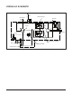
HYDRAULIC SCHEMATIC Vent Input Shaft Case Reservoir Bypass Pump Motor Motor Shaft Filter System Check Valves Charge Relief Charge Pump Figure 1, Hydraulic Schematic With Charge Pump G730 3
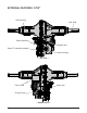
EXTERNAL FEATURES G730® Side Housing Axle Shaft Brake Assembly Bypass Arm Return To Neutral Assembly Main Housing — Top View — Filter Guard Brake Arm Charge Pump — Bottom View — 4 G730
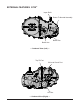
EXTERNAL FEATURES G730® Input Shaft Return To Neutral Assembly Brake Arm Brake Disc — Outboard View (Left) — Top Fill Port Oil Level Check Port Oil Filter — Outboard View (Right) — G730 5
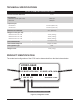
TECHNICAL SPECIFICATIONS G730 ® TECHNICAL SPECIFICATIONS Overall Transaxle Reduction 27.5:1 Input Speeds Maximum Hi-Idle (No Load) 3600 rpm Minimum 1800 rpm Output Torque Intermittent 445 lb-ft (603 N-m) Continuous 230 lb-ft (312 N-m) Maximum Tire Diameter 23 in (584 mm) Weight on Tires (per unit) Maximum with 20” tires 770 lb (350 kg) Maximum with 22” tires 700 lb (318 kg) Maximum with 23” tires 665 lb (302 kg) Axle Shaft Diameter 1.00 in (25.
SAFETY This symbol points out important safety instructions which, if not followed, could endanger the personal safety and/or property of yourself and others. Read and follow all instructions in this manual before attempting maintenance on your transaxle. When you see this symbol - HEED ITS WARNING. Wear appropriate clothing. Loose or hanging clothing or jewelry can be hazardous. Use the appropriate safety equipment, such as eye and hearing protection, and safety-toe and slip-proof shoes.
TROUBLESHOOTING WARNING Do not attempt any servicing or adjustments with the engine running. Use extreme caution while inspecting the drive belt assembly and all vehicle linkage! Follow all safety procedures outlined in the vehicle owner’s manual. In many cases, problems with the G730™ are not related to a defective transaxle, but are caused by slipping drive belts, partially engaged bypass valves, and loose or damaged control linkages.
SERVICE AND MAINTENANCE External Maintenance Regular external maintenance of the G730® should include the following: 1. Check the vehicle operator’s manual for the recommended load ratings. Insure that the current application does not exceed load rating. 2. Check oil level in accordance with “Fluid Change Procedure,” step 9. Refer to page 11. 3. Inspect the vehicle drive belt, idler pulley(s), and idler spring(s). Insure that no belt slippage can occur. Slippage can cause low input speed to the transaxle.
FILTER AND FILTER GUARD Refer to Figure 3 Disassembly Assembly 1. Remove the hex head screws (105), and filter guard (106). 2. Remove the filter (23) and discard. 1. Reassemble all parts in the reverse order of disassembly. Refer to “Fluid Change Procedures,” page 11, steps 3-5 for filter installation instructions. NOTE: Always replace the filter when preforming any internal maintenance to the transaxle. 2. When tightening the fasteners, refer to the table on page 20 for the required torque values.
FLUID CHANGE PROCEDURE This transaxle is designed with an external filter for ease of maintenance. To ensure constant fluid quality levels and longer life, an initial oil and filter change at 75-100 hours, then every 400 hours thereafter is recommended. The following procedure can be performed with the transaxle installed in the vehicle, and the vehicle on level ground. Apply the bypass valve and lock the vehicle parking brake. 1. Remove the three 1/4” filter guard screws and filter guard.
PURGING PROCEDURES Due to the effects air has on efficiency in hydrostatic drive applications, it is critical that it is purged from the system. Air creates inefficiency because its compression and expansion rate is higher than that of the oil approved for use in hydrostatic drive systems. The following procedures are best performed with the vehicle drive wheels off the ground. Then repeated under normal operating conditions.
RETURN TO NEUTRAL SETTING WARNING WARNING POTENTIAL FOR SERIOUS INJURY Do not attempt any servicing or adjustments with the engine running. Use extreme caution while inspecting the drive belt assembly and all vehicle linkage! Inattention to proper safety, operation, or maintenance procedures could result in personal injury, or damage to the equipment. Before servicing or repairing the G730® transaxle, fully read and understand the safety precautions described in this section.
RETURN TO NEUTRAL ASSEMBLY Refer to Figure 6 Disassembly Assembly 1. Remove the RTN control arm kit by first removing the spring (147) and Torx head screw (46). The remaining members of the assembly can be removed as a single item – washer (146), unidirectional scissor arm kit (145), and the control arm (44). 1. Reassemble all parts in the reverse order of disassembly. 2. Remove the Allen head screw (142), washer (45), neutral arm (141) and spacer (140).
RETURN TO NEUTRAL/ROS ASSEMBLY Refer to Figure 7 3. Install the control arm (44). Disassembly 4. Install the RTN scissor arm (145), washer (146) and Torx head screw (46). Refer to torque chart on page 15. 1. Remove all items previously discussed in their recommended order. 2. Remove the spring (147). 3. Remove the Torx head screw (46), discard, and the washer (146). 4. Remove the scissor arm (145), and the RTN control arm (44). 5.
CONTROL ARM ASSEMBLY Refer to Figure 8 Disassembly Assembly 1. Remove the lock nut (47), the washer (45) and the Torx head screw (46). 1. Reassemble all parts in the reverse order of disassembly. 2. Remove the control arm (44), the washers (48) and the stud (42). 2. When tightening the fasteners, refer to the table on page 20 for the required torque values. NOTE: Only remove the seal (41) if damaged or worn. The seal cannot be serviced separately. Refer to “Seal Kit” in the Items List on page 37.
BRAKE ARM & BRAKE ASSEMBLY Refer to Figure 9 Disassembly Inspection 1. Remove the cotter pin (182) and discard. Mark the orientation of the bias spring (185), and long screw (176). Remove the bias spring (185), the castle nut (181), and the washer (184). 1. Inspect all parts for excessive wear or damage. Replace if necessary. Assembly 1. Reassemble all parts in the reverse order of disassembly. 2. Remove the brake arm (179), and the brake compression spring (178). 3.
BRAKE MAINTENANCE Refer to Figures 9 and 10 Refer to Figure 11 BRAKE SETTING FRICTION PACK ADJUSTMENT 1. Remove the brake arm bias spring (185), the cotter pin (182) and loosen the brake castle nut (181). Refer to figure 8. The friction pack dampens or holds the operator control lever in its desired position. 2. Insert a 0.015” feeler gage between the brake rotor (171) and top brake puck, and then set the brake by finger tightening or loosening the castle nut. 3.
TEAR DOWN AND REASSEMBLY How to Use This Manual Each subassembly illustrated in this manual is illustrated with an exploded view showing the parts involved. The item reference numbers in each illustration are for assembly instructions only. See page 37 for part names and descriptions. A complete exploded view and item list of the transaxle is provided at the end of the repair section. General Instructions Cleanliness is a primary means of assuring satisfactory life on repaired units.
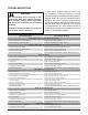
TOOLS Miscellaneous R E QUIRED TOOL S Hub Puller Flat Blade Screw Driver (2) Torque Wrench Air Impact Wrench Rubber or Neoprene Mallet Breaker Bar Side Cutters/Snips Needle Nose Pliers Large External Snap Ring Pliers Large Internal Snap Ring Pliers Sockets Small Internal Snap Ring Pliers 1/2”-3/8” Adapter 3/8” Deep 1-1/8” Deep 1/4” Allen 3/4” Deep 9/16” Deep T-40 Torx Head 7/8” Deep TORQUES Item Description R E Q U I R ED TORQUE VAL UES Torque Operation 4 Plug 9/16-18 (Metal) 110 -150 lb-in Oil
TRANSAXLE REMOVAL NOTE: It is necessary to remove the G730™ from the vehicle before performing the repair procedures presented in this section. Before starting any disassembly, make certain that your work area is neat and clean. Clean the external parts of the transaxle. The following procedures are presented in the order recommended for a complete tear down of the transaxle. Do not disassemble the unit any farther than necessary to accomplish the required repairs.
SIDE HOUSING Refer to Figure 13 Disassembly Assembly 1. Remove all external items previously discussed in their recommended order. 1. Apply a bead of sealant around the perimeter of the main housing face. See “Sealant Application Diagram” on page 34. 2. Remove filter (23) and discard. Drain oil from transaxle. Refer to page 11. 3. Remove the screws (7), separate side housing (2) from main housing (1), using “pry points” as required. 4.
AXLE SHAFT (Side Housing) Configuration “A” instructions listed below are for units with a serial number prior to 9068YXXXX. For serial numbers after 9068YXXXX see next page for Configuration “B”. Refer to Figure 14 Disassembly Assembly 1. Remove all items previously discussed, in their recommended order. 1. Assemble items in reverse order of disassembly. 2. Remove the retaining ring (90).
AXLE SHAFT (Side Housing) Configuration “B” instructions listed below are for units with a serial number on or after 9068YXXXX. For serial numbers before 9068YXXXX see previous page. Refer to Figure 15 Disassembly Assembly 1. Remove all items previously discussed, in their recommended order. 1. Assemble items in reverse order of disassembly. 2. Remove the retaining ring (90).
BULL, PINION AND REDUCTION GEARS Refer to Figure 16 Disassembly Assembly 1. Remove all external items previously discussed in their recommended order. 1. Install the spacer (92) and bevel gear (152) onto the axle shaft (94) in the main housing. 2. Remove washer (80) and reduction gear set (81-82) as an assembly and set aside. Remove second washer (80) and jack shaft pin (83). 3. Install the bull gear (91), two miter gears (153) with two differential pins (154) onto the axle (94). 3.
CHARGE PUMP Refer to Figures 17, 18 Disassembly 1. Mark the orientation of the charge pump cover relative to the main housing, prior to removal. Refer to figure 17. NOTE: As a general rule, use the low end of the torque specification on fasteners when reassembling the unit. 2. Remove the hex head screws (134), charge pump cover, gerotor assembly, and the Oring (132). Remove the connecting tubes (130) at this point – only if the center section will be removed.
INPUT SHAFT Refer to Figure 19 Disassembly Assembly 1. Requires removal of all items beginning on page 22. 1. Reassemble all parts in the reverse order of disassembly. 2. Remove the retaining ring (57). 3. Remove the lip seal (56) and discard. 4. Remove the washer (55) and the pump shaft assembly (52–53). NOTE: To assist in the removal of the pump shaft, lightly tap (using a neoprene head hammer) the shaft from the charge pump side of housing.
BYPASS ARM Refer to Figure 20 Disassembly Assembly 1. Requires removal of all items beginning on page 22. 1. Install a new lip seal (30). 2. Remove the push-on retaining ring (35) and discard. Remove the bypass arm (34). 3. Remove the retaining ring (33). 4. Remove the bypass rod (32) and the clip retaining ring (31) as a single item. 2. Install the clip retaining ring (31) and bypass rod (32). 3. Install the retaining ring (33). 4. Install the bypass arm (34) and new push-on retaining ring (35).
SWASHPLATE Refer to Figures 21, 22 Disassembly Assembly 1. Requires removal of all items beginning on page 22. 1. Reassemble all parts in the reverse order of disassembly. 2. Remove the swashplate (40) and pump cylinder block assembly (69) as a single item. 2. Apply a light coating of oil to running surfaces on center section, swashplate bearing races, thrust bearing assembly and pump block assembly. 3.
CENTER SECTION Refer to Figure 23 Disassembly Assembly 1. Requires removal of all items beginning on page 22. 1. Reassemble all parts in the reverse order of disassembly. 2. Remove the center section mounting screws (27). 2. Apply a light coating of oil to all running surfaces on the center section. 3. Remove the center section, the motor shaft (73) and the motor cylinder block assembly (64) as a single item. 3. Place the thrust bearing assembly (60) into the main housing (1). 4.
CENTER SECTION (Continued) 60 Thick Race Towards Pistons 64 27 73 74 1 27 70 71 Center Section (20) 72 Figure 23, Center Section 31 G730
CENTER SECTION KIT Refer to Figure 24 Disassembly Assembly 1. Remove the bypass plate (22) from the center section. 1. Install the charge relief kit (202). Beginning with the ball, then the spring, followed by, the cross pin. 2. Remove the plug seals (26) and discard. Refer to figure 24, on page 32. IMPORTANT: Before removing the check plugs, it is important to note their specific location, i.e.
CHECK PLUGS & SEALS CYLINDER BLOCKS Refer to Figure 25 Refer to Figure 26 In order to gain access to the check plugs (24 & 25), it is necessary to remove the plug seals (26). This is accomplished by inserting a seal hook or puller into, and through, one of the insertion points (rectangular recesses) on the plug seal, refer to figure 24. After successfully removing the plug seals, discard and replace with new seals. Inspect each component of the cylinder block assemblies for wear or damage.
AXLE SHAFT (Main Housing) Configuration “A” instructions listed below are for units with a serial number prior to 9068YXXXX. For serial numbers after 9068YXXXX see next page for Configuration “B”. Refer to Figure 27 Disassembly Assembly 1. Remove all items previously discussed, in their recommended order. 1. Assemble items in reverse order of disassembly. 2. Remove the retaining ring (90).
AXLE SHAFT (Main Housing) Configuration “B” instructions listed below are for units with a serial number on or after 9068YXXXX. For serial numbers before 9068YXXXX see previous page. Refer to Figure 28 Disassembly Assembly 1. Remove all items previously discussed, in their recommended order. 1. Assemble items in reverse order of disassembly. 2. Remove the retaining ring (90).
ASSEMBLY AFTER A COMPLETE TEAR DOWN If the unit has been torn down completely, the following summary identifies the assembly procedures necessary to completely assemble the unit. Each assembly procedure is located by a page reference. The part reference numbers provided in each assembly procedure are keyed to the individual exploded views, and are also keyed to the complete unit exploded view on page 38-39. 8. Apply sealant to the main housing and center section prior to installing the side cover.
SIDE HOUSING – SCREW TIGHTENING SEQUENCE Starting with the number “1” screw location, tighten sequentially through to “17.” Torque each screw to 105 – 155 lb-in (11.87 – 17.52 Nm). NOTE: As a general rule, use the low end of the torque specification.
G730® TRANSAXLE EXPLODED VIEW Axle Configuration A (See page’s 23, 34) 38 G730
G730® TRANSAXLE EXPLODED VIEW Axle Configuration B (See Page’s 24,35) G730 39
G730® TRANSAXLE PARTS LIST 1 2 4 7 10 20 22 23 24 25 26 27 30 31 32 33 34 35 40 41 44 45 46 52 53 54 55 56 57 60 64 65 69 70 71 72 73 74 80 81 82 83 90 91 92 94 95 96 105 106 115 116 117 118 119 40 Housing, Main Housing, Side Plug 9/16-18 (metal) HFHCS 1/4-20 x 1.25” Seal, Lip .625 x 1.0 Center Section Plate, bypass Filter, Oil Check Plug or Shock Valve Check Plug or Shock Valve Seal, Plug 1.250 x .250 HFHCS 3/8-16 x 1.5 (Patch) Seal, Lip .375 x .75 x .25 Ring, Retaining .
GLOSSARY OF TERMS Axial Piston: Type of design for hydraulic motors and pumps in which the pistons are arranged parallel with the spindle (input or output shaft). Bypass Valve: A valve whose primary function is to open a path for the fluid to bypass the motor or pump. Also referred to occasionally as the freewheel valve or dump valve. Case Drain Line (Return Line): A line returning fluid from the component housing to the reservoir.
Integrated Zero-Turn Transaxle: The combination of a hydrostatic transmission and gear case in one housing to form a complete transaxle. Manifold: A conductor which provides multiple connection ports. Neutral: Typically described as a condition in which fluid flow and system pressure is below that which is required to turn the output shaft of the motor. Pressure Decay: A falling pressure.
NOTES 43 G730
NOTES G730 44
© 2011 HYDRO-GEAR Printed in U.S.A. Rev.