Revision 1 April 2001 1-1
1-2
TABLE OF CONTENTS INTRODUCTION ............................................SECTION 1 COMPONENT DISCRIPTIONS ......................SECTION 2 Battery Pack...................................................................... 2-1 Battery charger.................................................................. 2-2 Electric Drive Motor........................................................... 2-3 Motor Controller ................................................................ 2-3 Instrument Cluster..........
TROUBLESHOOTING ....................................SECTION 6 Fault Indication Table........................................................ 6-2 Motor Will Not Operate...................................................... 6-4 Nothing Works .................................................................. 6-5 Will Not Operate In All Modes ........................................... 6-6 Horn Does Not Work ......................................................... 6-7 Battery Charger Does Not Operate .........
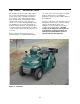
SECTION 1: INTRODUCTION etc., some of the service procedures used with them are similar to those used with the FunRunner. Other procedures will be unique to the FunRunner. The FunRunner is an all-electric utility vehicle. The energy for the FunRunner’s propulsion as well as the operation of its lights, instruments, horn, and etc., come from its 48-volt battery pack. Being electric, the FunRunner emits no exhaust and is therefore a zero emissions vehicle. It is an environmentally friendly vehicle.
1-2
SECTION 2: COMPONENT DESCRIPTION Battery Pack temperature for rating a battery is 78°F. At temperatures above 78°F, the capacity will be higher than the rated capacity. The capacity will be lower than rated capacity when temperatures are below 78°F. At 32°F only about 70 percent of the rated capacity is available. This is significant, because if the FunRunner is operated when the temperature is around 32°F, the range will be reduced by 30 percent.
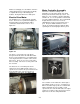
Figure 2-3: Figure 2-2: The charger receives its power from a 110 VAC outlet when a cord is plugged into the charger input connector located in the front of the rear body panel below the seat. The AC power is converted to DC and conditioned to the proper voltage and current output levels to charge the battery. It will take the charger about 7-8 hours to restore a battery pack from fully discharged to fully charged.
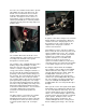
without overcharging. It is desirable to leave the charger plugged in for long periods periodically to equalize the charge of the battery pack modules. Doing this will increase battery life. Motor Controller Assembly The motor controller assembly on the FunRunner is located just ahead of the trunk basket panel under the rear body section. See Figure 2-7. The controller is rated at 150 amps and 48 volts. It is a four-quadrant controller that uses pulse width modulation.
Of course, the controller must be able to provide fully variable speed in each drive mode. The throttle sensor is attached to the accelerator pedal assembly and wired as an input to the controller. See Figure 2-9. The sensor is a potentiometer (a type of variable resistor often called a pot) that will give a continually variable signal from the fully released to fully depressed pedal positions. Figure 2-10: A signal is sent from the charger to the controller during charging of the FunRunner.
will output a signal to the speedometer based on an input from the speed sensor. All of the controller inputs and outputs are shown in Figure 2-11. The diagram shows how the controller is the master of the electrical systems on the FunRunner. Figure 2-11 The center gauge is a speedometer with odometer. The temperature gauge is on the left and it displays the temperature of the controller heat sink. The battery gauge is on the right side and it displays the state of charge of the battery pack.
2-6
SECTION 3: ELECTRICAL AND CHEMICAL SAFETY The FunRunner is equipped with a master disconnect switch. See Figure 3-1. Electrical safety is foremost on the FunRunner, since voltage levels present can cause severe burns, shock, or death. High voltage electric shock can cause muscle contractions. A current of only 10mA can cause muscles to contract. Hands that are exposed to enough electrical current clinch tight and cannot release their grip. Even a small amount of current can cause body tissue damage.
Figure 3-3: FunRunner High Voltage Wiring Practicing safety around high voltage (HV) will protect you and those around you. Keep in mind the following HV safety precautions: • • • • • • • • • • • • • • • • • Have ample light in the work area. Do not work in wet or damp areas. Use proper tools, equipment, and protective devices. Remove all jewelry and metallic items. Keep your tools and equipment in good condition.
• • eyes. The neutralizing agent for sulfuric acid is bicarbonate soda. One pound of soda dissolved in one gallon of water makes a good neutralizing solution that can be used in a spray bottle or poured on a spill. hands until you are sure they have been removed from the electrical current. If the victim has stopped breathing or his/her heart is not pumping, use CPR until help arrives. Only a trained person should administer CPR. If the victim must be moved, take precautions in doing so.
3-4
SECTION 4: REMOVAL & INSTALLATION Canopy................................................................ 4-3 Utility Bed ............................................................ 4-7 Motor/Speed Sensor ........................................... 4-9 Motor Contactor ................................................ 4-15 Controller .......................................................... 4-19 Battery Modules ................................................ 4-23 Battery Charger ............................
Figure 4-1 Figure 4-1A Figure 4-2 Figure 4-3 4-2
SECTION 4: CANOPY INSTALLATION & REMOVAL PARTS REQUIRED TOOLS REQUIRED 710-0642 Hex Washer Screw 1/4-20 x .75 (8) 736-0342 Flat Washer .283 ID x .75 OD (12) 731-2337 Canopy Panel 749-1265 Rear Canopy Frame 749-1266 Front Canopy Frame 710-0136 Hex Cap Screw 1/4-20 x 1.75 (2) 710-1122 Hex Cap Screw 1/4-20 x 2.5 (2) 750-1298 Spacer .280 ID x 437 OD x .250 Lg (2) 750-1299 Spacer .280 ID x 437 OD x .850 Lg (2) Phillips head screwdriver - #2 STEP DETAILS Get tools and check parts. See list above.
4-4
Remove canopy assembly. Remove 4 Hex cap screws from supports and set canopy assembly aside. Remove spacers and store screws. If canopy assembly is not to be replaced, place cap plugs in rear body section and install original Allen screws and spacers in front body panel Remove molded canopy. Remove 8 Phillips head, ¼” x ¾” screws from canopy. Note: If canopy is to be re-installed, this step is not necessary. Lift canopy from supports and set aside. Store screws for replacing canopy.
Figure 4-5 Figure 4-4 Figure 4-6 4-6
UTILITY BED INSTALLATION TOOLS REQUIRED PARTS REQUIRED 607-0013 Utility Box Assembly 710-1832 Machine Screw 1/4-20 x 2” (4) 736-0173 Flat Washer .28 ID x .74 OD (4) #2 Phillips screwdriver 1/16” Allen wrench STEP DETAILS Remove rear trunk lid and trunk basket (Figure 4-4). Raise cover so hinge rod is visible. Loosen 1/16” Allen set screw on each hinge rod locking collar. Slide hinge rod toward one side to remove rod, spacers and trunk lid. Be careful not to loose spacers. Remove trunk basket.
Figure 4-7 Figure 4-8 Figure 4-9 Figure 4-10 4-8
MOTOR/SPEED SENSOR REMOVAL & INSTALLATION TOOLS REQUIRED Wrenches - 3/8”, 1/2”, 9/16”, and 5/8” - socket and box end preferred Pliers Lift or jack - suitable for raising rear of vehicle and being clear when axle/wheel assembly is slid out to the side. Phillips screwdriver - #2 Allen wrench – 3/16” STEP DETAILS Make vehicle safe and accessible. Make sure switch is off and key removed. WARNING: IF MASTER POWER SWITCH IS NOT OFF BATTERY IS STILL CONNECTED TO CONTROLLER.
Figure 4-11 Figure 4-12 Figure 4-13 Figure 4-14 Figure 4-15 4-10
Warning: After axle assembly is completely loosened, motor can fall and catch a hand unless care is used. Suggest a block be placed under differential bracket before axle is completely loosened. Disconnect motor support bracket (Figure 4-11). Bolted to motor and frame on left side of vehicle. 2 bolts, ¼” x ½” - need 3/8” wrench. Remove axle mounting brackets (Figure 4-12). Slide axle assembly from under vehicle (Figure 4-13). Need ½” box end and ½” ratchet wrenches.
Figure 4-16 Figure 4-17 4-12
Install new motor on axle assembly. Place motor on support so differential can be rotated and lined up with motor. Mate motor to differential with speed sensor pointing away from axle. Make sure speed sensor cog and coupler are in place. Replace motor mounting screws using 3/16” Allen wrench. Tighten securely. Mount axle assembly on vehicle. Slide assembly under rear of vehicle and locate close to proper position.
Mounting Screws Figure 4-18 From From Controller To Motor Figure 4-19 From From Controller Controller Activation Wire Terminals Figure 4-20 Figure 4-21 Figure 4-22 4-14
MOTOR CONTACTOR REMOVAL & INSTALLATION STEP DETAILS Make sure vehicle is safe. Switch off and key removed. Parking brake set. Remove canopy assembly (if installed). Remove utility bed (if installed). Remove 4 Phillips head screws. Lift bed off and set aside. Turn off master power switch. Located behind seat. Remove rear body section (Figure 4-18). 4 screws at front below seat. Two screws each side beside seat. Two screws below rear of seat (over battery). 4 screws around top of storage compartment.
4-16
Test operation. Turn on master power switch (behind seat). Make sure vehicle will operate properly. Install parts removed. Install rear body section, utility bed and canopy assembly.
Figure 4-23 Figure 4-24 Figure 4-25 4-18
CONTROLLER REMOVAL & INSTALLATION TOOLS REQUIRED Note: It is easier and safer to remove rear body section and disconnect batteries before removing/replacing controller ½” Socket wrench 9/16” wrench 5/8” wrench # 2 Phillips screwdriver STEP DETAILS Check vehicle safe status. Make sure switch is off and key removed. Warning: Charged capacitors are present in controller. As soon as switch is turned off press horn switch until one capacitor discharges (horn will whine and fade out).
Figure 4-26 Figure 4-27 Figure 4-28 Figure 4-29 Figure 4-31 Figure 4-30 4-20
Disconnect motor and battery power cables (Figure 4-26). Note: it is a smart move to lay a cover over the motor before removing cables. A loose washer inside the motor is no fun. Warning: Insure master switch is off. Place voltmeter across battery terminals on controller and bleed charge off the second capacitor installed in controller until voltage is below 5v. Two top cables are motor power output and two bottom cables are from the battery. Disconnect motor and battery power cables.
Figure 4-32 Figure 4-33 Figure 4-34 4-22
BATTERIES REMOVAL & INSTALLATION STEP DETAILS Make sure parts on hand. Batteries (total of 4 in vehicle) Deka - “Dominator” Model 8G24 - 12v Get required tools. #2 Phillips screwdriver 5/8” wrench 9/16” wrench 1/2” ratchet wrench Insulated pliers 3/16” Allen wrench Make vehicle safe. Switch off and key removed. Remove canopy assembly. Parking brake set. If installed. Remove utility bed. If installed. 4 Phillips screws.
Figure 4-36 Figure 4-35 Figure 4-38 Figure 4-37 Figure 4-39 4-24
Disconnect batteries (Figure 4-35). Warning: Batteries are probably charged and “hot”. Use care to not short cables to frame or other battery terminals. Remove hold down bars. Remove batteries (Figure 4-36). Check fuse. Disconnect cables going from battery to battery first. Loosen wing nuts and slide connectors off. Disconnect cables from battery to controller last. Two bars, one over front 3 batteries and one over rear battery. Be careful not to short bars across batteries.
4-26
Install rear body section. Lift body section and work into position so screw holes are lined up. Replace electrical tie wraps if necessary to hold cables. 4 screws at front below seat. Two screws each side beside seat. Two screws below rear of seat (over battery). 4 screws around top of storage compartment (leave out if utility bed to be mounted). Turn on master power switch. Located behind seat. Operate vehicle. Make sure all parts are operating properly. Install utility bed.
Figure 4-40 Figure 4-41 Figure 4-42 Figure 4-43 4-28
BATTERY CHARGER REMOVAL & INSTALLATION STEP DETAILS Get required tools. #2 Phillips screwdriver ½” wrenches (2) Tool for cutting tie wraps Check machine safe. Remove canopy assembly and utility bed or storage container. Turn off master power switch. Remove rear body section (Figure 4-40). Note: charger cable runs from receptacle on front of rear body section to charger mounted on rear of vehicle frame. Switch off and key removed. Set parking brake. If installed. Located behind seat.
4-30
Turn on master power switch. Located behind seat. Test charger. Make sure it is actually sending current to battery (voltage rises and charge status light comes on when plugged in). 4 Phillips head screws. Replace rear bumper. Connect tail light cables inside storage compartment. Replace rear body section. Connect charger cable to receptacle inside front of body section. Lift body section into place and install screws. Replace storage container or utility bed and canopy assembly.
Figure 4-44 Figure 4-45 Figure 4-46 Figure 4-47 4-32
LIGHTS REMOVAL & INSTALLATION STEP DETAILS Make vehicle safe. Switch off and key removed. Parking brake set. Replace turn signal bulb (Figure 4-44). Twist turn signal receptacle about ¼ turn counterclockwise and remove from fixture. Unplug bulb and replace. Insert receptacle into fixture and turn clockwise ¼ turn into detent. Replace tail/brake light bulb (Figure 4-45). Press locking tab down from inside slot and rotate receptacle about ¼ turn to remove from fixture. Unplug bulb and replace.
Figure 4-48 Figure 4-49 4-34
HEADLIGHT, HORN, HAZARD LIGHT SWITCHES REMOVAL & INSTALLATION STEP DETAILS Check vehicle safe. Switch off and key removed. Set parking brake. Remove switch from panel (Figure 4-48). Reach behind panel and press switch assembly out to the front of the panel (driver’s side). Disconnect switch (Figure 4-49). From wiring harness. Release catches and unplug switch. Replace switch. Plug in new switch and press assembly back into panel. Test operation. Check switch operating properly.
Figure 4-50 Figure 4-51 4-36
IGNITION SWITCH REMOVAL & INSTALLATION STEP DETAILS Make sure vehicle safe. Switch off and key removed. Set parking brake. Turn master power switch off (behind seat). Warning: Voltage is applied to the switch unless the master power switch is off. Be careful. Remove switch (Figure 5-50). Remove hex nut from switch at front of panel. Pull switch out from rear of panel. Unplug switch from jumper harness. Install new switch (Figure 4-51). Plug into wiring harness.
Figure 4-52 Figure 4-53 4-38
TURN SIGNAL SWITCH REMOVAL & INSTALLATION STEP DETAILS Make sure vehicle safe. Switch off and key removed. Set parking brake. Remove switch (Figure 4-52). Use screwdriver to gently pry switch out from panel. Unplug switch. Install new switch (Figure 4-53). Plug new switch into wiring harness. Turn switch so it is properly oriented and press into panel. Test. Switch on. Press switch lever up for right turn signal, down for left. Tie wrap any excess wire so it is out of the way.
Figure 4-54 Figure 4-55 4-40
ACCELERATOR POT (THROTTLE SENSOR) REMOVAL & INSTALLATION STEP DETAILS Make sure vehicle is safe. Switch off and key removed. Set parking brake. Remove pot (Figure 4-54). Two screws – need 5/16” socket wrench or common point screwdriver. Disconnect pot (Figure 4-55). From wiring harness. Install new pot. Mount with two screws. Plug into wiring harness. Make sure any excess wire is tie wrapped out of the way. Test new pot. Check vehicle acceleration and speed are normal.
Figure 4-56 Figure 4-57 4-42
INSTRUMENT CLUSTER REMOVAL & INSTALLATION STEP DETAILS Make sure vehicle is safe. Switch off and key removed. Set parking brake. Pry instrument cluster loose from panel (Figure 4-56). Use care to not damage cluster or panel. Unplug instrument cluster (Figure 4-57). From wiring harness. Install new instrument cluster. Plug new cluster into wiring harness. Press new cluster into housing. Check instruments. Make sure all instruments operating properly. Turn switch off and remove key.
Figure 4-59 Figure 4-58 Figure 4-60 Figure 4-61 4-44
PARK BRAKE SWITCH REMOVAL & INSTALLATION STEP DETAILS Check machine safe. Switch off and key removed. Block wheels if necessary. Remove floor mat and guard plate (Figure 4-58). Pry plastic retaining pins loose. Be careful to not tear floor mat. Guard plate lifts off when floor mat removed. Uncouple brake cable connection (Figure 4-59). Remove spring retainer from clevis pin. Pull clevis pin out and push cables and rod to rear to allow switch removal.
Figure 4-62 Figure 4-63 Figure 4-64 Figure 4-65 Figure 4-66 4-46
BRAKE LIGHT SWITCH REMOVAL & INSTALLATION STEP DETAILS Check machine safe. Switch off and key removed. Block wheels if necessary. Remove floor mat and upper guard plate (Figure 4-62). Pry plastic retaining pins loose. Guard plate lifts off when floor mat removed. Uncouple brake cable connection (Figure 4-63). Remove spring retainer from clevis pin. Pull clevis pin out and push cables and rod to rear to allow switch removal. Remove lower guard plate (Figure 4-64).
4-48
Connect brake cables. Install clevis on brake lever. Make sure clevis pin and spring pin are secure. Check lights. Make sure brake light is operating properly. Replace upper guard plate. So pins in floor mat will hold it in place. Replace floor mat. Press pins into holes in floor.
Figure 4-67 Figure 4-68 4-50
HORN REMOVAL & INSTALLATION STEP DETAILS Make sure vehicle safe. Switch off and key out. Parking brake set. Adjust steering. Turn front wheels as far to the right as possible. Horn is accessible through right wheel well. Disconnect horn (Figure 4-67). Remove spade connectors from tabs on horn. Note that green wire is connected to positive and black to negative terminals. Remove horn from bracket (Figure 4-68). Reach between front bumper and horn mounting bracket and unscrew front of horn (by hand).
4-52
SECTION 5: TEST PROCEDURES Ignition Switch & Jumper Harness....................... 5-3 Accelerator Pot (Throttle Sensor) ........................ 5-9 Motor................................................................. 5-11 Motor Contactor ................................................ 5-15 Speed Sensor ................................................... 5-19 Brake Switch ..................................................... 5-21 Park Brake Switch .............................................
SECTION 5: Figure 5-1 Figure 5-2 5-2
IGNITION SWITCH & JUMPER HARNESS TEST PROCEDURES STEP DETAILS Make vehicle safe. Ignition switch off and key removed. Parking brake set. Disconnect jumper harness from main harness. Connect ohmmeter leads to pins 3 and 4 of jumper harness (See Figure 5-1). Readings should be as shown below when ignition switch is in position shown: Reverse………………1 k ohms Off……………………..open circuit Hi………………………. 2 k ohms Lo……………………… 4 k ohms Connect ohmmeter leads to pins 2 and 3 (readings same as pins 3 and 4).
Figure 5-3 5-4
JUMPER HARNESS TESTING PROCEDURES Step Details Jumper harness has resistors in the wiring and must be tested separately from the switch when switch malfunction is suspected. Problem might be in harness and not switch. An ohmmeter is required. Make vehicle safe. Switch off and key removed. Parking brake set. Remove harness section. Unplug from back of switch. Disconnect from main harness. Measure resistances between pins as shown in Figure 5-3.
Figure 5-4 5-6
IGNITION SWITCH TESTING PROCEDURES STEP DETAILS Make vehicle safe. Switch off and key removed. Parking brake set. Remove switch. Remove retainer nut and pull switch out from back of panel. Unplug jumper harness from switch. Check switch continuity. See Figure 5-4. Use ohmmeter to check pins as shown on Figure 5-4. Pins shown should show near zero ohms when switch is in positions shown below. Reverse: B to F D to A Off position: none of the listed pins connected.
Figure 5-5 Figure 5-6 5-8
ACCELERATOR POT (THROTTLE SENSOR) TESTING PROCEDURES STEP DETAILS Make sure vehicle safe. Turn ignition switch off and remove key. Set parking brake. Check resistance of pot. See Figure 5-5. Disconnect pot from harness and take measurements on pot side of connection while depressing accelerator. Pin numbers are on the connector. Pin 1 to pin 3………… 5 k ohms at all times. Pin 1 to pin 2………… 15 k ohms to 10 k ohms. Pin 2 to pin 3………… 10 k ohms to 15 k ohms. Measure continuity. See Figure 5-6.
Figure 5-7 5-10
MOTOR TEST PROCEDURES STEP DETAILS Make vehicle safe. Ignition switch off and key removed. Parking brake set. Remove utility bed (or storage compartment). Whichever is installed. Remove 4 screws from utility bed or lift storage compartment out. Turn off master power switch. Located behind seat. Remove canopy assembly. If installed, refer to Section 4. Remove rear body section. Refer to Section 4. Disconnect one motor cable. Recommend disconnect motor return cable from controller.
Figure 5-8 5-12
Test motor current draw (Figure 5-8). Note: Test should be done with driver only, (no payload) and on level ground. If motor is weak, performance is bad or is suspected to cause low range or overheating of controller. Connect clamp on inductive current sensor to one of the motor cables and set meter to read current of up to 150 amps. Drive vehicle and record current readings at various speeds as follows. Drive at a steady speed on level ground.
Figure 5-9 Figure 5-10 5-14
MOTOR CONTACTOR TEST PROCEDURES STEP DETAILS Make vehicle safe. Ignition switch off and key removed. Parking brake set. Turn off master power switch. Switch behind seat. Remove utility bed (or storage compartment). Whichever is installed. Remove canopy assembly. If installed, refer to Section 4. Remove rear body section. Refer to Section 4. Disconnect large controller (positive motor output) cable from contactor.
5-16
Replace contactor if necessary. If voltage is present at activator terminals but does not cause contactor to close. If contactor closes but more than one ohm of resistance is present between motor power terminals. Reconnect motor power cable. To original position. Turn on master power switch. Located behind seat. Check operation. Make sure vehicle operates properly. Reassemble. Rear body section. Utility bed or storage container. Canopy assembly.
1 Volts 3 blue 2 black brown Sensor Plug 1KΩ _ + Battery Speed Sensor Figure 5-11 5-18
SPEED SENSOR TEST PROCEDURES STEP DETAILS Remove utility bed. If equipped. Remove trunk basket. Lifts out. Test speed sensor using test tool. Jack and support rear of vehicle with tires off floor. Plug tool to the speed sensor. Connect voltmeter to tool. Turn switch to “on.” Note: This test can be done with a DMM, but it is more easily done with an analog voltmeter. Slightly move the tire until voltage reads approximately 9 volts. Slightly move the tire more until the voltage reads near zero.
Figure 5-12 Figure 5-13 5-20
BRAKE SWITCH TEST PROCEDURES STEP DETAILS Remove rubber floor mat. Pry out plastic retaining pins. Remove upper guard plate. Lifts off. Remove brake pull and lower guard plate. See Figure 5-12. Remove spring clip and clevis pin from brake pull. Remove two hex head bolts from lower guard plate. Remove guard plate and remove brake pull or secure out of way. Test switch. See Figure 5-13. With both wires still plugged to switch and key to an “on” position.
Figure 5-14 5-22
PARK BRAKE SWITCH TEST STEP DETAILS Remove rubber floor mat. Pry out plastic retaining pins. Remove upper guard plate. Lifts off. Test Switch. With both wires still plugged to switch and key to an “on” position, check instrument cluster to make sure selected mode and on lights are illuminated (block wheels or raise rear wheels off ground to prevent accidental runaway of vehicle). Touch the voltmeter leads to the spade terminals just in front of the wire connectors (polarity not important).
Figure 5-15 Figure 5-16 5-24
DIRECTIONAL SIGNAL SWITCH TEST STEP DETAILS Remove signal switch. Gently pry switch from dash. Remove signal switch. Set parking brake with switch plugged in and key to an on position. Check instrument cluster to make sure the on light and selected mode light is illuminated. Check voltage at switch from orange to green wires. Should be 6 volts with signal switch off and 0 volts with signal switch in the right turn position. Test switch. See Figure 5-15. Check voltage from white to green wires.
Figure 5-17 Figure 5-18 5-26
INSTRUMENT CLUSTER TEST PROCEDURES (Nothing on cluster works but rest of vehicle ok) STEP DETAILS Remove instrument cluster. Gently and carefully pry cluster from dash. Unplug connector. From back of cluster. Check for power to cluster. Set park brake. Turn ignition switch to an on position. Check voltage from red wire (pin 5) to green wire (pin 12). Should be 12 volts. See Figure 5-17. Note: Pin locations are numbered on back of plug.
5-28
CHARGER TESTING PROCEDURES • It is important for the charger to operate properly to completely charge the batteries, have a full range, provide long battery life, and do it all safely. • • The charger must supply current to the battery pack to recharge it. As the battery pack accepts more current, the voltage of the pack will rise. The voltage cannot go over a set amount without damage to the battery and possible excessive gassing of the battery.
If the charger performed all the steps required, it is operating normally. If the charger does not charge according to this procedure, it may undercharge or overcharge the battery modules resulting in short battery life and loss of range.
BATTERY PACK EVALUATION As batteries age and acquire more cycles on them, they begin to loose capacity. A cycle is one complete charge and discharge event. The battery’s cycle life is the amount of charge/discharge cycles it can take before it no longer meets the minimum capacity requirements. ok. The new modules will not be at the same capacity as the old and the imbalance will worsen with continued cycles. There are several factors that effect the cycle life of a battery.
of each other until the end of charge where they should all become almost equal. If new battery modules were installed, leave charger on overnight. The extended float charge will help balance the pack. charger is operating properly, then the battery pack capacity is most likely low. Note: Batteries that have lost capacity will usually still have the same power they had previously.
SECTION 6: TROUBLESHOOTING Fault Indication Table.......................................... 6-2 Motor Will Not Operate ....................................... 6-4 Nothing Works .................................................... 6-5 Will Not Operate In All Modes ............................. 6-6 Horn Does Not Work........................................... 6-7 Battery Charger Does Not Operate ..................... 6-7 Low Range..........................................................
FAULT INDICATION SYSTEM The controller on the FunRunner is equipped with onboard diagnostic help. The fault, battery, charge, and temperature LED indicators on the instrument cluster as well as an audible beep from the controller are used to indicate various faults. See Figure 6-1. Observing the lights to see if they stay on, flash constantly, or have a repeated number of pulses while listening to the number of audible pulses will alert you to a fault indication.
Fault Indication Table Digits refer to Number of Pulses Fault Keyoff Cutback Low Battery Throttle Sensor Fault Non Neutral Startup Return to Neutral Charge Inhibit Indicator Cause Flt Bat Chg Tmp Audio 1 Malfunction in key switch circuit flash 2@NNT Battery voltage approaching lower limit 2 on Battery low on initial startup on Battery low while driving 3 3 Throttle sensor circuit malfunction on initial startup 4 1 Throttle sensor circuit malfunction while driving 4 4 Throttle depressed during initial s
PROBLEM POSSIBLE CAUSES CORRECTIVE ACTION Motor will not operate (lights and charger ok). Check fault indication. Refer to fault indication table. Battery problem. Check battery voltage at controller connections. If no voltage, check master switch, all battery connections and main fuse. Repair as necessary. Motor fault.
PROBLEM POSSIBLE CAUSES CORRECTIVE ACTION Note: Charge indicator light would normally be on during a charge inhibit but could be malfunctioning. Note: Brake lights would most likely be on without depressing brake pedal if the brake switch was at fault. Test brake switch. Replace if necessary. Brake switch fault. Check voltage at controller motor terminals with key set to high while depressing accelerator. Voltage should rise as accelerator is depressed.
PROBLEM POSSIBLE CAUSES CORRECTIVE ACTION Switch Connector Lock Connector Red wire Pin 1 to Pin 30 Black wire Pin 2 to Pin 31 Faulty controller. White wire Pin 3 to Pin 32 Green wire Pin 4 to Pin 33 If any of these readings show open circuit, repair or replace wiring harness as needed. If ignition switch and jumper harness check good and battery voltage is present at controller, check for controller malfunction. Vehicle operates in one or more but not all modes. Faulty key switch.
PROBLEM POSSIBLE CAUSES CORRECTIVE ACTION readings should be less than 1 ohm. Main Harness Key Large Twist Switch Connector Lock Controller Connector Faulty controller. Red wire Pin 1 to Pin 30 Black wire Pin 2 to Pin 31 White wire Pin 3 to Pin 32 Green wire Pin 4 to Pin 33 If wiring harness has continuity on all four wires, then controller is most likely faulty. Faulty wiring harness. Horn does not work. No voltage to horn. Faulty horn.
PROBLEM POSSIBLE CAUSES CORRECTIVE ACTION switch. Broken wire. If no voltage to horn switch, check continuity of green switch wire to pin 38 on large controller twist lock connector and white wire to pin 40. If open circuit, replace or repair wire. Controller fault. If horn switch has voltage and operates properly but there is no voltage to horn, check continuity of white horn wire to pin 13 of large controller twist lock connector and green wire to pin 14. If open circuit, replace or repair wire.
PROBLEM POSSIBLE CAUSES CORRECTIVE ACTION for a gauge that will not move up from the minimum position. red zone. Note: Pin locations are numbered on back of connector. Faulty wire. If gauge does not move or is not close to given area, replace instrument cluster. If gauge is close to the given area, then check continuity of gauge wire to controller. Unplug instrument cluster connector at controller. Check continuity.
PROBLEM Speedometer will not work (other instrument cluster gauges and lights ok). POSSIBLE CAUSES Faulty controller. Faulty speed sensor. Faulty speedometer. Note: Pin locations are numbered on back of connector. CORRECTIVE ACTION Test sensor. Refer to Section 5. Replace if needed. Raise and support rear of vehicle with wheels off ground. Remove instrument cluster and unplug connector on rear of cluster.
PROBLEM POSSIBLE CAUSES CORRECTIVE ACTION Pin 19 On light Pin 23 High light Pin 24 Faulty wire. Low light Pin 15 Charge light Pin 20 Park light Pin 8 Headlight Pin 7 When jumped, the indicator should illuminate. If no illumination, replace instrument cluster. If illumination, check continuity of wire to controller. Unplug connector from instrument cluster and check continuity to large twist lock connector at controller for the indicator being tested.
PROBLEM POSSIBLE CAUSES CORRECTIVE ACTION Pin 35 High Pin 24 to Pin 34 Low Pin 15 to Pin 42 Charge Pin 20 to Pin 45 Park Pin 8 to Pin 57 Lights Pin 7 to Pin 49 If no continuity, repair or replace wire harness as needed. If continuity ok, replace controller only when you are sure that the signal to trigger or activate the indicator is working properly. Head and tail lights not working. Bad switch. Turn ignition switch to a run position and check voltage on hazard light switch.
PROBLEM POSSIBLE CAUSES CORRECTIVE ACTION controller is at fault. If switch and switch circuit is ok, possibility of all bulbs burned out, broken wire, or bad controller. Remove left headlight bulb and check voltage across wires – should be 12 volts with headlight switch on. 12 volts present – check bulbs. 12 volts not present – check continuity of wires to small controller twist lock connector. Red wire at headlight connector to pin 2. Black wire at headlight connector to pin 4.
PROBLEM POSSIBLE CAUSES CORRECTIVE ACTION No rear lights (front lights ok). Open rear lights return path. Unplug main harness from tail/brake light harness on one side. Check continuity of rear lights return wires. Tail/Brake Light Harness Plug Small Twist Lock Controller Plug Green wires (both) to Pin 5 If no continuity, repair or replace harness as needed. If continuity, controller is at fault unless all rear bulbs are bad. Front lights not working on right or left side only.
PROBLEM POSSIBLE CAUSES CORRECTIVE ACTION If switch and switch circuit is ok – possibility of all bulbs burned out, broken, or bad controller. Remove left front turn signal bulb and check for pulsing 12 volts at bulb socket. Voltage present, check bulbs. No voltage present – check continuity of wires to small controller twist lock connector. Green wire at bulb socket to pin 8. Black wire at bulb socket to pin 4. If no continuity – check wires to other lights and repair as needed. Faulty controller.
PROBLEM POSSIBLE CAUSES CORRECTIVE ACTION No voltage to lights. Unplug connector at light harness front or rear on affected side. Turn ignition switch to on position and turn signal light switch on. Check voltage at harness connector: orange/black to green for left side, orange to green for right side. Should have pulsating 12 volts. on one side or both (other lights ok). If voltage ok, check light harnesses and bulbs. Repair or replace as needed.
CONTROLLER TWIST LOCK CONNECTION PIN IDENTIFICATION Pin 57 pin connector 1 2 4 5 6 7 8 9 10 11 12 13 14 15 16 17 18 19 20 21 22 23 24 25 26 27 28 29 30 31 32 33 34 35 36 37 38 39 40 41 42 43 COLOR Org Wht Wht Grn Blk Red Grn Wht Red Bare Red Blk Wht Org Red Blk Wht Grn Org/blk Org/blk Org/blk Org Grn Wht Wht Org Org/blk Org/blk 44 FUNCTION Pin 57 pin connector 45 46 47 48 49 50 51 52 53 54 55 56 57 n/c n/c n/c n/c n/c n/c n/c n/c n/c Contactor relay (positive) Contactor relay (negative) Auxiliary ho