Safe Operation Practices • Set-Up • Operation • Maintenance • Service • Troubleshooting • Warranty Operator’s Manual Front Tine Tiller — Model FT24 WARNING READ AND FOLLOW ALL SAFETY RULES AND INSTRUCTIONS IN THIS MANUAL BEFORE ATTEMPTING TO OPERATE THIS MACHINE. FAILURE TO COMPLY WITH THESE INSTRUCTIONS MAY RESULT IN PERSONAL INJURY. CUB CADET LLC, P.O. BOX 361131 CLEVELAND, OHIO 44136-0019 Printed In USA Form No.
1 To The Owner Thank You Thank you for purchasing a Garden Tiller manufactured by Cub Cadet LLC. It was carefully engineered to provide excellent performance when properly operated and maintained. Please read this entire manual prior to operating the equipment. It instructs you how to safely and easily set up, operate and maintain your machine. Please be sure that you, and any other persons who will operate the machine, carefully follow the recommended safety practices at all times.
2 Important Safe Operation Practices WARNING! This symbol points out important safety instructions which, if not followed, could endanger the personal safety and/or property of yourself and others. Read and follow all instructions in this manual before attempting to operate this machine. Failure to comply with these instructions may result in personal injury. When you see this symbol.
c. When practical, remove gas-powered equipment from the truck or trailer and refuel it on the ground. If this is not possible, then refuel such equipment on a trailer with a portable container, rather than from a gasoline dispenser nozzle. 11. After striking a foreign object, stop the engine, disconnect the spark plug wire and ground against the engine. Thoroughly inspect the machine for any damage. Repair the damage before starting and operating. d.
9. If the fuel tank has to be drained, do this outdoors. 10. Observe proper disposal laws and regulations for gas, oil, etc. to protect the environment. Notice Regarding Emissions Engines which are certified to comply with California and federal EPA emission regulations for SORE (Small Off Road Equipment) are certified to operate on regular unleaded gasoline, and may include the following emission control systems: Engine Modification (EM) and Three Way Catalyst (TWC) if so equipped.
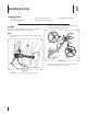
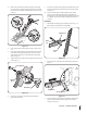
3 Assembly & Set-Up Contents of Carton • One Tiller • One Handlebar Assembly • One Operator’s Manual • One Engine Operator’s Manual Assembly 2. References to the right and left side of tiller are determined from behind the equipment in the operating position. • One Depth Gage Assembly Hook the “Z” end of the forward clutch cable (A) into the forward tine engagement lever Fig. 3–2. Handle 1. Identify the forward clutch cable and reverse clutch cables. Fig. 3–1. B A Figure 3-2 3.
4. Remove the hex bolt and cupped washer from the right side of the frame. Hold the cable guide bracket on the left side of frame as it will fall when the bolt is removed. Step 1 in Fig. 3–3. 9. Insert the carriage bolt through the welded bracket on the handle, bell washer, handle brace and into the hand knob. See Fig. 3–4. 10. Select one of the three handle height positions (three notches in the welded handle bracket) and tighten the hand knob to secure the handle in the desired position. Fig. 3–4.
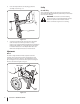
4. Insert the depth stake into the depth gage bracket assembly as seen in Fig. 3–7. Set-Up Gas & Oil Fill-Up Service the Engine with gasoline and oil as instructed in the seperate Engine Operator’s Manual packed with your tiller. Read the instructions carefully. WARNING! Use extreme care when handling gasoline. Gasoline is extremely flammable and the vapors are explosive. Never fuel the machine indoors or while the engine is hot or running. Cotter Pin Clevis Pin Figure 3-7 5.
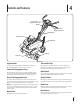
4 Controls and Features Reverse Tine Engagement Lever Handle Forward Tine Engagement Lever Handle Knob Throttle Control Depth Stake End Cap Tiller Tines Engine Controls Figure 4-1 See the separate Engine Operator’s Manual for additional information and functions of the engine controls. Forward Tine Engagement Lever The forward tine control lever is located beneath the upper section of the handle. Squeezing the lever against the handle engages the tine drive. Release the lever to stop the tines.
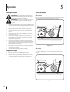
5 Operation Starting the Engine WARNING! Read, understand, and follow all the instructions and warnings posted on the machine and in this manual before operating. Setting the Depth Yoke Forward Place the wheel yoke so that wheels are forward (nearest to tines) for shallow tilling, cultivating and transport. See Fig. 5-1. WARNING! Be sure no one is standing in front of the tiller while the engine is running or being started. 1. Attach the spark plug wire to the spark plug.
Depth Stake Tilling Procedure The depth stake acts as a brake for the tiller and controls the depth and speed at which the machine will operate. Remove the clevis pin and hairpin clip to raise or lower depth stake. See Fig. 5-3. When tilling, leave approximately eight inches of untilled soil between the first and second tilling paths, then make the third path between the first and second, Fig. 5-4.
Cultivating Procedures For cultivating, a two to three inch depth is desirable. The tine width can be reduced to 13 inches by removing the outer tines completely from the tiller. See the Maintenance & Adjustments Section for instructions on removing the tines. When laying out plant rows, be sure to allow enough width to permit cultivation between the rows. In growing corn or similar crops, check-row planting will permit cross cultivation and practically eliminate hand hoeing. See Fig. 5-5.
6 Maintenance & Adjustments WARNING! Disconnect the spark plug wire and ground it against the engine before performing any repairs. Maintenance Adjustments Cable Adjustment From time to time you may need to adjust the tension on the forward and reverse tine engagement cables. See Fig. 6-1. Engine Refer to the seperate Engine Operator’s Manual for engine maintenance instructions. Air Cleaner Service the air cleaner every 10 hours under normal operating conditions.
3. Turn the cable collar section one or two turns to add or lesson tension on the cable. See Fig. 6-3. End Caps The end cap, which is used to avoid tilled soil from overflowing onto unwanted areas, are removable from the axle. Remove the hairpin clip and clevis pin that secure each end cap and slide the end caps off the axle. See Fig. 6-5. Cable Collar Cotter Pin Clevis Pin Figure 6-3 4. End Cap Retighten the lock nut against the cable collar. See Fig. 6-4.
Off-Season Storage If the tiller will not be used for a period longer than 30 days, the following steps should be taken to prepare the tiller for storage. 1. Clean the exterior of the engine and the entire tiller thoroughly. Lubricate the tiller as described in the lubrication instructions. 2. The use of pressure washers is not recommended for cleaning your tiller. They may cause damage to electric components, spindles, pulleys, bearings or the engine.
7 Service Belt Replacement 3. Reverse Drive Belt Your tiller has been engineered with a belt made of special material (Kevlar Tensile) for longer life and better performance. It should not be replaced with an off-the-shelf belt. Order all belts through you authorized service dealer. 1. Disconnect and ground the spark plug wire against the engine. 2. Remove the belt cover from the left side of the tiller by removing the two self-tapping screws and hex stop nut and washer. See Fig. 7–1.
Forward Drive Belt 4. 1. Remove the reverse drive belt as instructed in the previous section. 2. Remove the return spring. See Fig. 7–3. The forward idler belt will not clear the belt keepers near the engine pulley. You must remove the reverse idler bracket to allow the belt to move off of the engine pulley. Remove the two securing screws and move the bracket toward the transmission pulley. Retain the screws for reassembly. See Fig. 7–5. Return Spring Screws Figure 7-3 3.
8 Troubleshooting Problem Engine fails to start Engine runs erratic Engine overheats Tines do not engage 18 Cause Remedy 1. Fuel tank empty, or stale fuel 1. Fill tank with clean, fresh gasoline 2. Throttle control lever not in correct starting position (if equipped) 2. Move throttle lever to start position 3. Blocked fuel line 3. Clean fuel line 4. Dirty air cleaner 4. Refer to the Engine Operator’s Manual 5. Choke not in ON position 5. Move switch to ON position 6.
9 Replacement Parts Component Part Number and Description 742-0530 Tine 714-0149B 711-0415 Cotter Pin Clevis Pin 754-0428 754-0429 Forward V-Belt, Reverse V-Belt 746-0918 749-0953 Forward Cable Reverse Cable 734-1268 Wheels, 8” x 1.75” 98079-56846 Spark Plug (BPRGES) 17211-ZL8-023 Air Filter Phone (800) 965-4CUB to order replacement parts or a complete Parts Manual (have your full model number and serial number ready). Parts Manual downloads are also available free of charge at www.
CUB CADET LLC MANUFACTURER’S LIMITED WARRANTY FOR edgers, string trimmers & tillers The limited warranty set forth below is given by Cub Cadet LLC with respect to new merchandise purchased and used in the United States, its possessions and territories, and by MTD Products Limited with respect to new merchandise purchased and used in Canada and/or its territories and possessions. c.
Medidas importantes de seguridad • Configuración • Funcionamiento • Mantenimiento • Servicio • Solución de problemas • Garantía Manual del operador Cultivadora de Dientes Frontales — Modelo FT 24 ADVERTENCIA LEA Y SIGA TODAS LAS INSTRUCCIONES DE ESTE MANUAL ANTES DE PONER EN FUNCIONAMIENTO ESTA MÁQUINA. SI NO RESPETA ESTAS INSTRUCCIONES PUEDE PROVOCAR LESIONES PERSONALES. CUB CADET LLC, P.O. BOX 361131 CLEVELAND, OHIO 44136-0019 Impreso en Estados Unidos de América Formulario No.
Al propietario 1 Gracias Gracias por comprar una Cultivadora fabricada por Cub Cadet LLC LLC. La misma ha sido diseñada cuidadosamente para brindar excelente rendimiento si se la opera y mantiene correctamente. Por favor lea todo este manual antes de operar el equipo. Le indica cómo configurar, operar y mantener la máquina con seguridad y fácilmente.
2 Medidas importantes de seguridad ¡ADVERTENCIA! La presencia de este símbolo indica que se trata de instrucciones importantes de seguridad que se deben respetar para evitar poner en peligro su seguridad personal y/o material y la de otras personas. Lea y siga todas las instrucciones de este manual antes de poner en funcionamiento esta máquina. Si no respeta estas instrucciones puede provocar lesiones personales. Cuando vea este símbolo.
c. d. e. f. g. h. i. j. k. l. Cuando sea factible, retire el equipo a gasolina del camión o remolque y llénelo en el suelo. Si esto no es posible, llene el equipo en un remolque con un contenedor portátil, en vez de hacerlo con una boquilla dispensadora de gasolina. Mantenga la boquilla de llenado en contacto con el borde del depósito de combustible o con la abertura del recipiente en todo momento, hasta terminar la carga. No utilice un dispositivo de boquilla de apertura/cierre.
9. 10. Si debe vaciar el tanque de combustible, hágalo al aire libre. Respete las normas referentes a la disposición correcta de residuos y las reglamentaciones sobre gasolina, aceite, etc. para proteger el medio ambiente.
3 Montaje y Configuración Contenido de la caja • Una cultivadora • Una unidad de manija • Un Manual del operador • Un Manual del operador del motor Montaje 2. Las referencias al lado derecho o izquierdo de la cultivadora se determinan desde la parte posterior de la unidad en la posición de operación. • Una estaca de profundidad Enganche el extremo "Z" del cable del embrague de marcha adelante (A) en la palanca de enganche de los dientes marcha adelante. Fig. 3-2. Manija 1.
4. Retire el perno hexagonal y la arandela cónica del lado derecho del bastidor. Sostenga la ménsula de la guía del cable del lado izquierdo del bastidor ya que se caerá al quitar el perno. Paso 1 en la Fig. 3-3. 9. Inserte el perno de carro a través del soporte soldado de la manija, la arandela campana, la traba de la manija, y dentro de la perilla de mano. Vea la Fig. 3-4. 10. Fig. 3-4. Vuelva a la manija inferior y ajuste el perno hexagonal con firmeza. Medición de profundidad 1 1.
1. Inserte la estaca de profundidad en el conjunto de la ménsula de medición de profundidad tal como se muestra en la Fig. 3-7. Configuración Carga de gas y aceite Cargue el motor con gasolina y aceite como se indica en el Manual del operador del motor que se entrega con la cultivadora por separado. Lea las instrucciones con atención. ¡ADVERTENCIA! Tenga mucho cuidado al trabajar con gasolina. La gasolina es sumamente inflamable y sus vapores pueden causar explosiones.
4 Controles y Características Palanca de enganche de marcha hacia atrás de los dientes Manija Palanca de enganche de marcha hacia adelante de los dientes Perilla de la palanca Control del regulador Estaca de profundidad Tapa de extremo Dientes de la cultivadora Controles del motor Figura 4-1 Consulte el Manual del operador del motor, por separado, para obtener información adicional y detalles sobre las funciones de los controles del motor.
5 Funcionamiento Encendido del motor ¡ADVERTENCIA! Lea, comprenda y siga todas las instrucciones y advertencias que se encuentran en la máquina y en este manual antes de operarla. ¡ADVERTENCIA! Asegúrese de que nadie se Establecimiento de la profundidad Retén hacia adelante Coloque el retén de las ruedas de manera que las ruedas estén hacia delante (punto más cercano a los dientes) para labranza superficial, cultivo y transporte. Vea la Fig. 5-1.
Estaca de profundidad Procedimiento para realizar la labranza La estaca de profundidad funciona como un freno de la cultivadora y controla la profundidad y la velocidad a la cual funciona la máquina. Retire la chaveta de horquilla y el broche de horquilla para subir o bajar la estaca de profundidad. Vea la Fig. 5-3. Al labrar, deje aproximadamente 8 pulgadas de suelo sin labrar entre el primer y el segundo surco labrado, luego haga el tercer surco entre los dos primeros; Fig. 5-4.
Procedimientos para realizar tareas de labranza Es deseable una profundidad de dos a tres pulgadas para realizar la labranza del terreno. El ancho de labranza se puede reducir a 13 pulgadas extrayendo los dientes exteriores completamente de la cultivadora. Consulte la sección Mantenimiento y ajustes para leer las instrucciones para retirar los dientes. Cuando trace las hileras de plantación, asegúrese de dejar un ancho suficiente para poder cultivar entre las hileras.
6 Mantenimiento y Ajustes ¡ADVERTENCIA! Desconecte el cable de la bujía y póngalo haciendo masa contra el motor antes de realizar cualquier reparación. Mantenimiento Motor Ajustes Ajuste de los cables Periódicamente puede ser necesario ajustar la tensión de los cables de enganche de los dientes marcha adelante y marcha atrás. Vea la Fig. 6-1. Consulte las instrucciones para el mantenimiento del motor en el Manual del propietario/operador del motor que se entrega por separado.
1. Gire la parte del collarín del cable una o dos vueltas para aumentar o aflojar la tensión sobre el cable. Vea la Fig. 6-3. Collarín del cable Tapas de extremo La tapa de extremo, que se usa para evitar que la tierra labrada se desborde sobre áreas donde no es deseada, se extrae del eje. Retire el broche de horquilla y la chaveta de horquilla que sujetan cada tapa de extremo y deslice la tapa hasta sacarla del eje. Vea la Fig. 6-5. Pasador de chaveta Pasador de horquilla Figura 6-3 2.
Almacenamiento fuera de temporada Si la cultivadora no se usa por un período de más de 30 días, se deben realizar los siguientes pasos para preparar la cultivadora para el almacenamiento. 1. Limpie el exterior del motor y la cultivadora en su totalidad a fondo. Lubrique la cultivadora según se describe en las instrucciones de lubricación. 2. No se recomienda el uso de lavadoras de presión para la limpieza de la cultivadora.
7 Servicio Cambio de correa 3. Correa de la transmisión de marcha atrás El diseño de la cultivadora incluye una correa de material especial (Kevlar Tracción) que le proporciona mayor duración y mejor rendimiento. No se la debe cambiar por una correa cualquiera. Pida todas las correas a través de su distribuidor de servicio autorizado. 1. Desconéctelos y haga masa con el cable de la bujía contra el motor. 2.
Correa de transmisión de marcha directa 1. Retire la correa de transmisión de marcha atrás tal como se explica en la sección anterior. 2. Retire el resorte de retorno. Vea la Fig. 7-3. 4. Resorte de retorno La correa de la polea loca de marcha hacia adelante no despejará los guardacorreas cerca de la polea del motor. Debe retirar el soporte de polea loca de marcha atrás para permitir que la correa se deslice hacia afuera de la polea del motor.
8 Solución de Problemas Problema Causa El motor no arranca 1. El tanque de combustible está vacío o el combustible es viejo 2. La palanca de control del regulador no está en la posición de arranque correcta. 3. La línea de combustible está bloqueada 4. El depurador de aire está sucio 5. El cebador no está en la posición CHOKE (cebador). 6. Se ha(n) desconectado el(los) cables de las bujías. 7. La bujía no funciona correctamente. 8. Motor ahogado. 1. Llene el tanque con gasolina limpia y fresca. 1.
Notas 11 19
GARANTÍA LIMITADA DE CUB CADET LLC PARA bordeadora de cÉsped, Contemporizador de Cuerda Y Cultivadora de dientes traseros La siguiente garantía limitada es otorgada por Cub Cadet LLC con respecto a nuevos productos adquiridos y utilizados en Estados Unidos, sus posesiones territorios, y por MTD Products Limited con respecto a nuevos productos adquiridos y utilizados en Canadá y/o sus territorios y posesiones. d.