Safe Operation Practices • Set-up • Operation • Product care • Specifications Operator’s Manual Utility Vehicle M 550/750 Record Product Information Model Number Before setting up and operating your new utility vehicle please locate the model plate and record the information in the provided area to the right. You can locate the model plate by looking on the frame above the left rear tire. See the image below.
SAFE OPERATION PRACTICES WARNING This symbol points out important safety instructions which, if not followed, could endanger the personal safety and/or property of yourself and others. Read and follow all instructions in this manual before attempting to operate this vehicle. Failure to comply with these instructions may result in personal injury. When you see this symbol. HEED ITS WARNING! DANGER This vehicle was built to be operated according to the safe operation practices in this manual.
SAFE OPERATION PRACTICES 24. The doors are designed to assist in keeping the operator and passenger inside the vehicle during operation. Do NOT operate vehicle without doors in place. Dress Properly 25. Improper use of the vehicle or failure to properly maintain it could result in decreased vehicle performance or personal injury. 2. Always wear appropriate eye protection and protective clothing. It is also recommended that you wear a properly fitting D.O.T. approved helmet. 26.
SAFE OPERATION PRACTICES Cargo Box Loading/Operation e. Although the OPS, when used with a properly secured seat belt, provides a crush-protective environment in the event of a tip-over or rollover, never take unnecessary risks. 1. Do not exceed vehicle’s Total Load Capacity rating of 1000 lbs (453.5 kg). This includes operator, passenger, accessories, and cargo. 2. Do not exceed 500 lbs (226.7 kg) load in cargo box. CHILDREN 3. Spread load evenly and secure to prevent movement. 1.
SAFE OPERATION PRACTICES d. Keep the nozzle in contact with the rim of the fuel tank or container opening at all times until fueling is complete. Do not use a nozzle lock-open device. 11. Follow the vehicle maintenance and service schedules to ensure that all mechanical and safety systems are working properly and not worn excessively. Failure to do so can result in accidents, injuries, or death. e. Extinguish all cigarettes, cigars, pipes, and other sources of ignition. 12.
SAFE OPERATION PRACTICES SPARK ARRESTOR The spark arrestor should be maintained in effective working order by the operator. In the State of California the above is required by law (Section 4442 of the California Public Resources Code). Other states may have similar laws. Federal laws apply on federal lands.
SAFE OPERATION PRACTICES Before setting up and operating your new utility vehicle please locate the model plate and record the information in the provided area to the right. You can locate the model plate by looking on the frame above the left rear tire. See the image below. This information will be necessary, should you seek technical support via our web site, Customer Support Department, or with a local authorized service dealer.
SET-UP THANK YOU CONTENTS OF CRATE Thank you for purchasing this product. It was carefully engineered to provide excellent performance when properly operated and maintained. • Utility Vehicle (1) • Operator’s Manual (1) • Tool Kit Please read this entire manual prior to operating. It instructs you how to safely and easily set up, operate and maintain your vehicle. Please be sure that you, and any other persons who will operate the vehicle, carefully follow the recommended safety practices at all times.
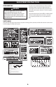
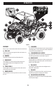
OPERATION (K) K A J D H C I D F B E G Figure 1 FEATURES F. CARGO BED A. FUEL CAP The cargo bed is used to haul materials and is located on the back of the utility vehicle. See the Specifications chart for information on cargo bed capacity and dimensions. B. BUMPER The cargo bed release levers are located on both the RH and LH side of the cargo bed and are used to tilt the cargo bed. Refer to Figure 1 for the location of the features described below.
OPERATION OCCUPANT PROTECTION STRUCTURE (OPS) & SEAT BELTS (NOT SHOWN) WARNING Always wear the seat belt when operating the utility vehicle. This utility vehicle is equipped with an Occupant Protection Structure (OPS) and seat belts. When used together they are effective in reducing crushing injuries to the operator and passenger in the event of an accidental rollover or tip-over. The safety provided by the OPS is minimized if the seat belt is not properly adjusted AND buckled.
OPERATION O. GLOVE BOX D. HORN The horn activates the horn under the hood when depressed. The glove box is a small storage area in the dash on the passenger side of the utility vehicle. E. HAZARD SWITCH P. INSTRUMENT CLUSTER The hazard switch turns the hazards “ON” and “OFF.” The instrument cluster contains: 1 - TACHOMETER 2 - PARKING BRAKE INDICATOR F. TURN SIGNAL SWITCH The turn signal switch controls the turn signals and activates the LH or RH turn signals.
OPERATION NOTE: The engine will not start without the gear shift in the NEUTRAL (N) or PARK (P) position and the brake depressed. • Do not start quickly nor apply the brakes suddenly. • In winter, operate the vehicle after fully warming up the engine. 3. Insert the key into the ignition and turn it to the START position. Release the key when the engine starts (Figure 3). • Do not run the engine at speeds faster than prescribed. • On rough roads, slow down to suitable speeds.
OPERATION Driving the Utility Vehicle 1. Adjust the seat belt to fit comfortably around your lap, then buckle the seat belt. WARNING Do not operate the vehicle without the OPS in place and the seat belt fastened securely around your waist and chest. To activate the 4WD stop the utility vehicle and press down on the upper half of the 2WD/4WD switch. To return to 2WD, stop the utility vehicle and press down on the lower half of the 2WD/4WD switch.
OPERATION Loading the Cargo Bed WARNING WARNING A loaded cargo bed can be very heavy. Do not attempt to dump a heavily loaded cargo bed. The utility vehicle may become unstable if the cargo bed is loaded incorrectly. Avoid loose and unsecured loads or uneven loading of material. 1. Park the vehicle safely on level ground and set parking brake. 2. Empty heavy loads by hand. 1. Verify cargo bed is securely latched before loading. 3.
OPERATION Loading a Utility Vehicle into a Truck or onto a Trailer CHOOSING THE PROPER LOADING RAMP(S) Choosing a reliable ramp and understanding how to properly use it is far and above the best option for safely loading a utility vehicle into your truck or onto your trailer.
OPERATION 3. Face the truck bed or trailer towards a slight incline, which will reduce the steepness of the loading angle by bringing the bottom of the ramps up on the slight incline (Figure 8). 5. Use tie-down straps or cables to secure the ramps to the trailer or truck, via the bumper (steel bumpers only) or trailer hitch safety chain loops. Refer to instructions provided with the ramp. 6. If your utility vehicle is supplied with a roof and/or windshield, remove or fully secure them prior to loading.
PRODUCT CARE MAINTENANCE CHART Follow the Maintenance Schedule given below. This chart describes service guidelines only. Refer to the Engine Operator’s Manual for engine maintenance items listed in the table below.
PRE-START CHECKLIST • Check parking brake. Make sure the parking brake indicator light comes on when the parking brake is ON. • Inspect the instrument panel for broken gauges and warning lamps. • Check the headlights and turn signals. Replace if broken. 18 • Check tire pressure. See Tire Pressure in this section. • Check the joint boots on the drive shaft for damage. If the joint boots are damaged, see an authorized service dealer. * -- Perform more often in dusty conditions.
PRODUCT CARE MAINTENANCE a WARNING To avoid personal injury, be sure to check and service the vehicle on a flat surface with the engine off and the parking brake ON. If servicing under the cargo bed, be sure that the cargo bed is supported so that it can not inadvertently close. Do not touch muffler or exhaust pipes while they are hot; Otherwise, severe burns could result.
PRODUCT CARE Removing the Battery Access Panel Jacking Up the Utility Vehicle Unlock the battery access panel under the seat by rotating the lock knob, then lifting the battery access panel (Figure 13). WARNING To avoid personal injury, death, or vehicle damage do not work under the vehicle unless it is secured by safe stands or suitable blocking. 1. Jack up the front end of the utility vehicle on the front frame tube (a) only (Figure 16 on page 20).
PRODUCT CARE Adjusting the Doors Checking & Adding Oil If required, the doors can be adjusted. To adjust the doors, loosen the two bolts (a) on each hinge, adjust the door as needed. Retighten all four bolts (a) (Figure 18). IMPORTANT! If oil level is low, do not run the engine. 1. Park the vehicle on a flat surface with engine off, remove the seat and engine access panel to access the engine. 2.
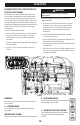
PRODUCT CARE Checking & Adding Engine Coolant 3. Detach the screen and clean the radiator and radiator screen and radiator fins of all debris (Figure 23). CAUTION Do not remove radiator cap while coolant is hot. When cool, slowly rotate to the first stop and allow sufficient time for excess pressure to escape before removing the cap completely. 1. Park the vehicle on a flat surface, remove the hood panel, set the parking brake and shut off the engine. 2.
PRODUCT CARE Checking the Brake Pedal WARNING Stop the engine and chock the wheels before checking brake pedal. If the parking brake is in need of adjustment, proceed as follows: 1. Locate the parking brake adjustment nut near the engine (Figure 26). Inspect the brake pedals for free play (a), pedal stroke (b) and smooth operation (Figure 25). b a a Figure 26 2. Loosen the lock nut (a) and then tighten the bolt (b) to adjust the parking brake.
PRODUCT CARE Checking & Adjusting the Shift Lever Adjusting the Shocks If the shifter and the display image on the instrument cluster do not match or the utility vehicle is not shifting, a shift cable adjustment can be performed. There are three adjustment points on the shocks. The rebound (a), pre-load spring (b) and damping rate (c) can be adjusted. Refer to Figure 29 for the following instructions. 1. Remove the hood and the interior hood panel. 2.
PRODUCT CARE 1. To increase the stiffness of the suspension and increase the absorption of impacts, rotate the compression adjuster screw clockwise towards the “SLOW” (or “0”) position. 2. To decrease the stiffness (soften the ride) rotate the compression adjuster screw counter-clockwise towards the “FAST” (or “18”) position. CAUTION Only use engine oil with API Service Classification of SJ or Higher and JASO-MA Grade. 6. The engine oil capacity is 2.22 quarts (2.1 L).
PRODUCT CARE Replacing Mini Fuses Replacing Rear Brake Cylinder Seal The mini fuses are intended to protect the electrical system. If any of them have blown out, be sure to pinpoint the cause. (See Specifications section, Figure 46 on page 38 for fuse box layout.) See your authorized service dealer to have the rear brake seal changed. Replacing Intake Air Line 1. Disconnect the negative battery cable. See your authorized service dealer to have the air intake line changed. 2.
PRODUCT CARE Antifreeze Burping (Removing Air From) the Coolant System WARNING When using antifreeze, put on some protection such as rubber gloves. (Antifreeze contains poison.) If you should drink antifreeze, throw up at once and seek medical attention. If antifreeze comes in contact with the skin or clothing, wash it off immediately. Do not mix different types of antifreeze. The mixture can produce a chemical reaction between substances.
PRODUCT CARE Cleaning Primary Air Filter Element 4. Remove the inner filter (a) from the paper element (b) (Figure 38). Open the air cleaner cover once a week under ordinary conditions — or daily when used in a dusty place — to get rid of large particles of dust and dirt. NOTE: Do not run the engine with filter element removed. b 1. Remove the air filter access panel. 2. Remove the air filter cover (a) from the three air filter cover holders (b) (Figure 36). a b b Figure 38 a 5.
PRODUCT CARE DRAIN THE AIR INTAKE 1. Remove the nine Allen-head bolts (a) and washers (a) securing the middle skid plate to the bottom of the utility vehicle (Figure 40). a a a a a a a a (a) a 1. Park the vehicle on a flat surface and remove the engine access panel. There is a primary fuel filter on the gas tank and an in-line fuel filter between the gas tank and the engine. 2. If the fuel line and clamps are damaged or deteriorated, replace them. 3.
PRODUCT CARE Battery NOTE: If you store a battery that is not completely charged, the battery may need to be replaced. c WARNING Never remove the battery while the engine is running. Keep electrolyte away from eyes, hands, and clothes. If you are spattered with it, wash it away completely with water immediately and get medical attention. Wear eye protection and rubber gloves when working around the battery. a b NOTE: The factory installed battery is the non-refillable type.
PRODUCT CARE 3. If there is any damage, the assembly must be replaced. 4. Return the spark arrestor (a) to the muffler (b) and reinstall the bolts. MUFFLER 1. Visually check the muffler for cracks or holes in the body, weldment or pipes at regular intervals. 6. With all implements lowered to the ground, coat any exposed rods with grease (if equipped). 7. Remove the battery from the vehicle. Store the battery following the battery storage procedures. 8.
PRODUCT CARE TROUBLESHOOTING WARNING Before performing any type of maintenance/service, disengage all controls and stop the engine. Wait until all moving parts have come to a complete stop. Disconnect spark plug wire and ground it against the engine to prevent unintended starting. Always wear safety glasses during operation or while performing any adjustments or repairs. This section addresses minor service issues.
PRODUCT CARE Problem Engine does not restart when warm Cause Remedy 1. Poor quality fuel 1. Refer to Service manual. Ensure the unit contains at least 1/4 tank of clean fuel. 2. Fuel tank vent plugged 2. Contact your local authorized dealer for service. 3. Dirt in fuel filter 3. Contact your local authorized dealer for service. 4. Damaged electrical harness 4. Contact your local authorized dealer for service. 1. Blown fuse 1. Visually and mechanically inspect all fuses.
PRODUCT CARE Problem Engine overheats Engine loses power Starter does not work Starter cranks slowly Cause Remedy 1. Cooling fan not turning 1. Listen or look for the radiator fan to turn on. The unit must be running, or the key switch in the run position. If the dash indicates the engine has over heated, immediately turn the unit off and then turn the key switch to the run position. If the fan does not turn on, check the fuses.
PRODUCT CARE Problem Battery light comes on when engine is running Vehicle will not move Cause Remedy 1. Weak or Low Battery. 1. Check Battery Voltage. 2. Loose electrical connections within the charging system. 2. Ensure all electrical connections are secure. 3. Excessive current draw from Accessories. 3. Contact your local authorized dealer for a current draw inspection. 1. Shift Lever not in gear. 1. Check the dash display to ensure the desired direction of travel is indicated. 2.
SPECIFICATIONS Make Specifications 1 cylinder, 4-cycle, gasoline, SOHC, liquid cooled Type Displacement cc 546CC for 550UTV 735CC for 750UTV Horsepower Kw (HP) 20.2 (27.1) for 550UTV 28.8 (38.6) for 750UTV Rated Revolution rpm 5500 for 550UTV 6000 for 750UTV Low Idling Revolution rpm 1500 ±150 Fuel Capacity L (U.S. gal.) 28 (7.4) Oil Capacity L (U.S. quart) 2.1 (2.
SPECIFICATIONS Make Suspension Specifications Front Independent, Dual A-arm type Rear Independent, Dual A-arm type Max rolling weight (Towing capacity) kg (lbs.) 544 (1200) Payload capacity (Cargo Bed) kg (lbs.) 227 (500) Vehicle Curb Weight kg (lbs.) 690 (1518) Width mm (in.) 1170 (46.06) Length mm (in.) 900 (35.43) Depth mm (in.) 280 (11) Volume m3 (cu. ft.) 0.29 (10.24) Bed height (Unloaded) mm (in.) 810 (31.89) Cargo bed capacity (1 row/2 row) kg (lbs.
SPECIFICATIONS FUSE BOX K1 K2 F1 K3 F1 20A Fan motor fuse F2 5A Fan control system/Pump relay fuse K5 K4 F2 F3 F4 F5 F6 F7 F8 F9 F10 F11 F12 F13 F14 F3 5A Winch controller fuse F4 5A The four-wheel drive differential control relay fuse OUT Spare Spare fuse fuse Flasher 20A 10A 5A 30A 10A 5A K1:MODEL: HFV11 12-H-R ( DG ) Fuel pump relay K2:MODEL: HFV11 12-H-R ( DG ) Neutral start relay K3:MODEL: HFV11 12-H-R ( DG ) Ignition switch relay K4:MODEL: HFV9 012-1ZR All-wheel-drive rel
Hisun Motors Corp., U.S.A. Emission Control System Warranty Statement YOUR WARRANTY RIGHTS AND OBLIGATIONS The U.S. Environmental Protection Agency and Hisun Motors Corp., U.S.A. (hereinafter “HISUN”) are pleased to explain the emission control system warranty on your Off-Road vehicle. New off-road motor vehicles must be designed, built and equipped to meet U.S. EPA Federal and California anti-smog standards.
Hisun Motors Corp., U.S.A. Limited Warranty on Emission Control System YOUR WARRANTY RIGHTS AND OBLIGATIONS Hisun Motors Corp., U.S.A. warrants that each new off-road vehicle: A. is designed, built and equipped so as to conform at the time of initial retail purchase with all applicable regulations of the United States Environmental Protection Agency, and B.
Hisun Motors Corp., U.S.A. Limited Warranty on Emission Control System B. No express emission control system warranty is given by HISUN except as specifically set forth herein. Any emission control system warranty implied by law, including any warranty of merchantability or fitness for a particular purpose, is limited to the express emission control system warranty terms stated in this warranty. The foregoing statements of warranty are exclusive and in lieu of all other remedies.